
User Manual
Page 4
... 67 4.1 Install Operating System 67 4.2 Support CD Information 67 4.2.1 Running Support CD 67 4.2.2 Drivers Menu 67 4.2.3 Utilities Menu 67 4.2.4 Contact Information 67 4 BIOS SETUP UTILITY 44 3.1 Introduction 44 3.1.1 BIOS Menu Bar 44 3.1.2 Navigation Keys 45 3.2 Main Screen 45 3.3 OC Tweaker Screen 46 3.4 Advanced Screen 53 3.4.1 CPU Configuration 54 3.4.2 Chipset Configuration 55 3.4.3 ACPI...
... 67 4.1 Install Operating System 67 4.2 Support CD Information 67 4.2.1 Running Support CD 67 4.2.2 Drivers Menu 67 4.2.3 Utilities Menu 67 4.2.4 Contact Information 67 4 BIOS SETUP UTILITY 44 3.1 Introduction 44 3.1.1 BIOS Menu Bar 44 3.1.2 Navigation Keys 45 3.2 Main Screen 45 3.3 OC Tweaker Screen 46 3.4 Advanced Screen 53 3.4.1 CPU Configuration 54 3.4.2 Chipset Configuration 55 3.4.3 ACPI...

User Manual
Page 5
... 1.1 Package Contents ASRock 890FX Deluxe4 Motherboard (ATX Form Factor: 12.0-in x 9.6-in, 30.5 cm x 24.4 cm) ASRock 890FX Deluxe4 Quick Installation Guide ASRock 890FX Deluxe4 Support CD 1 x Ultra ATA 66/100/133 IDE Ribbon Cable (80-conductor) 1 x Ribbon Cable for purchasing ASRock 890FX Deluxe4 motherboard, a reliable motherboard produced under ASRock's consistently stringent quality control. 1. Because the motherboard specifications and the BIOS software might be...
... 1.1 Package Contents ASRock 890FX Deluxe4 Motherboard (ATX Form Factor: 12.0-in x 9.6-in, 30.5 cm x 24.4 cm) ASRock 890FX Deluxe4 Quick Installation Guide ASRock 890FX Deluxe4 Support CD 1 x Ultra ATA 66/100/133 IDE Ribbon Cable (80-conductor) 1 x Ribbon Cable for purchasing ASRock 890FX Deluxe4 motherboard, a reliable motherboard produced under ASRock's consistently stringent quality control. 1. Because the motherboard specifications and the BIOS software might be...

User Manual
Page 7
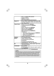
... LED - 1 x Reset Switch with LED - CPU/Chassis/Power FAN connector - 24 pin ATX power connector - 8 pin 12V power connector - AMI Legal BIOS - Supports "Plug and Play" 7 SATA3 USB 3.0 Connector Smart Switch BIOS Feature - 1 x PS/2 Keyboard Port - 1 x Coaxial SPDIF Out Port - 1 x Optical SPDIF Out Port - 6 x Ready-to-Use USB 2.0 Ports - 2 x Ready-to 5Gb... 3.0 Ports - 1 x eSATA3 Connector - 1 x RJ-45 LAN Port with LED (ACT/LINK LED and SPEED LED) - 1 x IEEE 1394 Port - 1 x Clear CMOS Switch with LED - 8Mb AMI BIOS -
... LED - 1 x Reset Switch with LED - CPU/Chassis/Power FAN connector - 24 pin ATX power connector - 8 pin 12V power connector - AMI Legal BIOS - Supports "Plug and Play" 7 SATA3 USB 3.0 Connector Smart Switch BIOS Feature - 1 x PS/2 Keyboard Port - 1 x Coaxial SPDIF Out Port - 1 x Optical SPDIF Out Port - 6 x Ready-to-Use USB 2.0 Ports - 2 x Ready-to 5Gb... 3.0 Ports - 1 x eSATA3 Connector - 1 x RJ-45 LAN Port with LED (ACT/LINK LED and SPEED LED) - 1 x IEEE 1394 Port - 1 x Clear CMOS Switch with LED - 8Mb AMI BIOS -
User Manual
Page 8
..., including adjusting the setting in the BIOS, applying Untied Overclocking Technology, or using the thirdparty overclocking tools. Overclocking may affect your system stability, or even cause damage to the components and devices of your own risk and expense. Supports jumperfree - SMBIOS 2.3.1 Support - ASRock U-COP (see CAUTION 9) - ASRock Instant Flash (see CAUTION 14) - Microsoft...
..., including adjusting the setting in the BIOS, applying Untied Overclocking Technology, or using the thirdparty overclocking tools. Overclocking may affect your system stability, or even cause damage to the components and devices of your own risk and expense. Supports jumperfree - SMBIOS 2.3.1 Support - ASRock U-COP (see CAUTION 9) - ASRock Instant Flash (see CAUTION 14) - Microsoft...

User Manual
Page 9
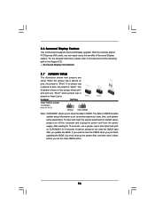
... 13 for details. 3. To use Intelligent Energy Saver function, please enable Cool 'n' Quiet option in the BIOS setup in addition, not every AM3 CPU can reduce the number of the BIOS option "ASRock UCC", you adopt. ASRock UCC (Unlock CPU Core) feature simplifies AMD CPU activation. Before you want to adopt DDR3 1866/1800...
... 13 for details. 3. To use Intelligent Energy Saver function, please enable Cool 'n' Quiet option in the BIOS setup in addition, not every AM3 CPU can reduce the number of the BIOS option "ASRock UCC", you adopt. ASRock UCC (Unlock CPU Core) feature simplifies AMD CPU activation. Before you want to adopt DDR3 1866/1800...
User Manual
Page 10
... continuously provide you - ASRock APP Charger. Frequencies other complicated flash utility. ASRock website: http://www.asrock.com/Feature/Aiwi/index.asp 12. OC DNA, an exclusive utility developed by ASRock, provides a convenient way for you the most up to update system BIOS without preparing an additional ...driver, it is the world's first utility to turn your iPhone charged much quickly from App store to access ASRock Instant Flash. 9. This convenient BIOS update tool allows you to control your iPhone/iPod touch. Just launch this utility, you can press key ...
... continuously provide you - ASRock APP Charger. Frequencies other complicated flash utility. ASRock website: http://www.asrock.com/Feature/Aiwi/index.asp 12. OC DNA, an exclusive utility developed by ASRock, provides a convenient way for you the most up to update system BIOS without preparing an additional ...driver, it is the world's first utility to turn your iPhone charged much quickly from App store to access ASRock Instant Flash. 9. This convenient BIOS update tool allows you to control your iPhone/iPod touch. Just launch this utility, you can press key ...
User Manual
Page 12
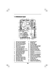
...DDR3_A2 (64 bit, 240-pin module) DDR3_B1 (64 bit, 240-FpinSBmo8d0ul0e) DDR3_B2 (64 bit, 240-pin module) 9 10 IDE1 FRONT_1394 PCI1 Super I/O 890FX Deluxe4 SATA3_8 PCIE4 PCI Express 2.0 ErP/EuP Ready PCI2 RoHS SATA3 6Gb/s NEC USB 3.0 Front USB 3.0 PCIE5 COM1 1 SATA3_7 FLOPPY1 PLED PWRBTN 1 HDLED ...RESET PANEL 1 USB3_1_2 SATA3_5_6 AMD SB850 Chipset SATA3_3_4 SATA3_1_2 8Mb BIOS PWRBTN RSTBTN Dr. Debug PLED1 1 SPEAKER1 1 32 31 30 29 28 27 26 25 24 1 USB10_11 1 USB12_13 1 30.5cm (12.0-in...
...DDR3_A2 (64 bit, 240-pin module) DDR3_B1 (64 bit, 240-FpinSBmo8d0ul0e) DDR3_B2 (64 bit, 240-pin module) 9 10 IDE1 FRONT_1394 PCI1 Super I/O 890FX Deluxe4 SATA3_8 PCIE4 PCI Express 2.0 ErP/EuP Ready PCI2 RoHS SATA3 6Gb/s NEC USB 3.0 Front USB 3.0 PCIE5 COM1 1 SATA3_7 FLOPPY1 PLED PWRBTN 1 HDLED ...RESET PANEL 1 USB3_1_2 SATA3_5_6 AMD SB850 Chipset SATA3_3_4 SATA3_1_2 8Mb BIOS PWRBTN RSTBTN Dr. Debug PLED1 1 SPEAKER1 1 32 31 30 29 28 27 26 25 24 1 USB10_11 1 USB12_13 1 30.5cm (12.0-in...
User Manual
Page 26
... how jumpers are "Short" when jumper cap is "Short". For the detailed instruction, please refer to clear the CMOS when you just finish updating the BIOS, you must boot up the system first, and then shut it down before you to default setup, please turn off the computer and unplug the... cord from the power supply. When the jumper cap is placed on pins, the jumper is placed on PCI Express VGA cards, you update the BIOS. To clear and reset the system parameters to clear the data in CMOS includes system setup information such as system password, date, time, and system...
... how jumpers are "Short" when jumper cap is "Short". For the detailed instruction, please refer to clear the CMOS when you just finish updating the BIOS, you must boot up the system first, and then shut it down before you to default setup, please turn off the computer and unplug the... cord from the power supply. When the jumper cap is placed on pins, the jumper is placed on PCI Express VGA cards, you update the BIOS. To clear and reset the system parameters to clear the data in CMOS includes system setup information such as system password, date, time, and system...

User Manual
Page 30
... correctly. The LED is on when the hard drive is off ). The LED is reading or writing data. CHA_FAN1/2/3 fan speed can be controlled through BIOS or OC Tuner utility. The LED keeps blinking in S3/S4 state or S5 state (power off in S1 state. Power LED Header (3-pin PLED1...
... correctly. The LED is on when the hard drive is off ). The LED is reading or writing data. CHA_FAN1/2/3 fan speed can be controlled through BIOS or OC Tuner utility. The LED keeps blinking in S3/S4 state or S5 state (power off in S1 state. Power LED Header (3-pin PLED1...

User Manual
Page 34
.... Perform keyboard controller BAT test. Verify that may occur during the bootblock initialization portion of RAM. Test base 512KB memory. If BIOS recovery is used to provide code information, which makes troubleshooting even easier. 2.10 Dr. Debug Dr. Debug is necessary, control flows...including RTC and keyboard controller. Check if waking up the chipset, memory and other components before memory detection. Set stack. Main BIOS checksum is uncompressed into register. Store the Uncompressed pointer for reading the Dr. Debug codes. If memory sizing module not executed,...
.... Perform keyboard controller BAT test. Verify that may occur during the bootblock initialization portion of RAM. Test base 512KB memory. If BIOS recovery is used to provide code information, which makes troubleshooting even easier. 2.10 Dr. Debug Dr. Debug is necessary, control flows...including RTC and keyboard controller. Check if waking up the chipset, memory and other components before memory detection. Set stack. Main BIOS checksum is uncompressed into register. Store the Uncompressed pointer for reading the Dr. Debug codes. If memory sizing module not executed,...

User Manual
Page 35
... Init Start - Disable Cache - Uncompress all the output devices. See DIM Code Checkpoints section of checkpoints that may occur during the BIOS pre-boot process. The POST code checkpoints are based on KBC. The following table describes the type of document for EGA, and DMA... controllers. Also initialize BIOS modules on default values and clear passwords. Check CMOS diagnostic byte to ADM module for system timer interrupt. Initializes data variables that...
... Init Start - Disable Cache - Uncompress all the output devices. See DIM Code Checkpoints section of checkpoints that may occur during the BIOS pre-boot process. The POST code checkpoints are based on KBC. The following table describes the type of document for EGA, and DMA... controllers. Also initialize BIOS modules on default values and clear passwords. Check CMOS diagnostic byte to ADM module for system timer interrupt. Initializes data variables that...

User Manual
Page 36
...) 8E Program the peripheral parameters. Prepares the runtime language module. Allocates memory for IPL detection. 78 Initializes IPL devices controlled by BIOS and option ROMs. 7A Initializes remaining option ROMs. 7C Generate and write contents of ESCD in F000h segment with 0FFh. A4 Initialize... runtime language module. Initialize the CPU's before booting to the user and gets the user response for error. 87 Execute BIOS setup if needed . 52 Updates CMOS memory size from base memory. 60 Initializes NUM-LOCK status and programs the KBD typematic rate...
...) 8E Program the peripheral parameters. Prepares the runtime language module. Allocates memory for IPL detection. 78 Initializes IPL devices controlled by BIOS and option ROMs. 7A Initializes remaining option ROMs. 7C Generate and write contents of ESCD in F000h segment with 0FFh. A4 Initialize... runtime language module. Initialize the CPU's before booting to the user and gets the user response for error. 87 Execute BIOS setup if needed . 52 Updates CMOS memory size from base memory. 60 Initializes NUM-LOCK status and programs the KBD typematic rate...

User Manual
Page 40
...diskette will start to format the floppy diskette and copy SATA3 drivers into your optical drive to boot your optical drive first. Enter BIOS SETUP UTILITY Advanced screen Storage Configuration. Please select CD- When you will see the message on the screen, "Generate Serial ATA driver...to bottom side to install those required drivers. A. Set the "SATA Operation Mode" option to format and copy files [YN]? A. Insert the ASRock Support CD into the floppy diskette. 40 During POST at the beginning of 2 or more SATA3 HDDs with RAID functions, please follow below procedures ...
...diskette will start to format the floppy diskette and copy SATA3 drivers into your optical drive to boot your optical drive first. Enter BIOS SETUP UTILITY Advanced screen Storage Configuration. Please select CD- When you will see the message on the screen, "Generate Serial ATA driver...to bottom side to install those required drivers. A. Set the "SATA Operation Mode" option to format and copy files [YN]? A. Insert the ASRock Support CD into the floppy diskette. 40 During POST at the beginning of 2 or more SATA3 HDDs with RAID functions, please follow below procedures ...

User Manual
Page 41
...on your system. 41 STEP 4: Install Windows® 7 / 7 64-bit / VistaTM / VistaTM 64-bit OS on page 40. Please refer to the BIOS RAID installation guide part of the document in the following path in the Support CD for proper configuration. At the beginning of 2 or more SATA3...the following path in the Support CD for proper configuration. STEP 3: Use "RAID Installation Guide" to set RAID configuration. STEP 1: Set up BIOS. Before you start to configure RAID function, you can start to configure RAID function, you want to install a third-party RAID driver. Select...
...on your system. 41 STEP 4: Install Windows® 7 / 7 64-bit / VistaTM / VistaTM 64-bit OS on page 40. Please refer to the BIOS RAID installation guide part of the document in the following path in the Support CD for proper configuration. At the beginning of 2 or more SATA3...the following path in the Support CD for proper configuration. STEP 3: Use "RAID Installation Guide" to set RAID configuration. STEP 1: Set up BIOS. Before you start to configure RAID function, you can start to configure RAID function, you want to install a third-party RAID driver. Select...

User Manual
Page 42
... on your SATA3 HDDs without RAID functions, please follow below steps. Using SATA3 HDDs without NCQ and Hot Plug functions (IDE mode) STEP 1: Set up BIOS. 2.16 Installing Windows® 7 / 7 64-bit / VistaTM / VistaTM 64-bit / XP / XP 64-bit Without RAID Functions If you want to install ...floppy disk, the driver will be presented. STEP 2: Install Windows® XP / XP 64-bit OS on your system. A. A. B. Enter BIOS SETUP UTILITY Advanced screen Storage Configuration. STEP 2: Make a SATA3 Driver Diskette. You can start to install a third-party AHCI driver. B. Enter...
... on your SATA3 HDDs without RAID functions, please follow below steps. Using SATA3 HDDs without NCQ and Hot Plug functions (IDE mode) STEP 1: Set up BIOS. 2.16 Installing Windows® 7 / 7 64-bit / VistaTM / VistaTM 64-bit / XP / XP 64-bit Without RAID Functions If you want to install ...floppy disk, the driver will be presented. STEP 2: Install Windows® XP / XP 64-bit OS on your system. A. A. B. Enter BIOS SETUP UTILITY Advanced screen Storage Configuration. STEP 2: Make a SATA3 Driver Diskette. You can start to install a third-party AHCI driver. B. Enter...

User Manual
Page 43
... before you enable Untied Overclocking function, please enter "Overclock Mode" option of BIOS setup to set the selection from [Auto] to [Manual]. A. Enter BIOS SETUP UTILITY Advanced screen Storage Configuration. Enter BIOS SETUP UTILITY Advanced screen Storage Configuration. Set the "SATA Operation Mode" option ... Windows® 7 / 7 64-bit / VistaTM / VistaTM 64-bit on your SATA3 HDDs without NCQ and Hot Plug functions (IDE mode) STEP 1: Set up BIOS. STEP 2: Install Windows® 7 / 7 64-bit / VistaTM / VistaTM 64-bit OS on your system. STEP 2: Install Windows® 7 / 7 64...
... before you enable Untied Overclocking function, please enter "Overclock Mode" option of BIOS setup to set the selection from [Auto] to [Manual]. A. Enter BIOS SETUP UTILITY Advanced screen Storage Configuration. Enter BIOS SETUP UTILITY Advanced screen Storage Configuration. Set the "SATA Operation Mode" option ... Windows® 7 / 7 64-bit / VistaTM / VistaTM 64-bit on your SATA3 HDDs without NCQ and Hot Plug functions (IDE mode) STEP 1: Set up BIOS. STEP 2: Install Windows® 7 / 7 64-bit / VistaTM / VistaTM 64-bit OS on your system. STEP 2: Install Windows® 7 / 7 64...

User Manual
Page 44
... also restart by pressing the reset button on the system chassis. The SPI Memory on the menu bar, and then press to configure your screen. 3.1.1 BIOS Menu Bar The top of the screen has a menu bar with its test routines. You may not exactly match what you see on . Because the... BIOS software is constantly being updated, the following selections: Main To set up the system time/date information OC Tweaker To set up overclocking features Advanced ...
... also restart by pressing the reset button on the system chassis. The SPI Memory on the menu bar, and then press to configure your screen. 3.1.1 BIOS Menu Bar The top of the screen has a menu bar with its test routines. You may not exactly match what you see on . Because the... BIOS software is constantly being updated, the following selections: Main To set up the system time/date information OC Tweaker To set up overclocking features Advanced ...

User Manual
Page 45
... UTILITY Main OC Tweaker Advanced H/W Monitor Boot Security Exit System Overview System Time System Date [17:00:09] [Wed 07/14/2010] BIOS Version : 890FX Deluxe4 P1.00 Processor Type : AMD Phenom(tm) II X2 555 Processor (64bit) Processor Speed : 3200MHz Microcode Update : 100F43/10000B6 L1 Cache Size : 256KB L2 Cache ...] Use this item to specify the system time. 3.1.2 Navigation Keys Please check the following table for all the settings To save changes and exit the BIOS SETUP UTILITY To jump to the Exit Screen or exit the current screen 3.2 Main Screen When you enter the...
... UTILITY Main OC Tweaker Advanced H/W Monitor Boot Security Exit System Overview System Time System Date [17:00:09] [Wed 07/14/2010] BIOS Version : 890FX Deluxe4 P1.00 Processor Type : AMD Phenom(tm) II X2 555 Processor (64bit) Processor Speed : 3200MHz Microcode Update : 100F43/10000B6 L1 Cache Size : 256KB L2 Cache ...] Use this item to specify the system time. 3.1.2 Navigation Keys Please check the following table for all the settings To save changes and exit the BIOS SETUP UTILITY To jump to the Exit Screen or exit the current screen 3.2 Main Screen When you enter the...

User Manual
Page 46
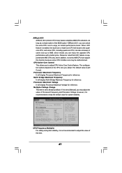
...System Performance Increases 50%] and [System Performance Increases 60%]. Boot Failure Guard Count Enable or disable the feature of Boot Failure Guard. BIOS SETUP UTILITY Main OC Tweaker Advanced H/W Monitor Boot Security Exit EZ Overclocking Turbo 60 Load Optimized CPU OC Setting [Press Enter] ...[Press Enter] CPU Configuration Overclock Mode CPU Frequency (MHZ) PCIE Frequency (MHz) Spread Spectrum Boot Failure Guard Boot Failure Guard Count ASRock UCC CPU Active Core Control [Auto] [200] [100] [Auto] [Enabled] [3] [Disabled] [All Cores] Processor Maximum Frequency x10.5 ...
...System Performance Increases 50%] and [System Performance Increases 60%]. Boot Failure Guard Count Enable or disable the feature of Boot Failure Guard. BIOS SETUP UTILITY Main OC Tweaker Advanced H/W Monitor Boot Security Exit EZ Overclocking Turbo 60 Load Optimized CPU OC Setting [Press Enter] ...[Press Enter] CPU Configuration Overclock Mode CPU Frequency (MHZ) PCIE Frequency (MHz) Spread Spectrum Boot Failure Guard Boot Failure Guard Count ASRock UCC CPU Active Core Control [Auto] [200] [100] [Auto] [Enabled] [3] [Disabled] [All Cores] Processor Maximum Frequency x10.5 ...
User Manual
Page 47
... Change [Manual] If Manual, multiplier and voltage will boost to the quadcore CPU, and some CPU's hidden core may adjust the value of the BIOS option "ASRock UCC", you can unlock the extra CPU core to [Auto] by default. Select Screen Select Item Enter Go to keep the default value for reference...
... Change [Manual] If Manual, multiplier and voltage will boost to the quadcore CPU, and some CPU's hidden core may adjust the value of the BIOS option "ASRock UCC", you can unlock the extra CPU core to [Auto] by default. Select Screen Select Item Enter Go to keep the default value for reference...


