
User Manual
Page 4
... 3.4 Advanced Screen 46 3.4.1 CPU Configuration 47 3.4.2 Chipset Configuration 48 3.4.3 ACPI Configuration 50 3.4.4 Storage Configuration 51 3.4.5 PCIPnP Configuration 53 3.4.6 Floppy Configuration 53 3.4.7 Super IO Configuration 54 3.4.8 USB Configuration 55 3.5 Hardware Health Event Monitoring Screen 56 3.6 Boot Screen 57 3.6.1 Boot Settings Configuration 57 3.7 Security Screen 58 3.8 Exit Screen 59 4 . 3 . Software Support 60 4.1 Install...
... 3.4 Advanced Screen 46 3.4.1 CPU Configuration 47 3.4.2 Chipset Configuration 48 3.4.3 ACPI Configuration 50 3.4.4 Storage Configuration 51 3.4.5 PCIPnP Configuration 53 3.4.6 Floppy Configuration 53 3.4.7 Super IO Configuration 54 3.4.8 USB Configuration 55 3.5 Hardware Health Event Monitoring Screen 56 3.6 Boot Screen 57 3.6.1 Boot Settings Configuration 57 3.7 Security Screen 58 3.8 Exit Screen 59 4 . 3 . Software Support 60 4.1 Install...

User Manual
Page 7
... x PS/2 Mouse Port - 1 x PS/2 Keyboard Port - 1 x VGA/D-Sub Port - 1 x VGA/DVI-D Port - 1 x HDMI Port - 5 x Ready-to-Use USB 2.0 Ports - 1 x Ready-to 5Gb/s - 6 x Serial ATAII 3.0Gb/s connectors, support RAID (RAID 0, RAID 1, RAID 10 and JBOD), NCQ, AHCI and "Hot Plug" ...header - Trial) 7 CD in header - AMI Legal BIOS - Explorer, AMD Fusion, ASRock Software Suite (CyberLink DVD Suite - Realtek RTL8111E - Supports Wake-On-LAN - Front panel audio connector - 3 x USB 2.0 headers (support 6 USB 2.0 ports) - 8Mb AMI BIOS - Supports jumperfree - SMBIOS 2.3.1 Support - OEM and ...
... x PS/2 Mouse Port - 1 x PS/2 Keyboard Port - 1 x VGA/D-Sub Port - 1 x VGA/DVI-D Port - 1 x HDMI Port - 5 x Ready-to-Use USB 2.0 Ports - 1 x Ready-to 5Gb/s - 6 x Serial ATAII 3.0Gb/s connectors, support RAID (RAID 0, RAID 1, RAID 10 and JBOD), NCQ, AHCI and "Hot Plug" ...header - Trial) 7 CD in header - AMI Legal BIOS - Explorer, AMD Fusion, ASRock Software Suite (CyberLink DVD Suite - Realtek RTL8111E - Supports Wake-On-LAN - Front panel audio connector - 3 x USB 2.0 headers (support 6 USB 2.0 ports) - 8Mb AMI BIOS - Supports jumperfree - SMBIOS 2.3.1 Support - OEM and ...

User Manual
Page 9
... to improve efficiency when the CPU cores are idle. You can reduce the number of Intelligent Energy Saver. ASRock website: http://www.asrock.com 8. ASRock website: http://www.asrock.com 9. Please be less than 4GB for the reservation for the operation procedures of output phases to SATAII connector...in a few clicks without sacrificing computing performance. For Windows® OS with 64-bit CPU, there is a revolutionary technology that the USB flash drive or hard drive must use Intelligent Energy Saver function, please enable Cool 'n' Quiet option in the BIOS setup in Flash ROM....
... to improve efficiency when the CPU cores are idle. You can reduce the number of Intelligent Energy Saver. ASRock website: http://www.asrock.com 8. ASRock website: http://www.asrock.com 9. Please be less than 4GB for the reservation for the operation procedures of output phases to SATAII connector...in a few clicks without sacrificing computing performance. For Windows® OS with 64-bit CPU, there is a revolutionary technology that the USB flash drive or hard drive must use Intelligent Energy Saver function, please enable Cool 'n' Quiet option in the BIOS setup in Flash ROM....
User Manual
Page 11
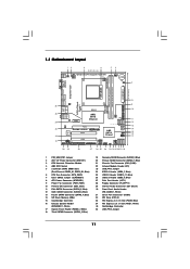
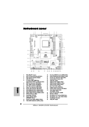
... (SATAII_1, Blue) 21 Chassis Fan Connector (CHA_FAN1) 22 Infrared Module Header (IR1) 23 USB_PW3 Jumper 24 USB 2.0 Header (USB6_7, Blue) 25 USB 2.0 Header (USB10_11, Blue) 26 USB 2.0 Header (USB8_9, Blue) 27 Print Port Header (LPT1) 28 Floppy Connector (FLOPPY1) 29 Internal Audio Connector...USB 3.0 SOCKET AM3 HDMI1 USB 2.0 T: USB2 B: USB3 USB 2.0: USB4 USB 3.0: USB5 36 35 34 33 32 31 USB_PW2 1 DDR3 1800 FSB2.6GHz USB 2.0 T: USB0 B: USB1 Top: RJ-45 DX10.1 PWR_FAN1 Top: LINE IN Center: FRONT Bottom: MIC IN AMD 880G IDE1 Chipset LAN PCIE1 AUDIO CODEC Super I/O PCIE2 880GMH-LE/USB3...
... (SATAII_1, Blue) 21 Chassis Fan Connector (CHA_FAN1) 22 Infrared Module Header (IR1) 23 USB_PW3 Jumper 24 USB 2.0 Header (USB6_7, Blue) 25 USB 2.0 Header (USB10_11, Blue) 26 USB 2.0 Header (USB8_9, Blue) 27 Print Port Header (LPT1) 28 Floppy Connector (FLOPPY1) 29 Internal Audio Connector...USB 3.0 SOCKET AM3 HDMI1 USB 2.0 T: USB2 B: USB3 USB 2.0: USB4 USB 3.0: USB5 36 35 34 33 32 31 USB_PW2 1 DDR3 1800 FSB2.6GHz USB 2.0 T: USB0 B: USB1 Top: RJ-45 DX10.1 PWR_FAN1 Top: LINE IN Center: FRONT Bottom: MIC IN AMD 880G IDE1 Chipset LAN PCIE1 AUDIO CODEC Super I/O PCIE2 880GMH-LE/USB3...

User Manual
Page 12
... 11 1 PS/2 Mouse Port (Green) 2 VGA/D-Sub Port * 3 LAN RJ-45 Port 4 Line In (Light Blue) * 5 Front Speaker (Lime) 6 Microphone (Pink) 7 USB 2.0 Ports (USB01) 10 9 8 7 8 USB 2.0 Port (USB4) 9 USB 3.0 Port (USB5) 10 USB 2.0 Ports (USB23) 11 VGA/HDMI Port 12 VGA/DVI-D Port 13 PS/2 Keyboard Port (Purple) * There are allowed to select "2 Channel...
... 11 1 PS/2 Mouse Port (Green) 2 VGA/D-Sub Port * 3 LAN RJ-45 Port 4 Line In (Light Blue) * 5 Front Speaker (Lime) 6 Microphone (Pink) 7 USB 2.0 Ports (USB01) 10 9 8 7 8 USB 2.0 Port (USB4) 9 USB 3.0 Port (USB5) 10 USB 2.0 Ports (USB23) 11 VGA/HDMI Port 12 VGA/DVI-D Port 13 PS/2 Keyboard Port (Purple) * There are allowed to select "2 Channel...

User Manual
Page 22
... +5VSB +5VSB (standby) for PS/2 or USB23 wake up events. Note: To select +5VSB, it down before you update the BIOS. If you select +5V_DUAL, USB devices can wake up the system first, and then shut it requires 2 Amp and higher standby current provided by power supply. Note: To select +5V_DUAL...
... +5VSB +5VSB (standby) for PS/2 or USB23 wake up events. Note: To select +5VSB, it down before you update the BIOS. If you select +5V_DUAL, USB devices can wake up the system first, and then shut it requires 2 Amp and higher standby current provided by power supply. Note: To select +5V_DUAL...

User Manual
Page 24
USB 2.0 Headers (9-pin USB6_7) (see p.11 No. 24) (9-pin USB8_9) (see p.11 No. 26) (9-pin USB10_11) (see p.11 No. 25) USB_PWR P-7 P+7 GND DUMMY 1 GND P+6 P-6 USB_PWR USB_PWR P-9 P+9 ... HD_AUDIO1) (see p.11, No. 30) GND PRESENCE# MIC_RET OUT_RET 1 OUT2_L J_SENSE OUT2_R MIC2_R MIC2_L Besides five default USB 2.0 ports on the I/O panel, there are three USB 2.0 headers on this motherboard. Each USB 2.0 header can support two USB 2.0 ports. This connector allows you to receive stereo audio input from sound sources such as a CD-ROM...
USB 2.0 Headers (9-pin USB6_7) (see p.11 No. 24) (9-pin USB8_9) (see p.11 No. 26) (9-pin USB10_11) (see p.11 No. 25) USB_PWR P-7 P+7 GND DUMMY 1 GND P+6 P-6 USB_PWR USB_PWR P-9 P+9 ... HD_AUDIO1) (see p.11, No. 30) GND PRESENCE# MIC_RET OUT_RET 1 OUT2_L J_SENSE OUT2_R MIC2_R MIC2_L Besides five default USB 2.0 ports on the I/O panel, there are three USB 2.0 headers on this motherboard. Each USB 2.0 header can support two USB 2.0 ports. This connector allows you to receive stereo audio input from sound sources such as a CD-ROM...

User Manual
Page 46
... tool and save the new BIOS file to your USB flash drive, floppy disk or hard drive, then you execute ASRock Instant Flash utility, the utility will show the BIOS files and their respective information. Please be noted that the USB flash drive or hard drive must use FAT32/16/... completes. 46 Setting wrong values in Flash ROM. CPU Configuration Chipset Configuration ACPI Configuration Storage Configuration PCIPnP Configuration Floppy Configuration SuperIO Configuration USB Configuration BIOS Update Utility ASRock Instant Flash Select Screen Select Item Enter Go to malfunction.
... tool and save the new BIOS file to your USB flash drive, floppy disk or hard drive, then you execute ASRock Instant Flash utility, the utility will show the BIOS files and their respective information. Please be noted that the USB flash drive or hard drive must use FAT32/16/... completes. 46 Setting wrong values in Flash ROM. CPU Configuration Chipset Configuration ACPI Configuration Storage Configuration PCIPnP Configuration Floppy Configuration SuperIO Configuration USB Configuration BIOS Update Utility ASRock Instant Flash Select Screen Select Item Enter Go to malfunction.

User Manual
Page 55
... options: [Enabled] - Please refer to enable or disable the USB 3.0 controller. 3.4.8 USB Configuration BIOS SETUP UTILITY Advanced USB Configuration USB Controller USB 2.0 Support Legacy USB Support USB 3.0 Controller [Enabled] [Enabled] [Enabled] [Enabled] USB Keyboard/Remote Power On [Disabled] USB Mouse Power On [Disabled] To enable or disable the onboard USB controllers. +F1 F9 F10 ESC Select Screen Select Item Change...
... options: [Enabled] - Please refer to enable or disable the USB 3.0 controller. 3.4.8 USB Configuration BIOS SETUP UTILITY Advanced USB Configuration USB Controller USB 2.0 Support Legacy USB Support USB 3.0 Controller [Enabled] [Enabled] [Enabled] [Enabled] USB Keyboard/Remote Power On [Disabled] USB Mouse Power On [Disabled] To enable or disable the onboard USB controllers. +F1 F9 F10 ESC Select Screen Select Item Change...

User Manual
Page 57
ROM C] [USB] Select Screen Select Item Enter Go to see the AddOn ROM information when the system boots, please select [Enabled]. Enabled: Displays OEM Logo instead of ...
ROM C] [USB] Select Screen Select Item Enter Go to see the AddOn ROM information when the system boots, please select [Enabled]. Enabled: Displays OEM Logo instead of ...
Quick Installation Guide
Page 2
... (SATAII_1, Blue) 21 Chassis Fan Connector (CHA_FAN1) 22 Infrared Module Header (IR1) 23 USB_PW3 Jumper 24 USB 2.0 Header (USB6_7, Blue) 25 USB 2.0 Header (USB10_11, Blue) 26 USB 2.0 Header (USB8_9, Blue) 27 Print Port Header (LPT1) 28 Floppy Connector (FLOPPY1) 29 Internal Audio ...PCI1-2) 33 PCI Express 2.0 x16 Slot (PCIE2; Blue) 34 PCI Express 2.0 x1 Slot (PCIE1; White) 35 Northbridge Controller 36 USB_PW2 Jumper 2 ASRock 880GMH-LE/USB3 Motherboard Motherboard Layout English 1 PS2_USB_PW1 Jumper 2 ATX 12V Power Connector (ATX12V1) 3 CPU Heatsink Retention Module 4 AM3 CPU Socket 5 2 x 240...
... (SATAII_1, Blue) 21 Chassis Fan Connector (CHA_FAN1) 22 Infrared Module Header (IR1) 23 USB_PW3 Jumper 24 USB 2.0 Header (USB6_7, Blue) 25 USB 2.0 Header (USB10_11, Blue) 26 USB 2.0 Header (USB8_9, Blue) 27 Print Port Header (LPT1) 28 Floppy Connector (FLOPPY1) 29 Internal Audio ...PCI1-2) 33 PCI Express 2.0 x16 Slot (PCIE2; Blue) 34 PCI Express 2.0 x1 Slot (PCIE1; White) 35 Northbridge Controller 36 USB_PW2 Jumper 2 ASRock 880GMH-LE/USB3 Motherboard Motherboard Layout English 1 PS2_USB_PW1 Jumper 2 ATX 12V Power Connector (ATX12V1) 3 CPU Heatsink Retention Module 4 AM3 CPU Socket 5 2 x 240...

Quick Installation Guide
Page 3
... for the LAN port LED indications. After restarting your change . 3 ASRock 880GMH-LE/USB3 Motherboard English I/O Panel 1 PS/2 Mouse Port (Green) 2 VGA/D-Sub Port * 3 LAN RJ-45 Port 4 Line In (Light Blue) * 5 Front Speaker (Lime) 6 Microphone (Pink) 7 USB 2.0 Ports (USB01) 8 USB 2.0 Port (USB4) 9 USB 3.0 Port (USB5) 10 USB 2.0 Ports (USB23) 11 VGA/HDMI Port 12 VGA/DVI-D Port...
... for the LAN port LED indications. After restarting your change . 3 ASRock 880GMH-LE/USB3 Motherboard English I/O Panel 1 PS/2 Mouse Port (Green) 2 VGA/D-Sub Port * 3 LAN RJ-45 Port 4 Line In (Light Blue) * 5 Front Speaker (Lime) 6 Microphone (Pink) 7 USB 2.0 Ports (USB01) 8 USB 2.0 Port (USB4) 9 USB 3.0 Port (USB5) 10 USB 2.0 Ports (USB23) 11 VGA/HDMI Port 12 VGA/DVI-D Port...

Quick Installation Guide
Page 6
... 1 x Floppy connector - 1 x IR header - 1 x Print port header - 1 x COM port header - Supports LAN Cable Detection I /O USB 3.0 Connector BIOS Feature Support CD - AMI Legal BIOS - ACPI 1.1 Compliance Wake Up Events - VCCM, NB Voltage Multi-adjustment - OEM and Trial; ...USB 3.0 port by Fresco FL1000G, supports USB 3.0 up to -Use USB 3.0 Port - 1 x RJ-45 LAN Port with LED (ACT/LINK LED and SPEED LED) - Front panel audio connector - 3 x USB 2.0 headers (support 6 USB 2.0 ports) - 8Mb AMI BIOS - SMBIOS 2.3.1 Support - Supports jumperfree - Trial) English 6 ASRock 880GMH-LE/USB3...
... 1 x Floppy connector - 1 x IR header - 1 x Print port header - 1 x COM port header - Supports LAN Cable Detection I /O USB 3.0 Connector BIOS Feature Support CD - AMI Legal BIOS - ACPI 1.1 Compliance Wake Up Events - VCCM, NB Voltage Multi-adjustment - OEM and Trial; ...USB 3.0 port by Fresco FL1000G, supports USB 3.0 up to -Use USB 3.0 Port - 1 x RJ-45 LAN Port with LED (ACT/LINK LED and SPEED LED) - Front panel audio connector - 3 x USB 2.0 headers (support 6 USB 2.0 ports) - 8Mb AMI BIOS - SMBIOS 2.3.1 Support - Supports jumperfree - Trial) English 6 ASRock 880GMH-LE/USB3...

Quick Installation Guide
Page 8
...can update your BIOS only in Flash ROM. For Windows® OS with 64-bit CPU, there is a revolutionary technology that the USB flash drive or hard drive must use Intelligent Energy Saver function, please enable Cool 'n' Quiet option in the BIOS setup in the support ... the CPU cores are idle. This motherboard supports Dual Channel Memory Technology. To use FAT32/16/12 file system. 8 ASRock 880GMH-LE/USB3 Motherboard English ASRock website: http://www.asrock.com 8. CAUTION! 1. You can press key during the POST or press key to BIOS setup menu to provide exceptional ...
...can update your BIOS only in Flash ROM. For Windows® OS with 64-bit CPU, there is a revolutionary technology that the USB flash drive or hard drive must use Intelligent Energy Saver function, please enable Cool 'n' Quiet option in the BIOS setup in the support ... the CPU cores are idle. This motherboard supports Dual Channel Memory Technology. To use FAT32/16/12 file system. 8 ASRock 880GMH-LE/USB3 Motherboard English ASRock website: http://www.asrock.com 8. CAUTION! 1. You can press key during the POST or press key to BIOS setup menu to provide exceptional ...

Quick Installation Guide
Page 19
... you to RAM) state. USB_PW3 Short pin2, pin3 to enable (see p.2, No. 7) Default Clear CMOS Note: CLRCMOS1 allows you select +5V_DUAL, USB devices can wake up the system under S3 (Suspend to clear the data in CMOS includes system setup information such as system password, date, time...pin jumper whose pin1 and pin2 are setup. However, please do not clear the CMOS right after you do the clear-CMOS action. 19 ASRock 880GMH-LE/USB3 Motherboard If you need to short pin2 and pin3 on pins, the jumper is "Short". 2.7 Jumpers Setup The illustration shows how jumpers are ...
... you to RAM) state. USB_PW3 Short pin2, pin3 to enable (see p.2, No. 7) Default Clear CMOS Note: CLRCMOS1 allows you select +5V_DUAL, USB devices can wake up the system under S3 (Suspend to clear the data in CMOS includes system setup information such as system password, date, time...pin jumper whose pin1 and pin2 are setup. However, please do not clear the CMOS right after you do the clear-CMOS action. 19 ASRock 880GMH-LE/USB3 Motherboard If you need to short pin2 and pin3 on pins, the jumper is "Short". 2.7 Jumpers Setup The illustration shows how jumpers are ...

Quick Installation Guide
Page 21
USB 2.0 Headers (9-pin USB6_7) (see p.2 No. 24) (9-pin USB8_9) (see p.2 No. 26) (9-pin USB10_11) (see p.2, No....: see p.2 No. 29) Front Panel Audio Header (9-pin HD_AUDIO1) (see p.2 No. 25) Besides five default USB 2.0 ports on the I/O panel, there are three USB 2.0 headers on this motherboard. This header supports an optional wireless transmitting and receiving infrared module. This connector allows you ... an interface for the front panel audio cable that allows convenient connection of audio devices. 21 ASRock 880GMH-LE/USB3 Motherboard English Each USB 2.0 header can support two...
USB 2.0 Headers (9-pin USB6_7) (see p.2 No. 24) (9-pin USB8_9) (see p.2 No. 26) (9-pin USB10_11) (see p.2, No....: see p.2 No. 29) Front Panel Audio Header (9-pin HD_AUDIO1) (see p.2 No. 25) Besides five default USB 2.0 ports on the I/O panel, there are three USB 2.0 headers on this motherboard. This header supports an optional wireless transmitting and receiving infrared module. This connector allows you ... an interface for the front panel audio cable that allows convenient connection of audio devices. 21 ASRock 880GMH-LE/USB3 Motherboard English Each USB 2.0 header can support two...


