
User Manual
Page 4
... 3.4 Advanced Screen 46 3.4.1 CPU Configuration 47 3.4.2 Chipset Configuration 48 3.4.3 ACPI Configuration 50 3.4.4 Storage Configuration 51 3.4.5 PCIPnP Configuration 53 3.4.6 Floppy Configuration 53 3.4.7 Super IO Configuration 54 3.4.8 USB Configuration 55 3.5 Hardware Health Event Monitoring Screen 56 3.6 Boot Screen 57 3.6.1 Boot Settings Configuration 57 3.7 Security Screen 58 3.8 Exit Screen 59 4 .
... 3.4 Advanced Screen 46 3.4.1 CPU Configuration 47 3.4.2 Chipset Configuration 48 3.4.3 ACPI Configuration 50 3.4.4 Storage Configuration 51 3.4.5 PCIPnP Configuration 53 3.4.6 Floppy Configuration 53 3.4.7 Super IO Configuration 54 3.4.8 USB Configuration 55 3.5 Hardware Health Event Monitoring Screen 56 3.6 Boot Screen 57 3.6.1 Boot Settings Configuration 57 3.7 Security Screen 58 3.8 Exit Screen 59 4 .

User Manual
Page 7
... FAN connector - 24 pin ATX power connector - 4 pin 12V power connector - Supports jumperfree - Explorer, AMD Fusion, ASRock Software Suite (CyberLink DVD Suite - Trial) 7 CD in header - VCCM, NB Voltage Multi-adjustment - Supports LAN Cable Detection I /O USB 3.0 Connector BIOS Feature Support CD - SMBIOS 2.3.1 Support - PCIE x1 Gigabit LAN 10/100/1000 Mb/s - Creative...
... FAN connector - 24 pin ATX power connector - 4 pin 12V power connector - Supports jumperfree - Explorer, AMD Fusion, ASRock Software Suite (CyberLink DVD Suite - Trial) 7 CD in header - VCCM, NB Voltage Multi-adjustment - Supports LAN Cable Detection I /O USB 3.0 Connector BIOS Feature Support CD - SMBIOS 2.3.1 Support - PCIE x1 Gigabit LAN 10/100/1000 Mb/s - Creative...

User Manual
Page 9
...flash utility embedded in advance. This convenient BIOS update tool allows you adopt. This motherboard supports Dual Channel Memory Technology. ASRock website http://www.asrock.com 4. Please visit our website for the latest information. 6. Due to update system BIOS without entering operating systems first... saving and improve power efficiency without preparing an additional floppy diskette or other words, it is a revolutionary technology that the USB flash drive or hard drive must use Intelligent Energy Saver function, please enable Cool 'n' Quiet option in the BIOS setup in...
...flash utility embedded in advance. This convenient BIOS update tool allows you adopt. This motherboard supports Dual Channel Memory Technology. ASRock website http://www.asrock.com 4. Please visit our website for the latest information. 6. Due to update system BIOS without entering operating systems first... saving and improve power efficiency without preparing an additional floppy diskette or other words, it is a revolutionary technology that the USB flash drive or hard drive must use Intelligent Energy Saver function, please enable Cool 'n' Quiet option in the BIOS setup in...
User Manual
Page 11
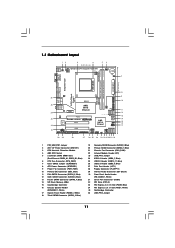
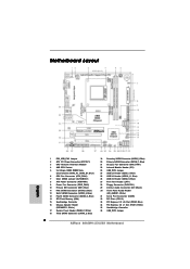
... (SATAII_1, Blue) 21 Chassis Fan Connector (CHA_FAN1) 22 Infrared Module Header (IR1) 23 USB_PW3 Jumper 24 USB 2.0 Header (USB6_7, Blue) 25 USB 2.0 Header (USB10_11, Blue) 26 USB 2.0 Header (USB8_9, Blue) 27 Print Port Header (LPT1) 28 Floppy Connector (FLOPPY1) 29 Internal Audio Connector...USB 3.0 SOCKET AM3 HDMI1 USB 2.0 T: USB2 B: USB3 USB 2.0: USB4 USB 3.0: USB5 36 35 34 33 32 31 USB_PW2 1 DDR3 1800 FSB2.6GHz USB 2.0 T: USB0 B: USB1 Top: RJ-45 DX10.1 PWR_FAN1 Top: LINE IN Center: FRONT Bottom: MIC IN AMD 880G IDE1 Chipset LAN PCIE1 AUDIO CODEC Super I/O PCIE2 880GMH-LE/USB3...
... (SATAII_1, Blue) 21 Chassis Fan Connector (CHA_FAN1) 22 Infrared Module Header (IR1) 23 USB_PW3 Jumper 24 USB 2.0 Header (USB6_7, Blue) 25 USB 2.0 Header (USB10_11, Blue) 26 USB 2.0 Header (USB8_9, Blue) 27 Print Port Header (LPT1) 28 Floppy Connector (FLOPPY1) 29 Internal Audio Connector...USB 3.0 SOCKET AM3 HDMI1 USB 2.0 T: USB2 B: USB3 USB 2.0: USB4 USB 3.0: USB5 36 35 34 33 32 31 USB_PW2 1 DDR3 1800 FSB2.6GHz USB 2.0 T: USB0 B: USB1 Top: RJ-45 DX10.1 PWR_FAN1 Top: LINE IN Center: FRONT Bottom: MIC IN AMD 880G IDE1 Chipset LAN PCIE1 AUDIO CODEC Super I/O PCIE2 880GMH-LE/USB3...

User Manual
Page 12
... 11 1 PS/2 Mouse Port (Green) 2 VGA/D-Sub Port * 3 LAN RJ-45 Port 4 Line In (Light Blue) * 5 Front Speaker (Lime) 6 Microphone (Pink) 7 USB 2.0 Ports (USB01) 10 9 8 7 8 USB 2.0 Port (USB4) 9 USB 3.0 Port (USB5) 10 USB 2.0 Ports (USB23) 11 VGA/HDMI Port 12 VGA/DVI-D Port 13 PS/2 Keyboard Port (Purple) * There are allowed to select "2 Channel...
... 11 1 PS/2 Mouse Port (Green) 2 VGA/D-Sub Port * 3 LAN RJ-45 Port 4 Line In (Light Blue) * 5 Front Speaker (Lime) 6 Microphone (Pink) 7 USB 2.0 Ports (USB01) 10 9 8 7 8 USB 2.0 Port (USB4) 9 USB 3.0 Port (USB5) 10 USB 2.0 Ports (USB23) 11 VGA/HDMI Port 12 VGA/DVI-D Port 13 PS/2 Keyboard Port (Purple) * There are allowed to select "2 Channel...

User Manual
Page 22
When you select +5V_DUAL, USB devices can wake up the system under S3 (Suspend to +5V. Note: To select +5VSB, it requires 2 Amp and higher standby current provided by power ...
When you select +5V_DUAL, USB devices can wake up the system under S3 (Suspend to +5V. Note: To select +5VSB, it requires 2 Amp and higher standby current provided by power ...

User Manual
Page 24
This connector allows you to receive stereo audio input from sound sources such as a CD-ROM, DVD-ROM, TV tuner card, or MPEG card. USB 2.0 Headers (9-pin USB6_7) (see p.11 No. 24) (9-pin USB8_9) (see p.11 No. 26) (9-pin USB10_11) (see p.11 No. 25) USB_PWR P-7 P+7 GND DUMMY 1 GND ... HD_AUDIO1) (see p.11, No. 30) GND PRESENCE# MIC_RET OUT_RET 1 OUT2_L J_SENSE OUT2_R MIC2_R MIC2_L Besides five default USB 2.0 ports on the I/O panel, there are three USB 2.0 headers on this motherboard. This is an interface for print port cable that allows convenient connection and control of printer ...
This connector allows you to receive stereo audio input from sound sources such as a CD-ROM, DVD-ROM, TV tuner card, or MPEG card. USB 2.0 Headers (9-pin USB6_7) (see p.11 No. 24) (9-pin USB8_9) (see p.11 No. 26) (9-pin USB10_11) (see p.11 No. 25) USB_PWR P-7 P+7 GND DUMMY 1 GND ... HD_AUDIO1) (see p.11, No. 30) GND PRESENCE# MIC_RET OUT_RET 1 OUT2_L J_SENSE OUT2_R MIC2_R MIC2_L Besides five default USB 2.0 ports on the I/O panel, there are three USB 2.0 headers on this motherboard. This is an interface for print port cable that allows convenient connection and control of printer ...

User Manual
Page 46
..., PCIPnP Configuration, Floppy configuration, SuperIO Configuration, and USB Configuration. CPU Configuration Chipset Configuration ACPI Configuration Storage Configuration PCIPnP Configuration Floppy Configuration SuperIO Configuration USB Configuration BIOS Update Utility ASRock Instant Flash Select Screen Select Item Enter Go to update... utility will show the BIOS files and their respective information. ASRock Instant Flash ASRock Instant Flash is a BIOS flash utility embedded in this section, you can update your USB flash drive, floppy disk or hard drive, then you may...
..., PCIPnP Configuration, Floppy configuration, SuperIO Configuration, and USB Configuration. CPU Configuration Chipset Configuration ACPI Configuration Storage Configuration PCIPnP Configuration Floppy Configuration SuperIO Configuration USB Configuration BIOS Update Utility ASRock Instant Flash Select Screen Select Item Enter Go to update... utility will show the BIOS files and their respective information. ASRock Instant Flash ASRock Instant Flash is a BIOS flash utility embedded in this section, you can update your USB flash drive, floppy disk or hard drive, then you may...

User Manual
Page 55
... are not allowed to below descriptions for the details of USB controller. 3.4.8 USB Configuration BIOS SETUP UTILITY Advanced USB Configuration USB Controller USB 2.0 Support Legacy USB Support USB 3.0 Controller [Enabled] [Enabled] [Enabled] [Enabled] USB Keyboard/Remote Power On [Disabled] USB Mouse Power On [Disabled] To enable or disable the onboard USB controllers. +F1 F9 F10 ESC Select Screen Select Item...
... are not allowed to below descriptions for the details of USB controller. 3.4.8 USB Configuration BIOS SETUP UTILITY Advanced USB Configuration USB Controller USB 2.0 Support Legacy USB Support USB 3.0 Controller [Enabled] [Enabled] [Enabled] [Enabled] USB Keyboard/Remote Power On [Disabled] USB Mouse Power On [Disabled] To enable or disable the onboard USB controllers. +F1 F9 F10 ESC Select Screen Select Item...

User Manual
Page 57
... Logo" but you to configure the boot settings and the boot priority. CD - The default value is [Enabled]. 57 The default value is [Enabled]. ROM C] [USB] Select Screen Select Item Enter Go to enable or disable OEM Logo. Configuration options: [Enabled] and [Disabled]. 3.6 Boot Screen In this section, it will display...
... Logo" but you to configure the boot settings and the boot priority. CD - The default value is [Enabled]. 57 The default value is [Enabled]. ROM C] [USB] Select Screen Select Item Enter Go to enable or disable OEM Logo. Configuration options: [Enabled] and [Disabled]. 3.6 Boot Screen In this section, it will display...
Quick Installation Guide
Page 2
... Blue) 21 Chassis Fan Connector (CHA_FAN1) 22 Infrared Module Header (IR1) 23 USB_PW3 Jumper 24 USB 2.0 Header (USB6_7, Blue) 25 USB 2.0 Header (USB10_11, Blue) 26 USB 2.0 Header (USB8_9, Blue) 27 Print Port Header (LPT1) 28 Floppy Connector (FLOPPY1) 29 ...Internal Audio Connector: CD1 (Black) 30 Front Panel Audio Header (HD_AUDIO1, White) 31 Serial Port Connector (COM1) 32 PCI Slots (PCI1-2) 33 PCI Express 2.0 x16 Slot (PCIE2; White) 35 Northbridge Controller 36 USB_PW2 Jumper 2 ASRock 880GMH-LE/USB3...
... Blue) 21 Chassis Fan Connector (CHA_FAN1) 22 Infrared Module Header (IR1) 23 USB_PW3 Jumper 24 USB 2.0 Header (USB6_7, Blue) 25 USB 2.0 Header (USB10_11, Blue) 26 USB 2.0 Header (USB8_9, Blue) 27 Print Port Header (LPT1) 28 Floppy Connector (FLOPPY1) 29 ...Internal Audio Connector: CD1 (Black) 30 Front Panel Audio Header (HD_AUDIO1, White) 31 Serial Port Connector (COM1) 32 PCI Slots (PCI1-2) 33 PCI Express 2.0 x16 Slot (PCIE2; White) 35 Northbridge Controller 36 USB_PW2 Jumper 2 ASRock 880GMH-LE/USB3...

Quick Installation Guide
Page 3
... to the front panel audio header. After restarting your change . 3 ASRock 880GMH-LE/USB3 Motherboard English I/O Panel 1 PS/2 Mouse Port (Green) 2 VGA/D-Sub Port * 3 LAN RJ-45 Port 4 Line In (Light Blue) * 5 Front Speaker (Lime) 6 Microphone (Pink) 7 USB 2.0 Ports (USB01) 8 USB 2.0 Port (USB4) 9 USB 3.0 Port (USB5) 10 USB 2.0 Ports (USB23) 11 VGA/HDMI Port 12 VGA/DVI-D Port...
... to the front panel audio header. After restarting your change . 3 ASRock 880GMH-LE/USB3 Motherboard English I/O Panel 1 PS/2 Mouse Port (Green) 2 VGA/D-Sub Port * 3 LAN RJ-45 Port 4 Line In (Light Blue) * 5 Front Speaker (Lime) 6 Microphone (Pink) 7 USB 2.0 Ports (USB01) 8 USB 2.0 Port (USB4) 9 USB 3.0 Port (USB5) 10 USB 2.0 Ports (USB23) 11 VGA/HDMI Port 12 VGA/DVI-D Port...

Quick Installation Guide
Page 6
... - Trial) English 6 ASRock 880GMH-LE/USB3 Motherboard Realtek RTL8111E - AMI Legal BIOS - SMBIOS 2.3.1 Support - VCCM, NB Voltage Multi-adjustment - Supports LAN Cable Detection I /O USB 3.0 Connector BIOS Feature Support CD - Front panel audio connector - 3 x USB 2.0 headers (support 6 USB 2.0 ports) - 8Mb ... PS/2 Mouse Port - 1 x PS/2 Keyboard Port - 1 x VGA/D-Sub Port - 1 x VGA/DVI-D Port - 1 x HDMI Port - 5 x Ready-to-Use USB 2.0 Ports - 1 x Ready-to 5Gb/s - 6 x Serial ATAII 3.0Gb/s connectors, support RAID (RAID 0, RAID 1, RAID 10 and JBOD), NCQ, AHCI and "Hot Plug...
... - Trial) English 6 ASRock 880GMH-LE/USB3 Motherboard Realtek RTL8111E - AMI Legal BIOS - SMBIOS 2.3.1 Support - VCCM, NB Voltage Multi-adjustment - Supports LAN Cable Detection I /O USB 3.0 Connector BIOS Feature Support CD - Front panel audio connector - 3 x USB 2.0 headers (support 6 USB 2.0 ports) - 8Mb ... PS/2 Mouse Port - 1 x PS/2 Keyboard Port - 1 x VGA/D-Sub Port - 1 x VGA/DVI-D Port - 1 x HDMI Port - 5 x Ready-to-Use USB 2.0 Ports - 1 x Ready-to 5Gb/s - 6 x Serial ATAII 3.0Gb/s connectors, support RAID (RAID 0, RAID 1, RAID 10 and JBOD), NCQ, AHCI and "Hot Plug...

Quick Installation Guide
Page 8
... tool which allows you want to adopt DDR3 1800/1600 memory module on page 27 of output phases to your USB flash drive, floppy disk or hard drive, then you can also connect SATA hard disk to change. In other complicated flash utility. Please.... Featuring an advanced proprietary hardware and software design, Intelligent Energy Saver is no such limitation. 5. To use FAT32/16/12 file system. 8 ASRock 880GMH-LE/USB3 Motherboard English ASRock Instant Flash is supported depends on the AM3 CPU you can reduce the number of "User Manual" in the support CD to adjust your...
... tool which allows you want to adopt DDR3 1800/1600 memory module on page 27 of output phases to your USB flash drive, floppy disk or hard drive, then you can also connect SATA hard disk to change. In other complicated flash utility. Please.... Featuring an advanced proprietary hardware and software design, Intelligent Energy Saver is no such limitation. 5. To use FAT32/16/12 file system. 8 ASRock 880GMH-LE/USB3 Motherboard English ASRock Instant Flash is supported depends on the AM3 CPU you can reduce the number of "User Manual" in the support CD to adjust your...

Quick Installation Guide
Page 19
.... Note: To select +5VSB, it requires 2 Amp and higher standby current provided by power supply. However, please do the clear-CMOS action. 19 ASRock 880GMH-LE/USB3 Motherboard When the jumper cap is placed on pins, the jumper is placed on these 2 pins. Note: To select +5VSB, it requires 2 Amp ..., pin3 to enable (see p.2, No. 7) Default Clear CMOS Note: CLRCMOS1 allows you do not clear the CMOS right after you select +5V_DUAL, USB devices can wake up events. To support ErP/EuP requirement, please set this jumper to default setup, please turn off the computer and unplug the...
.... Note: To select +5VSB, it requires 2 Amp and higher standby current provided by power supply. However, please do the clear-CMOS action. 19 ASRock 880GMH-LE/USB3 Motherboard When the jumper cap is placed on pins, the jumper is placed on these 2 pins. Note: To select +5VSB, it requires 2 Amp ..., pin3 to enable (see p.2, No. 7) Default Clear CMOS Note: CLRCMOS1 allows you do not clear the CMOS right after you select +5V_DUAL, USB devices can wake up events. To support ErP/EuP requirement, please set this jumper to default setup, please turn off the computer and unplug the...

Quick Installation Guide
Page 21
...front panel audio cable that allows convenient connection of audio devices. 21 ASRock 880GMH-LE/USB3 Motherboard English This header supports an optional wireless transmitting and receiving infrared module. Each USB 2.0 header can support two USB 2.0 ports. Print Port Header (25-pin LPT1) (see p.2 ...CD1: see p.2 No. 29) Front Panel Audio Header (9-pin HD_AUDIO1) (see p.2 No. 25) Besides five default USB 2.0 ports on the I/O panel, there are three USB 2.0 headers on this motherboard. USB 2.0 Headers (9-pin USB6_7) (see p.2 No. 24) (9-pin USB8_9) (see p.2 No. 26) (9-pin USB10_11)...
...front panel audio cable that allows convenient connection of audio devices. 21 ASRock 880GMH-LE/USB3 Motherboard English This header supports an optional wireless transmitting and receiving infrared module. Each USB 2.0 header can support two USB 2.0 ports. Print Port Header (25-pin LPT1) (see p.2 ...CD1: see p.2 No. 29) Front Panel Audio Header (9-pin HD_AUDIO1) (see p.2 No. 25) Besides five default USB 2.0 ports on the I/O panel, there are three USB 2.0 headers on this motherboard. USB 2.0 Headers (9-pin USB6_7) (see p.2 No. 24) (9-pin USB8_9) (see p.2 No. 26) (9-pin USB10_11)...


