User Manual
Page 3
... ATAII (SATAII) Hard Disks Installation 24 2.12 Driver Installation Guide 24 2.13 HDMR Card and Driver Installation 24 2.14 Untied Overclocking Technology 24 3 BIOS SETUP UTILITY 25 3.1 Introduction 25 3.1.1 BIOS Menu Bar 25 3.1.2 Navigation Keys 26 3.2 Main Screen 26 3.3 Advanced Screen 26 3.3.1 CPU Configuration 27 3.3.2 Chipset Configuration 29 3.3.3 ACPI Configuration 31 3.3.4 IDE...
... ATAII (SATAII) Hard Disks Installation 24 2.12 Driver Installation Guide 24 2.13 HDMR Card and Driver Installation 24 2.14 Untied Overclocking Technology 24 3 BIOS SETUP UTILITY 25 3.1 Introduction 25 3.1.1 BIOS Menu Bar 25 3.1.2 Navigation Keys 26 3.2 Main Screen 26 3.3 Advanced Screen 26 3.3.1 CPU Configuration 27 3.3.2 Chipset Configuration 29 3.3.3 ACPI Configuration 31 3.3.4 IDE...
User Manual
Page 5
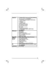
It delivers excellent performance with robust design conforming to ASRock's commitment to BIOS setup and information of the Support CD. ASRock website http://www.asrock.com 1.1 Package Contents ASRock 775i945GZ Motherboard (Micro ATX Form Factor: 9.6-in x 8.6-in Floppy Drive One Serial ATA (SATA) Data Cable...subject to the hardware installation. Chapter 1 Introduction Thank you for a 3.5-in , 24.4 cm x 21.8 cm) ASRock 775i945GZ Quick Installation Guide ASRock 775i945GZ Support CD (including LGA 775 CPU Installation Live Demo) One 80-conductor Ultra ATA 66/100 IDE Ribbon Cable One ...
It delivers excellent performance with robust design conforming to ASRock's commitment to BIOS setup and information of the Support CD. ASRock website http://www.asrock.com 1.1 Package Contents ASRock 775i945GZ Motherboard (Micro ATX Form Factor: 9.6-in x 8.6-in Floppy Drive One Serial ATA (SATA) Data Cable...subject to the hardware installation. Chapter 1 Introduction Thank you for a 3.5-in , 24.4 cm x 21.8 cm) ASRock 775i945GZ Quick Installation Guide ASRock 775i945GZ Support CD (including LGA 775 CPU Installation Live Demo) One 80-conductor Ultra ATA 66/100 IDE Ribbon Cable One ...
User Manual
Page 7
... Monitor OS Certifications - 4 x SATAII 3.0 Gb/s connectors (No Support for RAID and "Hot Plug" functions) (see CAUTION 9) - 4Mb AMI BIOS - Chassis Fan Tachometer - Voltage Monitoring: +12V, +5V, +3.3V, Vcore - FCC, CE, WHQL 7 Front panel audio connector - 2 x... (supports 2 x IDE devices) - 1 x Floppy connector - 1 x IR header - 1 x COM port header - Supports "Plug and Play" - AMI Legal BIOS - Supports jumperfree - AMBIOS 2.3.1 Support - CD in header - CPU Fan Tachometer - Drivers, Utilities, AntiVirus Software (Trial Version) - Microsoft® Windows® 2000/XP...
... Monitor OS Certifications - 4 x SATAII 3.0 Gb/s connectors (No Support for RAID and "Hot Plug" functions) (see CAUTION 9) - 4Mb AMI BIOS - Chassis Fan Tachometer - Voltage Monitoring: +12V, +5V, +3.3V, Vcore - FCC, CE, WHQL 7 Front panel audio connector - 2 x... (supports 2 x IDE devices) - 1 x Floppy connector - 1 x IR header - 1 x COM port header - Supports "Plug and Play" - AMI Legal BIOS - Supports jumperfree - AMBIOS 2.3.1 Support - CD in header - CPU Fan Tachometer - Drivers, Utilities, AntiVirus Software (Trial Version) - Microsoft® Windows® 2000/XP...
User Manual
Page 11
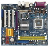
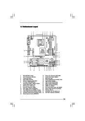
... 28 27 26 25 Top: LINE IN Center: FRONT Bottom: MIC IN To p : REAR SPK Center: SIDE SPK Bottom: CTR BASS Presler 775i945GZ USB 2.0 T: USB2 B: USB3 USB 2.0 T: USB0 B: USB1 Top: RJ-45 Intel 945GZ Chipset Conroe ATXPWR1 AGI_EXPRESS1 PCI EXPRESS PCI1 PCI LAN RoHS... 1 PS2_USB_PWR1 Jumper 15 Chassis Fan Connector (CHA_FAN1) 2 ATX 12V Connector (ATX12V1) 16 System Panel Header (PANEL1) 3 775-Pin CPU Socket 17 BIOS FWH Chip 4 North Bridge Controller 18 Primary SATAII Connector (SATAII_1; Orange) 27 AGI Express Slot (PCI Express x4) 13 Secondary SATAII Connector (SATAII_2;...
... 28 27 26 25 Top: LINE IN Center: FRONT Bottom: MIC IN To p : REAR SPK Center: SIDE SPK Bottom: CTR BASS Presler 775i945GZ USB 2.0 T: USB2 B: USB3 USB 2.0 T: USB0 B: USB1 Top: RJ-45 Intel 945GZ Chipset Conroe ATXPWR1 AGI_EXPRESS1 PCI EXPRESS PCI1 PCI LAN RoHS... 1 PS2_USB_PWR1 Jumper 15 Chassis Fan Connector (CHA_FAN1) 2 ATX 12V Connector (ATX12V1) 16 System Panel Header (PANEL1) 3 775-Pin CPU Socket 17 BIOS FWH Chip 4 North Bridge Controller 18 Primary SATAII Connector (SATAII_1; Orange) 27 AGI Express Slot (PCI Express x4) 13 Secondary SATAII Connector (SATAII_2;...

User Manual
Page 18
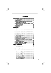
... for later use . Step 2. Step 3. Remove the bracket facing the slot that have the 32-bit PCI interface. Please make sure to set the BIOS onboard VGA selection into "Enabled" if you want this motherboard. Step 4. Fasten the card to the chassis with the slot and press firmly until the...support Surround Display. Align the card connector with screws. 18 Keep the screws for AGI Express Slot (PCI Express x4)" on PCI Express VGA card, BIOS setup will be the primary VGA card. For the information of the expansion card and make sure that the power supply is switched off or...
... for later use . Step 2. Step 3. Remove the bracket facing the slot that have the 32-bit PCI interface. Please make sure to set the BIOS onboard VGA selection into "Enabled" if you want this motherboard. Step 4. Fasten the card to the chassis with the slot and press firmly until the...support Surround Display. Align the card connector with screws. 18 Keep the screws for AGI Express Slot (PCI Express x4)" on PCI Express VGA card, BIOS setup will be the primary VGA card. For the information of the expansion card and make sure that the power supply is switched off or...
User Manual
Page 19
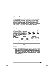
... Note: To select +5VSB, it requires 2 Amp and higher standby current provided by power supply. To clear and reset the system parameters to ASRock patented AGI Express Technology, this motherboard to short 2 pins on PCI Express VGA card, you can easily enjoy the benefits of Surround Display feature...CMOS (CLRCMOS1, 2-pin jumper) (see p.11 No. 1) 2_3 Short pin2, pin3 to clear the data in CMOS. Please make sure to set the BIOS onboard VGA selection into "Enabled", and start your computer with onboard VGA if you to enable +5VSB (standby) for 5 seconds. 19 2.7 Surround Display ...
... Note: To select +5VSB, it requires 2 Amp and higher standby current provided by power supply. To clear and reset the system parameters to ASRock patented AGI Express Technology, this motherboard to short 2 pins on PCI Express VGA card, you can easily enjoy the benefits of Surround Display feature...CMOS (CLRCMOS1, 2-pin jumper) (see p.11 No. 1) 2_3 Short pin2, pin3 to clear the data in CMOS. Please make sure to set the BIOS onboard VGA selection into "Enabled", and start your computer with onboard VGA if you to enable +5VSB (standby) for 5 seconds. 19 2.7 Surround Display ...

User Manual
Page 21
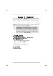
... MIC2_L This is an interface for front panel audio cable that allows convenient connection and control of audio devices. 1. Connect Ground (GND) to OUT2_L. Enter BIOS Setup Utility. Connect Mic_IN (MIC) to [Enabled]. 21 Set the Front Panel Control option from sound sources such as below: A. USB 2.0 Headers (9-pin USB67) (see...
... MIC2_L This is an interface for front panel audio cable that allows convenient connection and control of audio devices. 1. Connect Ground (GND) to OUT2_L. Enter BIOS Setup Utility. Connect Mic_IN (MIC) to [Enabled]. 21 Set the Front Panel Control option from sound sources such as below: A. USB 2.0 Headers (9-pin USB67) (see...
User Manual
Page 24
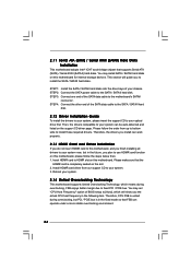
... below then. 1. Then, the drivers compatible to install the SATA / SATAII hard disks. STEP 1: Install the SATA / SATAII hard disks into the drive bays of BIOS setup to [Auto], which means during overclocking, but in the future, you the actual CPU host frequency in the fixed mode so that supports Serial...
... below then. 1. Then, the drivers compatible to install the SATA / SATAII hard disks. STEP 1: Install the SATA / SATAII hard disks into the drive bays of BIOS setup to [Auto], which means during overclocking, but in the future, you the actual CPU host frequency in the fixed mode so that supports Serial...
User Manual
Page 25
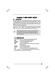
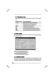
... is constantly being updated, the following selections: Main To set up the system time/date information Advanced To set up the advanced BIOS features PCIPnP To set up the PCI features Boot To set up the default system device to locate and load the Operating System Security To ..., and then press to get into the sub screen. 25 If you start up the chipset features Exit To exit the current screen or the BIOS SETUP UTILITY Use < > key or < > key to choose among the selections on . You may not exactly match what you see on the motherboard stores the...
... is constantly being updated, the following selections: Main To set up the system time/date information Advanced To set up the advanced BIOS features PCIPnP To set up the PCI features Boot To set up the default system device to locate and load the Operating System Security To ..., and then press to get into the sub screen. 25 If you start up the chipset features Exit To exit the current screen or the BIOS SETUP UTILITY Use < > key or < > key to choose among the selections on . You may not exactly match what you see on the motherboard stores the...
User Manual
Page 26
... screen 3.2 Main Screen When you may set the configurations for the following table for all the settings To save changes and exit the BIOS SETUP UTILITY To jump to configure system Time. +Tab F1 F9 F10 ESC Select Screen Select Item Change Field Select Field General Help ... UTILITY Main Advanced H/W Monitor Boot Security Exit System Overview System Time System Date [14:00:09] [Fri 05/26/2006] BIOS Version : 775i945GZ BIOS P1.00 Processor Type : Intel (R) CPU 3.40 GHz (64bit supported) Processor Speed : 3400 MHz Microcode Update : F34/17 Cache Size : 1024KB Total Memory ...
... screen 3.2 Main Screen When you may set the configurations for the following table for all the settings To save changes and exit the BIOS SETUP UTILITY To jump to configure system Time. +Tab F1 F9 F10 ESC Select Screen Select Item Change Field Select Field General Help ... UTILITY Main Advanced H/W Monitor Boot Security Exit System Overview System Time System Date [14:00:09] [Fri 05/26/2006] BIOS Version : 775i945GZ BIOS P1.00 Processor Type : Intel (R) CPU 3.40 GHz (64bit supported) Processor Speed : 3400 MHz Microcode Update : F34/17 Cache Size : 1024KB Total Memory ...
User Manual
Page 27
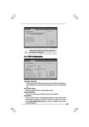
... Guard Enable or disable the feature of this section may cause system to allow you will show in the following item. BIOS SETUP UTILITY Main Advanced H/W Monitor Boot Security Exit Advanced Settings WARNING : Setting wrong values in below sections may cause the... system to malfunction. 3.3.1 CPU Configuration BIOS SETUP UTILITY Advanced CPU Configuration CPU Host Frequency Actual Frequency (MHz) Boot Failure Guard Spread Spectrum [Auto] [200] [Enabled] [Auto...
... Guard Enable or disable the feature of this section may cause system to allow you will show in the following item. BIOS SETUP UTILITY Main Advanced H/W Monitor Boot Security Exit Advanced Settings WARNING : Setting wrong values in below sections may cause the... system to malfunction. 3.3.1 CPU Configuration BIOS SETUP UTILITY Advanced CPU Configuration CPU Host Frequency Actual Frequency (MHz) Boot Failure Guard Spread Spectrum [Auto] [200] [Enabled] [Auto...
User Manual
Page 29
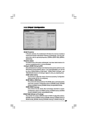
... RAS# Precharge", and "DRAM RAS# Activate to Precharge" appear to allow you will detect the memory module(s) inserted and assigns appropriate frequency automatically. 3.3.2 Chipset Configuration BIOS SETUP UTILITY Advanced Chipset Configuration DRAM Frequency [Auto] Flexibility Option [Disabled] Configure DRAM Timing by SPD Select [Enabled] will allow better tolerance for TRAS. DRAM...
... RAS# Precharge", and "DRAM RAS# Activate to Precharge" appear to allow you will detect the memory module(s) inserted and assigns appropriate frequency automatically. 3.3.2 Chipset Configuration BIOS SETUP UTILITY Advanced Chipset Configuration DRAM Frequency [Auto] Flexibility Option [Disabled] Configure DRAM Timing by SPD Select [Enabled] will allow better tolerance for TRAS. DRAM...
User Manual
Page 31
... ESC Select Screen Select Item Change Option General Help Load Defaults Save and Exit Exit v02.54 (C) Copyright 1985-2005, American Megatrends, Inc. 3.3.3 ACPI Configuration BIOS SETUP UTILITY Advanced ACPI Configuration Suspend To RAM Restore on AC/Power Loss This allows you to select whether to auto-detect or disable the...
... ESC Select Screen Select Item Change Option General Help Load Defaults Save and Exit Exit v02.54 (C) Copyright 1985-2005, American Megatrends, Inc. 3.3.3 ACPI Configuration BIOS SETUP UTILITY Advanced ACPI Configuration Suspend To RAM Restore on AC/Power Loss This allows you to select whether to auto-detect or disable the...
User Manual
Page 32
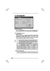
3.3.4 IDE Configuration BIOS SETUP UTILITY Advanced IDE Configuration ATA/IDE Configuration SATAII_1 SATAII_2 SATAII_3 SATAII_4 IDE1 Master IDE1 Slave [Enhanced] [Hard Disk] [Not Detected] [Not Detected] [Not Detected] [...
3.3.4 IDE Configuration BIOS SETUP UTILITY Advanced IDE Configuration ATA/IDE Configuration SATAII_1 SATAII_2 SATAII_3 SATAII_4 IDE1 Master IDE1 Slave [Enhanced] [Hard Disk] [Not Detected] [Not Detected] [Not Detected] [...
User Manual
Page 33
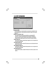
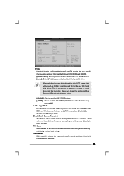
BIOS SETUP UTILITY Advanced Primary IDE Master Device Vendor Size LBA Mode Block Mode PIO Mode Async DMA Ultra DMA S.M.A.R.T. This is used for IDE CD/... the Primary IDE hard disk drives to set the PIO mode to automatically detect the hard disk drive. After selecting the hard disk information into BIOS, use of IDE device. [Auto]: Select [Auto] to enhance hard disk performance by reading or writing more data during each transfer. LBA/Large Mode Use...
BIOS SETUP UTILITY Advanced Primary IDE Master Device Vendor Size LBA Mode Block Mode PIO Mode Async DMA Ultra DMA S.M.A.R.T. This is used for IDE CD/... the Primary IDE hard disk drives to set the PIO mode to automatically detect the hard disk drive. After selecting the hard disk information into BIOS, use of IDE device. [Auto]: Select [Auto] to enhance hard disk performance by reading or writing more data during each transfer. LBA/Large Mode Use...
User Manual
Page 34
... installed PCI expansion cards' specifications require other settings. PCI IDE BusMaster Use this item to maximize the IDE hard disk data transfer rate. 3.3.5 PCIPnP Configuration BIOS SETUP UTILITY Advanced Advanced PCI / PnP Settings WARNING: Setting wrong values in units of PCI clocks for PCI device latency timer register. +F1 F9 F10...
... installed PCI expansion cards' specifications require other settings. PCI IDE BusMaster Use this item to maximize the IDE hard disk data transfer rate. 3.3.5 PCIPnP Configuration BIOS SETUP UTILITY Advanced Advanced PCI / PnP Settings WARNING: Setting wrong values in units of PCI clocks for PCI device latency timer register. +F1 F9 F10...
User Manual
Page 35
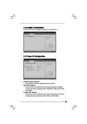
... Help Load Defaults Save and Exit Exit v02.54 (C) Copyright 1985-2005, American Megatrends, Inc. 3.3.7 Super IO Configuration BIOS SETUP UTILITY Advanced Configure Super IO Chipset OnBoard Floppy Controller Serial Port Address Infrared Port Address Parallel Port Address Parallel Port Mode... 1985-2005, American Megatrends, Inc. Infrared Port Address Use this item to set the address for the onboard serial port or disable it . BIOS SETUP UTILITY Advanced Floppy Configuration Floppy A [1.44 MB 312"] Select the type of your floppy drive. Configuration options: [Disabled], [2F8 / ...
... Help Load Defaults Save and Exit Exit v02.54 (C) Copyright 1985-2005, American Megatrends, Inc. 3.3.7 Super IO Configuration BIOS SETUP UTILITY Advanced Configure Super IO Chipset OnBoard Floppy Controller Serial Port Address Infrared Port Address Parallel Port Address Parallel Port Mode... 1985-2005, American Megatrends, Inc. Infrared Port Address Use this item to set the address for the onboard serial port or disable it . BIOS SETUP UTILITY Advanced Floppy Configuration Floppy A [1.44 MB 312"] Select the type of your floppy drive. Configuration options: [Disabled], [2F8 / ...
User Manual
Page 36
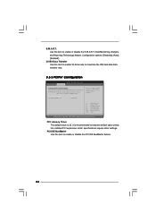
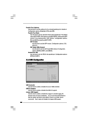
... is set to set the operation mode of USB controller. Configuration options: [Normal], [Bi-Directional], and [ECP+EPP]. Configuration options: [IRQ5] and [IRQ7]. 3.3.8 USB Configuration BIOS SETUP UTILITY Advanced USB Configuration USB Controller USB 2.0 Support Legacy USB Support [Enabled] [Enabled] [Disabled] To enable or disable the onboard USB controllers. +F1 F9...
... is set to set the operation mode of USB controller. Configuration options: [Normal], [Bi-Directional], and [ECP+EPP]. Configuration options: [IRQ5] and [IRQ7]. 3.3.8 USB Configuration BIOS SETUP UTILITY Advanced USB Configuration USB Controller USB 2.0 Support Legacy USB Support [Enabled] [Enabled] [Disabled] To enable or disable the onboard USB controllers. +F1 F9...

User Manual
Page 37
The default value is [Fast]. The default value is [Disabled]. BIOS SETUP UTILITY Main Advanced H/W Monitor Boot Security Exit Hardware Health Event Monitoring CPU Temperature M / B Temperature : 37 C / 98 F : 31 C / 87 F Target Fan Speed Fast Middle Slow ...
The default value is [Fast]. The default value is [Disabled]. BIOS SETUP UTILITY Main Advanced H/W Monitor Boot Security Exit Hardware Health Event Monitoring CPU Temperature M / B Temperature : 37 C / 98 F : 31 C / 87 F Target Fan Speed Fast Middle Slow ...
User Manual
Page 38
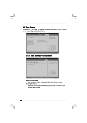
... Help F9 Load Defaults F10 Save and Exit ESC Exit v02.54 (C) Copyright 1985-2005, American Megatrends, Inc. 3.5.1 Boot Settings Configuration BIOS SETUP UTILITY Boot Boot Settings Configuration Boot From Network Bootup Num-Lock [Disabled] [On] To enable or disable the boot from network feature... Up Num-Lock If this item to [On], it will automatically activate the Numeric Lock function after boot-up. 38 Main Advanced BIOS SETUP UTILITY H/W Monitor Boot Security Exit Boot Settings Boot Settings Configuration Configure Settings during System Boot. 1st Boot Device 2nd Boot Device ...
... Help F9 Load Defaults F10 Save and Exit ESC Exit v02.54 (C) Copyright 1985-2005, American Megatrends, Inc. 3.5.1 Boot Settings Configuration BIOS SETUP UTILITY Boot Boot Settings Configuration Boot From Network Bootup Num-Lock [Disabled] [On] To enable or disable the boot from network feature... Up Num-Lock If this item to [On], it will automatically activate the Numeric Lock function after boot-up. 38 Main Advanced BIOS SETUP UTILITY H/W Monitor Boot Security Exit Boot Settings Boot Settings Configuration Configure Settings during System Boot. 1st Boot Device 2nd Boot Device ...


