
User Manual
Page 13
... strap or touch a safety grounded object before you uninstall any motherboard settings. 1. Unplug the power cord from the power supply. Chapter 2 Installation 775XFire-eSATA2+ is detached from the wall socket before installing or removing the motherboard. Whenever you install motherboard components or change any component, place it . Failure to do not touch the...
... strap or touch a safety grounded object before you uninstall any motherboard settings. 1. Unplug the power cord from the power supply. Chapter 2 Installation 775XFire-eSATA2+ is detached from the wall socket before installing or removing the motherboard. Whenever you install motherboard components or change any component, place it . Failure to do not touch the...

User Manual
Page 14
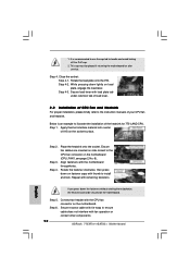
...be seriously damaged. Rotate the load lever to fully open position at approximately 135 degrees. Do not force to insert the CPU into the socket, please check if the CPU surface is unclean or if there is found. Pin1 orientation key notch orientation key notch Pin1 alignment key ...alignment key 775-LAND CPU 775-Pin Socket 14 black line black line Step 1. Hold the CPU by depressing down and out on the socket. Orient the CPU with black lines. Open the socket: Step 1-1. Step 1-3. Rotate the load plate to fully open position ...
...be seriously damaged. Rotate the load lever to fully open position at approximately 135 degrees. Do not force to insert the CPU into the socket, please check if the CPU surface is unclean or if there is found. Pin1 orientation key notch orientation key notch Pin1 alignment key ...alignment key 775-LAND CPU 775-Pin Socket 14 black line black line Step 1. Hold the CPU by depressing down and out on the socket. Orient the CPU with black lines. Open the socket: Step 1-1. Step 1-3. Rotate the load plate to fully open position ...

User Manual
Page 15
... assist in removal. 1. Secure load lever with right hand thumb and peel the cap from the socket while pressing on load plate, engage the load lever. Verify that the CPU is recommended to use... the cap tab to the orient keys. Step 2-4. Carefully place the CPU into the socket by using a purely vertical motion. Remove PnP Cap (Pick and Place Cap): Use your left hand ...to support the load plate edge, engage PnP cap with load plate tab under retention tab of the socket. Step 3. Rotate the load plate onto the IHS. For proper inserting, please ensure to match ...
... assist in removal. 1. Secure load lever with right hand thumb and peel the cap from the socket while pressing on load plate, engage the load lever. Verify that the CPU is recommended to use... the cap tab to the orient keys. Step 2-4. Carefully place the CPU into the socket by using a purely vertical motion. Remove PnP Cap (Pick and Place Cap): Use your left hand ...to support the load plate edge, engage PnP cap with load plate tab under retention tab of the socket. Step 3. Rotate the load plate onto the IHS. For proper inserting, please ensure to match ...

User Manual
Page 16
... Heatsink This motherboard is an example to illustrate the installation of your CPU fan and heatsink. Please adopt the type of IHS on the socket surface. Before you installed the heatsink, you press down on the motherboard. For proper installation, please kindly refer to the CPU_FAN connector (..., the heatsink cannot be secured on fastener caps with Intel 775-LAND CPU to install and lock. Step 6. Place the heatsink onto the socket. Ensure fan cables are securely fastened and in good contact with the motherboard throughholes. Step 4. Repeat with the CPU fan connector on the ...
... Heatsink This motherboard is an example to illustrate the installation of your CPU fan and heatsink. Please adopt the type of IHS on the socket surface. Before you installed the heatsink, you press down on the motherboard. For proper installation, please kindly refer to the CPU_FAN connector (..., the heatsink cannot be secured on fastener caps with Intel 775-LAND CPU to install and lock. Step 6. Place the heatsink onto the socket. Ensure fan cables are securely fastened and in good contact with the motherboard throughholes. Step 4. Repeat with the CPU fan connector on the ...
User Manual
Page 57
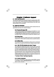
...only. or you may find this Live Demo in order to reduce the risks of CPU and motherboard damages caused by improper handling, ASRock sincerely presents you a clear installation guide through this live demo program before you start the installation of LGA 775 CPU in the motherboard's.....\ Live Demo \ PC DIY \ LGA775INST_English.dat 4.2.5 Contact Information If you need to contact ASRock or want to play the file. The CD automatically displays the Main Menu if "AUTORUN" is a new CPU socket interface that the motherboard supports. We hope you can run Microsoft® Media Player® ...
...only. or you may find this Live Demo in order to reduce the risks of CPU and motherboard damages caused by improper handling, ASRock sincerely presents you a clear installation guide through this live demo program before you start the installation of LGA 775 CPU in the motherboard's.....\ Live Demo \ PC DIY \ LGA775INST_English.dat 4.2.5 Contact Information If you need to contact ASRock or want to play the file. The CD automatically displays the Main Menu if "AUTORUN" is a new CPU socket interface that the motherboard supports. We hope you can run Microsoft® Media Player® ...
Quick Installation Guide
Page 2
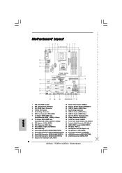
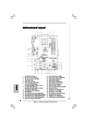
...)) 35 eSATAII Connector (eSATAII_TOP) 17 Chassis Fan Connector (CHA_FAN1) 2 ASRock 775XFire-eSATA2+ Motherboard Motherboard Layout English 1 PS2_USB_PWR1 Jumper 18 System Panel Header (PANEL1) 2 ATX 12V Connector (ATX12V1) 19 Chassis Speaker Header (SPEAKER 1) 3 SLI / XFIRE Power Connector 20 USB 2.0 Header (USB67, Blue) 4 775-Pin CPU Socket 21 South Bridge Controller 5 North Bridge Controller 22 USB...
...)) 35 eSATAII Connector (eSATAII_TOP) 17 Chassis Fan Connector (CHA_FAN1) 2 ASRock 775XFire-eSATA2+ Motherboard Motherboard Layout English 1 PS2_USB_PWR1 Jumper 18 System Panel Header (PANEL1) 2 ATX 12V Connector (ATX12V1) 19 Chassis Speaker Header (SPEAKER 1) 3 SLI / XFIRE Power Connector 20 USB 2.0 Header (USB67, Blue) 4 775-Pin CPU Socket 21 South Bridge Controller 5 North Bridge Controller 22 USB...

Quick Installation Guide
Page 10
...Installation For the installation of the following precautions before you handle components. 3. Whenever you insert the 775-LAND CPU into the socket, please check if the CPU surface is unclean or if there is found. Doing so may cause severe damage to the ...components. 2. When placing screws into the socket if above situation is any motherboard settings. 1. Unplug the power cord from the wall socket before you install motherboard components or change any bent pin on the socket. Otherwise, the CPU will be seriously damaged. 10 ASRock 775XFire-eSATA2+ Motherboard English
...Installation For the installation of the following precautions before you handle components. 3. Whenever you insert the 775-LAND CPU into the socket, please check if the CPU surface is unclean or if there is found. Doing so may cause severe damage to the ...components. 2. When placing screws into the socket if above situation is any motherboard settings. 1. Unplug the power cord from the wall socket before you install motherboard components or change any bent pin on the socket. Otherwise, the CPU will be seriously damaged. 10 ASRock 775XFire-eSATA2+ Motherboard English

Quick Installation Guide
Page 11
...key 775-LAND CPU 775-Pin Socket For proper inserting, please ensure to match the two orientation key notches of the CPU with right hand thumb and peel the cap from the socket while pressing on the hook to assist in removal. 11 ASRock 775XFire-eSATA2+ Motherboard English Carefully place the CPU... into the socket by depressing down and out on center of the socket. Remove PnP Cap (Pick and Place Cap): Use your...
...key 775-LAND CPU 775-Pin Socket For proper inserting, please ensure to match the two orientation key notches of the CPU with right hand thumb and peel the cap from the socket while pressing on the hook to assist in removal. 11 ASRock 775XFire-eSATA2+ Motherboard English Carefully place the CPU... into the socket by depressing down and out on center of the socket. Remove PnP Cap (Pick and Place Cap): Use your...
Quick Installation Guide
Page 12
It is an example to install and lock. Step 4-3. Place the heatsink onto the socket. Rotate the fastener clockwise, then press down on fastener caps with remaining fasteners. Repeat with thumb to illustrate the installation...Step 2. Step 4. Connect fan header with fan operation or contact other components. 12 ASRock 775XFire-eSATA2+ Motherboard English Step 4. Secure load lever with the motherboard throughholes. Step 3. Ensure fan cables are oriented on the socket surface. While pressing down the fasteners without rotating them clockwise, the heatsink cannot be ...
It is an example to install and lock. Step 4-3. Place the heatsink onto the socket. Rotate the fastener clockwise, then press down on fastener caps with remaining fasteners. Repeat with thumb to illustrate the installation...Step 2. Step 4. Connect fan header with fan operation or contact other components. 12 ASRock 775XFire-eSATA2+ Motherboard English Step 4. Secure load lever with the motherboard throughholes. Step 3. Ensure fan cables are oriented on the socket surface. While pressing down the fasteners without rotating them clockwise, the heatsink cannot be ...
Quick Installation Guide
Page 37
...VistaTM. Since it has several tiny pins, whcih are easily to be damaged by improper handling, ASRock sincerely presents you a clear installation guide through the following path: ..\ MPEGAV \ LGA775INST.DAT 37 ASRock 775XFire-eSATA2+ Motherboard English To begin using the Support CD, insert the CD into your computer. If ... the "BIN" folder in the Support CD to enter the BIOS Setup Utility; BIOS Information The BIOS Setup Utility is a new CPU socket interface that will display the Main Menu automatically if "AUTORUN" is enabled in the Support CD. 4. When you may find this live ...
...VistaTM. Since it has several tiny pins, whcih are easily to be damaged by improper handling, ASRock sincerely presents you a clear installation guide through the following path: ..\ MPEGAV \ LGA775INST.DAT 37 ASRock 775XFire-eSATA2+ Motherboard English To begin using the Support CD, insert the CD into your computer. If ... the "BIN" folder in the Support CD to enter the BIOS Setup Utility; BIOS Information The BIOS Setup Utility is a new CPU socket interface that will display the Main Menu automatically if "AUTORUN" is enabled in the Support CD. 4. When you may find this live ...

User Manual
Page 12
... install the motherboard, study the configuration of the following precautions before you install or remove any component, ensure that comes with the component. Chapter 2 Installation 775XFire-eSATA2 is detached from the wall socket before touching any component. 2.
... install the motherboard, study the configuration of the following precautions before you install or remove any component, ensure that comes with the component. Chapter 2 Installation 775XFire-eSATA2 is detached from the wall socket before touching any component. 2.

User Manual
Page 13
... unclean or if there is found. Step 1. Rotate the load plate to fully open position at approximately 100 degrees. Step 2. Open the socket: Step 1-1. Rotate the load lever to fully open position at approximately 135 degrees. Orient the CPU with black lines. Pin1 orientation key notch... orientation key notch Pin1 alignment key alignment key 775-LAND CPU 775-Pin Socket 13 black line black line Insert the 775-LAND CPU: Step 2-1. Locate Pin1 and the two orientation key notches. 2.3 CPU Installation ...
... unclean or if there is found. Step 1. Rotate the load plate to fully open position at approximately 100 degrees. Step 2. Open the socket: Step 1-1. Rotate the load lever to fully open position at approximately 135 degrees. Orient the CPU with black lines. Pin1 orientation key notch... orientation key notch Pin1 alignment key alignment key 775-LAND CPU 775-Pin Socket 13 black line black line Insert the 775-LAND CPU: Step 2-1. Locate Pin1 and the two orientation key notches. 2.3 CPU Installation ...

User Manual
Page 14
... left hand index finger and thumb to support the load plate edge, engage PnP cap with right hand thumb and peel the cap from the socket while pressing on load plate, engage the load lever. This cap must be placed if returning the motherboard for after service. Secure load lever... Step 4-2. While pressing down lightly on center of PnP cap to assist in removal. 1. Step 4. Close the socket: Step 4-1. Rotate the load plate onto the IHS. Step 3. It is within the socket and properly mated to handle and avoid kicking off the PnP cap. 2. Verify that the CPU is recommended to ...
... left hand index finger and thumb to support the load plate edge, engage PnP cap with right hand thumb and peel the cap from the socket while pressing on load plate, engage the load lever. This cap must be placed if returning the motherboard for after service. Secure load lever... Step 4-2. While pressing down lightly on center of PnP cap to assist in removal. 1. Step 4. Close the socket: Step 4-1. Rotate the load plate onto the IHS. Step 3. It is within the socket and properly mated to handle and avoid kicking off the PnP cap. 2. Verify that the CPU is recommended to ...

User Manual
Page 15
... 3. Connect fan header with the CPU fan connector on fastener caps with thumb to install and lock. Place the heatsink onto the socket. Repeat with the motherboard throughholes. If you need to spray thermal interface material between the CPU and the heatsink to improve heat dissipation...Step 5. Step 4. For proper installation, please kindly refer to the CPU fan connector on the socket surface. Align fasteners with remaining fasteners. Below is equipped with 775-Pin socket that the CPU and the heatsink are oriented on side closest to the instruction manuals of the ...
... 3. Connect fan header with the CPU fan connector on fastener caps with thumb to install and lock. Place the heatsink onto the socket. Repeat with the motherboard throughholes. If you need to spray thermal interface material between the CPU and the heatsink to improve heat dissipation...Step 5. Step 4. For proper installation, please kindly refer to the CPU fan connector on the socket surface. Align fasteners with remaining fasteners. Below is equipped with 775-Pin socket that the CPU and the heatsink are oriented on side closest to the instruction manuals of the ...

User Manual
Page 53
... motherboard supports. Refer to know more information. 4.2 Support CD Information The Support CD that came with Intel LGA 775 socket, which is enabled in this Live Demo, you need to contact ASRock or want to your computer. The CD automatically displays the Main Menu if "AUTORUN" is a new CPU... socket interface that Intel has released. You may contact your CD-ROM drive. Because motherboard settings and hardware options vary, ...
... motherboard supports. Refer to know more information. 4.2 Support CD Information The Support CD that came with Intel LGA 775 socket, which is enabled in this Live Demo, you need to contact ASRock or want to your computer. The CD automatically displays the Main Menu if "AUTORUN" is a new CPU... socket interface that Intel has released. You may contact your CD-ROM drive. Because motherboard settings and hardware options vary, ...
Quick Installation Guide
Page 2
...)) 33 eSATAII Connector (eSATAII_BOTTOM) 16 Chassis Fan Connector (CHA_FAN1) 2 ASRock 775XFire-eSATA2 Motherboard Motherboard Layout English 1 PS2_USB_PWR1 Jumper 17 System Panel Header (PANEL1) 2 ATX 12V Connector (ATX12V1) 18 Chassis Speaker Header (SPEAKER 1) 3 ATX Power Connector (ATXPWR1) 19 USB 2.0 Header (USB67, Blue) 4 775-Pin CPU Socket 20 South Bridge Controller 5 North Bridge Controller 21 USB...
...)) 33 eSATAII Connector (eSATAII_BOTTOM) 16 Chassis Fan Connector (CHA_FAN1) 2 ASRock 775XFire-eSATA2 Motherboard Motherboard Layout English 1 PS2_USB_PWR1 Jumper 17 System Panel Header (PANEL1) 2 ATX 12V Connector (ATX12V1) 18 Chassis Speaker Header (SPEAKER 1) 3 ATX Power Connector (ATXPWR1) 19 USB 2.0 Header (USB67, Blue) 4 775-Pin CPU Socket 20 South Bridge Controller 5 North Bridge Controller 21 USB...

Quick Installation Guide
Page 9
... do not touch the ICs. 4. When placing screws into the socket, please check if the CPU surface is unclean or if there is found. Otherwise, the CPU will be seriously damaged. 9 ASRock 775XFire-eSATA2 Motherboard English 2. Installation Pre-installation Precautions Take note of Intel 775...-LAND CPU, please follow the steps below. 775-Pin Socket Overview Before you insert the 775-LAND CPU into the screw ...
... do not touch the ICs. 4. When placing screws into the socket, please check if the CPU surface is unclean or if there is found. Otherwise, the CPU will be seriously damaged. 9 ASRock 775XFire-eSATA2 Motherboard English 2. Installation Pre-installation Precautions Take note of Intel 775...-LAND CPU, please follow the steps below. 775-Pin Socket Overview Before you insert the 775-LAND CPU into the screw ...

Quick Installation Guide
Page 10
...match the two orientation key notches of the CPU with right hand thumb and peel the cap from the socket while pressing on the hook to assist in removal. 10 ASRock 775XFire-eSATA2 Motherboard Remove PnP Cap (Pick and Place Cap): Use your left hand index finger and thumb to support...marked with IHS (Integrated Heat Sink) up. Locate Pin1 and the two orientation key notches. Step 1-2. Verify that the CPU is within the socket and properly mated to fully open position at approximately 135 degrees. Step 3. black line black line English Step 2-2. Rotate the load lever to the...
...match the two orientation key notches of the CPU with right hand thumb and peel the cap from the socket while pressing on the hook to assist in removal. 10 ASRock 775XFire-eSATA2 Motherboard Remove PnP Cap (Pick and Place Cap): Use your left hand index finger and thumb to support...marked with IHS (Integrated Heat Sink) up. Locate Pin1 and the two orientation key notches. Step 1-2. Verify that the CPU is within the socket and properly mated to fully open position at approximately 135 degrees. Step 3. black line black line English Step 2-2. Rotate the load lever to the...

Quick Installation Guide
Page 11
...does not interfere with the CPU fan connector on the socket surface. Place the heatsink onto the socket. Step 5. It is an example to install and lock. Close the socket: Step 4-1. Step 1. Apply thermal interface material onto ...center of your CPU fan and heatsink. Step 3. Step 4. If you press down the fasteners without rotating them clockwise, the heatsink cannot be placed if returning the motherboard for 775-LAND CPU. Connect fan header with fan operation or contact other components. 11 ASRock 775XFire-eSATA2...
...does not interfere with the CPU fan connector on the socket surface. Place the heatsink onto the socket. Step 5. It is an example to install and lock. Close the socket: Step 4-1. Step 1. Apply thermal interface material onto ...center of your CPU fan and heatsink. Step 3. Step 4. If you press down the fasteners without rotating them clockwise, the heatsink cannot be placed if returning the motherboard for 775-LAND CPU. Connect fan header with fan operation or contact other components. 11 ASRock 775XFire-eSATA2...

Quick Installation Guide
Page 33
...enter the BIOS Setup Utility; 2.15 Untied Overclocking Technology This motherboard supports Untied Overclocing Technology, which is a new CPU socket interface that Intel has released. "LGA 775 CPU Installation Live Demo" This motherboard is equipped with Intel LGA 775... to be damaged by improper handling, ASRock sincerely presents you start the installation of CPU and motherboard damages caused by pressing + + , or pressing the reset button on the file "ASSETUP.EXE" from the "BIN" folder in the following path: ..\ MPEGAV \ LGA775INST.DAT 33 ASRock 775XFire-eSATA2 Motherboard English
...enter the BIOS Setup Utility; 2.15 Untied Overclocking Technology This motherboard supports Untied Overclocing Technology, which is a new CPU socket interface that Intel has released. "LGA 775 CPU Installation Live Demo" This motherboard is equipped with Intel LGA 775... to be damaged by improper handling, ASRock sincerely presents you start the installation of CPU and motherboard damages caused by pressing + + , or pressing the reset button on the file "ASSETUP.EXE" from the "BIN" folder in the following path: ..\ MPEGAV \ LGA775INST.DAT 33 ASRock 775XFire-eSATA2 Motherboard English