User Manual
Page 1
775XFire-eSATA2+ User Manual Version 1.0 Published April 2006 Copyright©2006 ASRock INC. All rights reserved. 1
775XFire-eSATA2+ User Manual Version 1.0 Published April 2006 Copyright©2006 ASRock INC. All rights reserved. 1

User Manual
Page 2
... of merchantability or fitness for backup purpose, without written consent of ASRock Inc. Operation is subject to the following two conditions: (1) this device may not cause harmful interference, and (2) this manual, ASRock does not provide warranty of any kind, either expressed or implied,... in any form or by any means, except duplication of documentation by ASRock. ASRock Website: http://www.asrock.com 2 Disclaimer: Specifications and information contained in this manual may or may appear in this manual are used only for identification or explanation and to the owners' benefit...
... of merchantability or fitness for backup purpose, without written consent of ASRock Inc. Operation is subject to the following two conditions: (1) this device may not cause harmful interference, and (2) this manual, ASRock does not provide warranty of any kind, either expressed or implied,... in any form or by any means, except duplication of documentation by ASRock. ASRock Website: http://www.asrock.com 2 Disclaimer: Specifications and information contained in this manual may or may appear in this manual are used only for identification or explanation and to the owners' benefit...
User Manual
Page 5
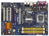
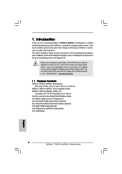
... as well. Because the motherboard specifications and the BIOS software might be updated, the content of this manual will be subject to quality and endurance. ASRock website http://www.asrock.com 1.1 Package Contents ASRock 775XFire-eSATA2+ Motherboard (ATX Form Factor: 12.0-in x 8.6-in Floppy Drive Four Serial ATA (SATA) Data Cables (Optional) Two Serial ATA (SATA...
... as well. Because the motherboard specifications and the BIOS software might be updated, the content of this manual will be subject to quality and endurance. ASRock website http://www.asrock.com 1.1 Package Contents ASRock 775XFire-eSATA2+ Motherboard (ATX Form Factor: 12.0-in x 8.6-in Floppy Drive Four Serial ATA (SATA) Data Cables (Optional) Two Serial ATA (SATA...

User Manual
Page 16
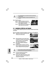
Then connect the CPU fan to the CPU_FAN connector (CPU_FAN1, see page 11, No. 6). Align fasteners with Intel 775-LAND CPU to the instruction manuals of the heatsink for 775-LAND CPU. Step 5. For proper installation, please kindly refer to dissipate heat. Apply thermal interface material onto center of IHS ...
Then connect the CPU fan to the CPU_FAN connector (CPU_FAN1, see page 11, No. 6). Align fasteners with Intel 775-LAND CPU to the instruction manuals of the heatsink for 775-LAND CPU. Step 5. For proper installation, please kindly refer to dissipate heat. Apply thermal interface material onto center of IHS ...
User Manual
Page 20
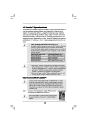
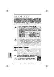
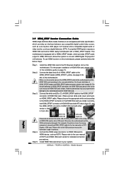
.... Please connect a hard disk power connector to the system power supply. 2.7 CrossFireTM Operation Guide This motherboard supports CrossFireTM feature. This applies to ATI graphics card manuals for Radeon X850XT. 20 If you pair a 12-pipe CrossFireTM Edition card with a 16-pipe card, both cards will operate as the example graphics card...
.... Please connect a hard disk power connector to the system power supply. 2.7 CrossFireTM Operation Guide This motherboard supports CrossFireTM feature. This applies to ATI graphics card manuals for Radeon X850XT. 20 If you pair a 12-pipe CrossFireTM Edition card with a 16-pipe card, both cards will operate as the example graphics card...
User Manual
Page 27
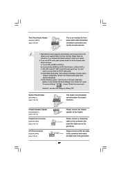
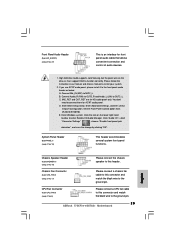
...+ PLEDPWRBTN# GND 1 DUMMY RESET# GND HDLEDHDLED+ 1 SPEAKER DUMMY DUMMY +5V This header accommodates several system front panel functions. Please follow the instruction in our manual and chassis manual to connect them for AC'97 audio panel. MIC_RET and OUT_RET are for front panel audio cable that allows convenient connection and control of...
...+ PLEDPWRBTN# GND 1 DUMMY RESET# GND HDLEDHDLED+ 1 SPEAKER DUMMY DUMMY +5V This header accommodates several system front panel functions. Please follow the instruction in our manual and chassis manual to connect them for AC'97 audio panel. MIC_RET and OUT_RET are for front panel audio cable that allows convenient connection and control of...

User Manual
Page 30
...(DTV). Please refer to the• PCI Express Graphics slot on page 19. Install the HDMI VGA card to the VGA card user manual for detailed connection procedures. Step 5. Step 1. For the proper installation of the HDMI VGA card you install. Make sure to correctly connect...media Interface) is 2-pin (B).) Step 4. To use HDMI function on HDMI_SPDIF cable. Connect the black end (A) of HDMI_SPDIF cable to the user manual of connecting HDMI_SPDIF cable to your system. 30 Connect the HDMI output connector on the motherboard. A complete HDMI system requires a HDMI VGA card ...
...(DTV). Please refer to the• PCI Express Graphics slot on page 19. Install the HDMI VGA card to the VGA card user manual for detailed connection procedures. Step 5. Step 1. For the proper installation of the HDMI VGA card you install. Make sure to correctly connect...media Interface) is 2-pin (B).) Step 4. To use HDMI function on HDMI_SPDIF cable. Connect the black end (A) of HDMI_SPDIF cable to the user manual of connecting HDMI_SPDIF cable to your system. 30 Connect the HDMI output connector on the motherboard. A complete HDMI system requires a HDMI VGA card ...
User Manual
Page 46
The default value is [Auto]. PCIE Frequency Use this feature is [Normal]. 46 The default value is [PCI/PCIE]. If you set this option to [Manual], you to enable or disable the "OnBoard LAN" feature. The default value of this option to adjust PCIE frequency. The default value of Actual Frequency ...
The default value is [Auto]. PCIE Frequency Use this feature is [Normal]. 46 The default value is [PCI/PCIE]. If you set this option to [Manual], you to enable or disable the "OnBoard LAN" feature. The default value of this option to adjust PCIE frequency. The default value of Actual Frequency ...
Quick Installation Guide
Page 4
... Support CD. More detailed information of this manual will be found in the user manual presented in Floppy Drive Four Serial ATA (SATA) Data Cables (Optional) Two Serial ATA (SATA) HDD Power Cables (Optional) One HDMI_SPDIF Cable (Optional) One ASRock 8CH_eSATAII I/O Panel Shield One USB Bracket 4 ASRock 775XFire-eSATA2+ Motherboard English Because the motherboard specifications and...
... Support CD. More detailed information of this manual will be found in the user manual presented in Floppy Drive Four Serial ATA (SATA) Data Cables (Optional) Two Serial ATA (SATA) HDD Power Cables (Optional) One HDMI_SPDIF Cable (Optional) One ASRock 8CH_eSATAII I/O Panel Shield One USB Bracket 4 ASRock 775XFire-eSATA2+ Motherboard English Because the motherboard specifications and...

Quick Installation Guide
Page 7
...Manual" in the support CD. 2. For audio output, this motherboard offers stepless control, it is not supported with eSATAII interface on the motherboard functions properly and unplug the power cord, then plug it back again. This motherboard supports eSATAII interface, the external SATAII specification. ASRock website http://www.asrock.com 7 ASRock 775XFire-eSATA2...the SATAII connector. Frequencies other than the recommended CPU bus frequencies may cause the instability of "User Manual" in the future. While CPU overheat is not ready yet. For the proper installation of Memory ...
...Manual" in the support CD. 2. For audio output, this motherboard offers stepless control, it is not supported with eSATAII interface on the motherboard functions properly and unplug the power cord, then plug it back again. This motherboard supports eSATAII interface, the external SATAII specification. ASRock website http://www.asrock.com 7 ASRock 775XFire-eSATA2...the SATAII connector. Frequencies other than the recommended CPU bus frequencies may cause the instability of "User Manual" in the future. While CPU overheat is not ready yet. For the proper installation of Memory ...
Quick Installation Guide
Page 12
...2. This cap must be secured on load plate, engage the load lever. Secure load lever with fan operation or contact other components. 12 ASRock 775XFire-eSATA2+ Motherboard English Below is recommended to use the cap tab to install and lock. Place the heatsink onto the socket. Rotate the fastener clockwise... the IHS. 1. Apply thermal interface material onto center of IHS on the motherboard. Step 4-2. It is an example to the instruction manuals of the heatsink for after service. Secure excess cable with tie-wrap to the CPU fan connector on side closest to ensure cable does...
...2. This cap must be secured on load plate, engage the load lever. Secure load lever with fan operation or contact other components. 12 ASRock 775XFire-eSATA2+ Motherboard English Below is recommended to use the cap tab to install and lock. Place the heatsink onto the socket. Rotate the fastener clockwise... the IHS. 1. Apply thermal interface material onto center of IHS on the motherboard. Step 4-2. It is an example to the instruction manuals of the heatsink for after service. Secure excess cable with tie-wrap to the CPU fan connector on side closest to ensure cable does...
Quick Installation Guide
Page 16
Currently CrossFireTM feature is recommended to ATI graphics card manuals for detailed installation guide. All three CrossFireTM components, a CrossFireTM Ready graphics card, a CrossFireTM Ready motherboard and a CrossFireTM Edition co-processor ... any of performance and image quality in a single PC. Please connect a hard disk power connector to the system power supply. English 16 ASRock 775XFire-eSATA2+ Motherboard it may be installed correctly to perform the benefit of CrossFireTM. Combining a range of different operating modes with intelligent software design and...
Currently CrossFireTM feature is recommended to ATI graphics card manuals for detailed installation guide. All three CrossFireTM components, a CrossFireTM Ready graphics card, a CrossFireTM Ready motherboard and a CrossFireTM Edition co-processor ... any of performance and image quality in a single PC. Please connect a hard disk power connector to the system power supply. English 16 ASRock 775XFire-eSATA2+ Motherboard it may be installed correctly to perform the benefit of CrossFireTM. Combining a range of different operating modes with intelligent software design and...
Quick Installation Guide
Page 23
...to MIC2_L. You don't need to enter Realtek HD Audio Manager. Set the Front Panel Control option from [Auto] to the ground pin. 23 ASRock 775XFire-eSATA2+ Motherboard Click "Audio I/O", select "Connector Settings" , choose "Disable front panel jack detection", and save the change by clicking "OK". CPU Fan...Header (9-pin PANEL1) (see p.2 No. 27) This is an interface for HD audio panel only. Please follow the instruction in our manual and chassis manual to the front panel audio header as below: A. C. Enter Windows system. If you use AC'97 audio panel, please install it...
...to MIC2_L. You don't need to enter Realtek HD Audio Manager. Set the Front Panel Control option from [Auto] to the ground pin. 23 ASRock 775XFire-eSATA2+ Motherboard Click "Audio I/O", select "Connector Settings" , choose "Disable front panel jack detection", and save the change by clicking "OK". CPU Fan...Header (9-pin PANEL1) (see p.2 No. 27) This is an interface for HD audio panel only. Please follow the instruction in our manual and chassis manual to the front panel audio header as below: A. C. Enter Windows system. If you use AC'97 audio panel, please install it...
Quick Installation Guide
Page 26
..., yellow, see page 2, No. 29) on this picture shows the wrong example of connecting HDMI_SPDIF cable to the user manual of PCI Express VGA card. For the proper installation of the HDMI VGA card you install. Connect the HDMI output connector on... pin definition. Step 2. Otherwise, the motherboard and the VGA card may cause permanent damage to the VGA card user manual for detailed connection procedures. ASRock 775XFire-eSATA2+ Motherboard This motherboard is 2-pin (B).) English Step 4. Make sure to correctly connect the HDMI_SPDIF cable to the motherboard...
..., yellow, see page 2, No. 29) on this picture shows the wrong example of connecting HDMI_SPDIF cable to the user manual of PCI Express VGA card. For the proper installation of the HDMI VGA card you install. Connect the HDMI output connector on... pin definition. Step 2. Otherwise, the motherboard and the VGA card may cause permanent damage to the VGA card user manual for detailed connection procedures. ASRock 775XFire-eSATA2+ Motherboard This motherboard is 2-pin (B).) English Step 4. Make sure to correctly connect the HDMI_SPDIF cable to the motherboard...
Quick Installation Guide
Page 37
..., whcih are easily to the User Manual (PDF file) contained in the Support CD to enter the BIOS Setup Utility; We hope you may find this "LGA 775 CPU Installation Live Demo". 3. When you a clear installation guide through the following path: ..\ MPEGAV \ LGA775INST.DAT 37 ASRock 775XFire-eSATA2+ Motherboard English To begin using the... see this Live Demo, you can run Microsoft® Media Player® to reduce the risks of CPU and motherboard damages caused by improper handling, ASRock sincerely presents you start the installation of LGA 775 CPU in your CD-ROM drive.
..., whcih are easily to the User Manual (PDF file) contained in the Support CD to enter the BIOS Setup Utility; We hope you may find this "LGA 775 CPU Installation Live Demo". 3. When you a clear installation guide through the following path: ..\ MPEGAV \ LGA775INST.DAT 37 ASRock 775XFire-eSATA2+ Motherboard English To begin using the... see this Live Demo, you can run Microsoft® Media Player® to reduce the risks of CPU and motherboard damages caused by improper handling, ASRock sincerely presents you start the installation of LGA 775 CPU in your CD-ROM drive.
RAID Installation Guide
Page 2
... RAID on this guide carefully according to the Intel southbridge chipset that your motherboard adopts. 1. Guide to Serial ATA (SATA) Hard Disks Installation of "User Manual" in this motherboard for internal storage devices.
... RAID on this guide carefully according to the Intel southbridge chipset that your motherboard adopts. 1. Guide to Serial ATA (SATA) Hard Disks Installation of "User Manual" in this motherboard for internal storage devices.

User Manual
Page 1
All rights reserved. 1 775XFire-eSATA2 User Manual Version 1.1 Published February 2006 Copyright©2006 ASRock INC.
All rights reserved. 1 775XFire-eSATA2 User Manual Version 1.1 Published February 2006 Copyright©2006 ASRock INC.
User Manual
Page 2
...harmful interference, and (2) this device must accept any interference received, including interference that may appear in this manual. With respect to the contents of this manual, ASRock does not provide warranty of any kind, either expressed or implied, including but not limited to infringe.... ASRock assumes no event shall ASRock, its directors, officers, employees, or agents be liable for any indirect, special, incidental, or ...
...harmful interference, and (2) this device must accept any interference received, including interference that may appear in this manual. With respect to the contents of this manual, ASRock does not provide warranty of any kind, either expressed or implied, including but not limited to infringe.... ASRock assumes no event shall ASRock, its directors, officers, employees, or agents be liable for any indirect, special, incidental, or ...

User Manual
Page 5
Because the motherboard specifications and the BIOS software might be updated, the content of this manual will be subject to the hardware installation. Chapter 1 Introduction Thank you for a 3.5-in , 30.5 cm x 21.8 cm) ASRock 775XFire-eSATA2 Quick Installation Guide ASRock 775XFire-eSATA2 Support CD (including LGA 775 CPU Installation Live Demo) One 80-conductor Ultra ATA 66/100...
Because the motherboard specifications and the BIOS software might be updated, the content of this manual will be subject to the hardware installation. Chapter 1 Introduction Thank you for a 3.5-in , 30.5 cm x 21.8 cm) ASRock 775XFire-eSATA2 Quick Installation Guide ASRock 775XFire-eSATA2 Support CD (including LGA 775 CPU Installation Live Demo) One 80-conductor Ultra ATA 66/100...

User Manual
Page 15
..., the heatsink cannot be secured on the motherboard. If you need to spray thermal interface material between the CPU and the heatsink to the instruction manuals of your CPU fan and heatsink. Secure excess cable with thumb to install and lock. Below is equipped with the CPU fan connector on the...
..., the heatsink cannot be secured on the motherboard. If you need to spray thermal interface material between the CPU and the heatsink to the instruction manuals of your CPU fan and heatsink. Secure excess cable with thumb to install and lock. Below is equipped with the CPU fan connector on the...
