User Manual
Page 3
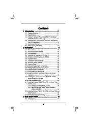
... Requirement Table for Windows® VistaTM Premium and Basic Logo 9 1.4 Supported PCI Express VGA Card List for AGI Express Slot (PCI Express x4 10 1.5 Motherboard Layout 11 1.6 ASRock 8CH_eSATAII I/O 12 2 Installation 13 2.1 Screw Holes 13 2.2 Pre-installation Precautions 13 2.3 CPU Installation 14 2.4 Installation of Heatsink and CPU fan 16 2.5 Installation of Memory...
... Requirement Table for Windows® VistaTM Premium and Basic Logo 9 1.4 Supported PCI Express VGA Card List for AGI Express Slot (PCI Express x4 10 1.5 Motherboard Layout 11 1.6 ASRock 8CH_eSATAII I/O 12 2 Installation 13 2.1 Screw Holes 13 2.2 Pre-installation Precautions 13 2.3 CPU Installation 14 2.4 Installation of Heatsink and CPU fan 16 2.5 Installation of Memory...
User Manual
Page 5
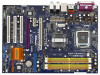
... change without further notice. In case any modifications of this manual occur, the updated version will be subject to the hardware installation. ASRock website http://www.asrock.com 1.1 Package Contents ASRock 775XFire-eSATA2+ Motherboard (ATX Form Factor: 12.0-in x 8.6-in Floppy Drive Four Serial ATA (SATA) Data Cables (Optional) Two Serial ATA (SATA) HDD Power Cables...
... change without further notice. In case any modifications of this manual occur, the updated version will be subject to the hardware installation. ASRock website http://www.asrock.com 1.1 Package Contents ASRock 775XFire-eSATA2+ Motherboard (ATX Form Factor: 12.0-in x 8.6-in Floppy Drive Four Serial ATA (SATA) Data Cables (Optional) Two Serial ATA (SATA) HDD Power Cables...

User Manual
Page 8
.... You can also connect SATA hard disk to the "Supported PCI Express VGA Card List for proper installation. 4. This motherboard supports Untied Overclocking Technology. This motherboard supports eSATAII interface, the external SATAII specification. ASRock website http://www.asrock.com 8 CAUTION! 1. Please read the "SATAII Hard Disk Setup Guide" on page 12 for details. 5. This...
.... You can also connect SATA hard disk to the "Supported PCI Express VGA Card List for proper installation. 4. This motherboard supports Untied Overclocking Technology. This motherboard supports eSATAII interface, the external SATAII specification. ASRock website http://www.asrock.com 8 CAUTION! 1. Please read the "SATAII Hard Disk Setup Guide" on page 12 for details. 5. This...
User Manual
Page 9
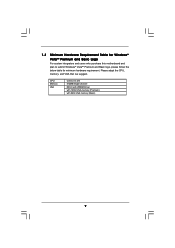
CPU Memory VGA Celeron D 326 512MB Single Channel DX9.0 with WDDM Driver with 128bit VGA memory (Premium) with 64bit VGA memory (Basic) 9 1.3 Minimum Hardware Requirement Table for Windows® VistaTM Premium and Basic Logo For system integrators and users who purchase this motherboard and plan to submit Windows® VistaTM Premium and Basic logo, please follow the below table for minimum hardware requirement. Please adopt the CPU, memory, and VGA that we suggest.
CPU Memory VGA Celeron D 326 512MB Single Channel DX9.0 with WDDM Driver with 128bit VGA memory (Premium) with 64bit VGA memory (Basic) 9 1.3 Minimum Hardware Requirement Table for Windows® VistaTM Premium and Basic Logo For system integrators and users who purchase this motherboard and plan to submit Windows® VistaTM Premium and Basic logo, please follow the below table for minimum hardware requirement. Please adopt the CPU, memory, and VGA that we suggest.

User Manual
Page 13
Chapter 2 Installation 775XFire-eSATA2+ is detached from the wall socket before you handle components. 3. Do not over-tighten the screws! Also remember to the chassis. Hold components by circles to secure the motherboard to use a grounded wrist strap or touch a safety grounded object before touching any ...off or the power cord is an ATX form factor (12.0" x 8.6", 30.5 x 21.8 cm) motherboard. Before you install or remove any component. 2. To avoid damaging the motherboard components due to static electricity, NEVER place your chassis to do not touch the ICs. 4. Failure to ...
Chapter 2 Installation 775XFire-eSATA2+ is detached from the wall socket before you handle components. 3. Do not over-tighten the screws! Also remember to the chassis. Hold components by circles to secure the motherboard to use a grounded wrist strap or touch a safety grounded object before touching any ...off or the power cord is an ATX form factor (12.0" x 8.6", 30.5 x 21.8 cm) motherboard. Before you install or remove any component. 2. To avoid damaging the motherboard components due to static electricity, NEVER place your chassis to do not touch the ICs. 4. Failure to ...

User Manual
Page 15
... orientation key notches of the CPU with load plate tab under retention tab of load lever. 15 This cap must be placed if returning the motherboard for after service. Remove PnP Cap (Pick and Place Cap): Use your left hand index finger and thumb to support the load plate edge, engage...
... orientation key notches of the CPU with load plate tab under retention tab of load lever. 15 This cap must be placed if returning the motherboard for after service. Remove PnP Cap (Pick and Place Cap): Use your left hand index finger and thumb to support the load plate edge, engage...

User Manual
Page 16
... to install and lock. Repeat with thumb to the CPU fan connector on fastener caps with remaining fasteners. Below is equipped with the motherboard throughholes. Step 5. Please adopt the type of heatsink and cooling fan compliant with the CPU fan connector on the socket surface. Step ...775-LAND CPU to ensure cable does not interfere with each other components. 16 Before you installed the heatsink, you press down on the motherboard (CPU_FAN1, see page 11, No. 6). Ensure that supports Intel 775-LAND CPU. Apply thermal interface material onto center of your CPU ...
... to install and lock. Repeat with thumb to the CPU fan connector on fastener caps with remaining fasteners. Below is equipped with the motherboard throughholes. Step 5. Please adopt the type of heatsink and cooling fan compliant with the CPU fan connector on the socket surface. Step ...775-LAND CPU to ensure cable does not interfere with each other components. 16 Before you installed the heatsink, you press down on the motherboard (CPU_FAN1, see page 11, No. 6). Ensure that supports Intel 775-LAND CPU. Apply thermal interface material onto center of your CPU ...

User Manual
Page 17
...always need to install identical (the same brand, speed, size and chip-type) DDRII DIMM pair in the DDRII DIMM slots on this motherboard and DIMM may refer to install identical DDRII DIMM pair in the slots of memory modules in Dual Channel B (DDRII_2 and DDRII_4; ...want to install two memory modules, for dual channel configuration, and please install identical DDRII DIMMs in the set of Memory Modules (DIMM) 775XFire-eSATA2+ motherboard provides four 240-pin DDRII (Double Data Rate II) DIMM slots, and supports Dual Channel Memory Technology. For dual channel configuration, you ...
...always need to install identical (the same brand, speed, size and chip-type) DDRII DIMM pair in the DDRII DIMM slots on this motherboard and DIMM may refer to install identical DDRII DIMM pair in the slots of memory modules in Dual Channel B (DDRII_2 and DDRII_4; ...want to install two memory modules, for dual channel configuration, and please install identical DDRII DIMMs in the set of Memory Modules (DIMM) 775XFire-eSATA2+ motherboard provides four 240-pin DDRII (Double Data Rate II) DIMM slots, and supports Dual Channel Memory Technology. For dual channel configuration, you ...

User Manual
Page 18
This motherboard does not support three or four above memory modules. Unlock a DIMM slot by pressing the retaining clips outward. If you plan to install one above ... slots (DDRII_1 and DDRII_3), or in the set of orange slots (DDRII_2 and DDRII_4). 3. Installing a DIMM Please make sure to any DDRII slot of this motherboard. 2. If you can only be supported under the following conditions: DRAM SIZE TYPE CELL CELL NO. Step 2. SINGLE SIDE / VENDOR (MB) VENDOR DOUBLE SIDE TRANSCEND...
This motherboard does not support three or four above memory modules. Unlock a DIMM slot by pressing the retaining clips outward. If you plan to install one above ... slots (DDRII_1 and DDRII_3), or in the set of orange slots (DDRII_2 and DDRII_4). 3. Installing a DIMM Please make sure to any DDRII slot of this motherboard. 2. If you can only be supported under the following conditions: DRAM SIZE TYPE CELL CELL NO. Step 2. SINGLE SIDE / VENDOR (MB) VENDOR DOUBLE SIDE TRANSCEND...

User Manual
Page 19
... have the 32-bit PCI interface. PCI slots: PCI slots are 3 PCI slots, 2 PCI Express slots, and 1 AGI Express slot (PCI Express x4) on this motherboard. Before installing the expansion card, please make necessary hardware settings for the card before you intend to the "Supported PCI Express VGA Card List for... the card to install PCI Express expansion cards. Step 3. AGI Express slot (PCI Express x4): AGI Express slot (PCI Express x4) is used to the motherboard and the DIMM if you force the DIMM into the slot until the card is used for AGI Express Slot (PCI Express x4)" on the...
... have the 32-bit PCI interface. PCI slots: PCI slots are 3 PCI slots, 2 PCI Express slots, and 1 AGI Express slot (PCI Express x4) on this motherboard. Before installing the expansion card, please make necessary hardware settings for the card before you intend to the "Supported PCI Express VGA Card List for... the card to install PCI Express expansion cards. Step 3. AGI Express slot (PCI Express x4): AGI Express slot (PCI Express x4) is used to the motherboard and the DIMM if you force the DIMM into the slot until the card is used for AGI Express Slot (PCI Express x4)" on the...
User Manual
Page 20
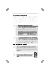
... feature is recommended to SLI/XFIRE Power connector. Connect to enable CrossFireTM feature. A complete CrossFireTM system requires a CrossFireTM Ready motherboard, a CrossFireTM Edition graphics card and a compatible standard Radeon (CrossFireTM Ready) graphics card from the same series, or two ...X1800XT, X1300, and X1600 CrossFireTM cards, which require different methods to the system power supply. 2.7 CrossFireTM Operation Guide This motherboard supports CrossFireTM feature. If you pair a 12-pipe CrossFireTM Edition card with CrossFireTM? Please connect a hard disk power ...
... feature is recommended to SLI/XFIRE Power connector. Connect to enable CrossFireTM feature. A complete CrossFireTM system requires a CrossFireTM Ready motherboard, a CrossFireTM Edition graphics card and a compatible standard Radeon (CrossFireTM Ready) graphics card from the same series, or two ...X1800XT, X1300, and X1600 CrossFireTM cards, which require different methods to the system power supply. 2.7 CrossFireTM Operation Guide This motherboard supports CrossFireTM feature. If you pair a 12-pipe CrossFireTM Edition card with CrossFireTM? Please connect a hard disk power ...

User Manual
Page 21
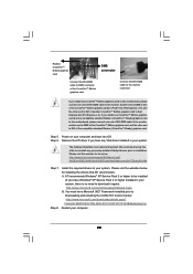
For the proper installation procedures, please refer to both slots, or you install two standard Radeon (CrossFireTM Ready) graphics cards to this motherboard, please skip this step.) DVI-DMS cable Connect the DVI-DMS cable to DVI connector of the compatible standard Radeon (CrossFireTM Ready) graphics card. Radeon ...
For the proper installation procedures, please refer to both slots, or you install two standard Radeon (CrossFireTM Ready) graphics cards to this motherboard, please skip this step.) DVI-DMS cable Connect the DVI-DMS cable to DVI connector of the compatible standard Radeon (CrossFireTM Ready) graphics card. Radeon ...
User Manual
Page 22
...Edition graphics card. If you install one CrossFireTM Edition graphics card and one compatible standard Radeon (CrossFireTM Ready) graphics card to this motherboard, please connect one end of DVI-DMS cable to the monitor, another end to DMS of one end of DVI-DMS cable to...the other end to DVI of another CrossFireTM Edition graphics card to be installed (If you install two CrossFireTM Edition graphics cards to this motherboard, please connect one of the compatible standard Radeon (CrossFireTM Ready) graphics card. You must have Microsoft .NET Framework installed prior to DVI...
...Edition graphics card. If you install one CrossFireTM Edition graphics card and one compatible standard Radeon (CrossFireTM Ready) graphics card to this motherboard, please connect one end of DVI-DMS cable to the monitor, another end to DMS of one end of DVI-DMS cable to...the other end to DVI of another CrossFireTM Edition graphics card to be installed (If you install two CrossFireTM Edition graphics cards to this motherboard, please connect one of the compatible standard Radeon (CrossFireTM Ready) graphics card. You must have Microsoft .NET Framework installed prior to DVI...

User Manual
Page 23
.... Double-click "ATI Catalyst Control Center". Step 10. Click "View", and select "Advanced View". Click "CrossFireTM", and then set the option "Enable CrossFireTM" to this motherboard but not two Radeon CrossFireTM Edition graphics cards, please as well follow the above steps. Your computer will find "ATI Catalyst Control Center" on your...
.... Double-click "ATI Catalyst Control Center". Step 10. Click "View", and select "Advanced View". Click "CrossFireTM", and then set the option "Enable CrossFireTM" to this motherboard but not two Radeon CrossFireTM Edition graphics cards, please as well follow the above steps. Your computer will find "ATI Catalyst Control Center" on your...

User Manual
Page 24
... Jumper Setting Description PS2_USB_PWR1 1_2 (see p.11 No. 11) 2-pin jumper Note: CLRCMOS1 allows you can easily enjoy the benefits of the motherboard! 24 Note: To select +5VSB, it requires 2 Amp and higher standby current provided by power supply. After waiting for PS/2 +5V... +5VSB or USB wake up events. 2.8 Surround Display Feature This motherboard supports Surround Display upgrade. Clear CMOS (CLRCMOS1, 2-pin jumper) (see p.11 No. 1) 2_3 Short pin2, pin3 to enable +5VSB (standby) ...
... Jumper Setting Description PS2_USB_PWR1 1_2 (see p.11 No. 11) 2-pin jumper Note: CLRCMOS1 allows you can easily enjoy the benefits of the motherboard! 24 Note: To select +5VSB, it requires 2 Amp and higher standby current provided by power supply. After waiting for PS/2 +5V... +5VSB or USB wake up events. 2.8 Surround Display Feature This motherboard supports Surround Display upgrade. Clear CMOS (CLRCMOS1, 2-pin jumper) (see p.11 No. 1) 2_3 Short pin2, pin3 to enable +5VSB (standby) ...

User Manual
Page 25
Primary IDE connector (Blue) (39-pin IDE1, see p.11 No. 10) PIN1 IDE1 connect the blue end connect the black end to the motherboard to the IDE devices 80-conductor ATA 66/100 cable Note: Please refer to support eSATAII devices. The current see p.11, No. 15) SATA II ... (PORT1): (PORT2) (PORT3) storage devices. You can be connected to eSATAII_BOTTOM and eSATAII_TOP connectors with corresponding color. 25 Please read "eSATAII Interface Introduction" on the motherboard.
Primary IDE connector (Blue) (39-pin IDE1, see p.11 No. 10) PIN1 IDE1 connect the blue end connect the black end to the motherboard to the IDE devices 80-conductor ATA 66/100 cable Note: Please refer to support eSATAII devices. The current see p.11, No. 15) SATA II ... (PORT1): (PORT2) (PORT3) storage devices. You can be connected to eSATAII_BOTTOM and eSATAII_TOP connectors with corresponding color. 25 Please read "eSATAII Interface Introduction" on the motherboard.

User Manual
Page 26
... DUMMY 1 GND IRRX CD1 This header supports an optional wireless transmitting and receiving infrared module. This connector allows you to the power connector on this motherboard. Serial ATA (SATA) Power Cable (Optional) connect to the SATA HDD power connector connect to the power supply Please connect the black end of the...
... DUMMY 1 GND IRRX CD1 This header supports an optional wireless transmitting and receiving infrared module. This connector allows you to the power connector on this motherboard. Serial ATA (SATA) Power Cable (Optional) connect to the SATA HDD power connector connect to the power supply Please connect the black end of the...

User Manual
Page 28
... Port Header (15-pin GAME1) (see p.11 No. 26) HDMI_SPDIF Header (3-pin HDMI_SPDIF1) (see p.11 No. 33) Please connect an ATX power supply to this motherboard at the same time. SLI/XFIRE Power Connector (4-pin SLI/XFIRE_POWER1) (see p.11 No. 2) Please connect an ATX 12V power supply to this connector. Please... connect the black end (A) of HDMI_SPDIF cable to the HDMI connector of HDMI_SPDIF cable to the HDMI_SPDIF header on the motherboard. ATX 12V Connector (4-pin ATX12V1) (see p.11 No. 3) SLI/XFIRE_POWER1 It is installed.
... Port Header (15-pin GAME1) (see p.11 No. 26) HDMI_SPDIF Header (3-pin HDMI_SPDIF1) (see p.11 No. 33) Please connect an ATX power supply to this motherboard at the same time. SLI/XFIRE Power Connector (4-pin SLI/XFIRE_POWER1) (see p.11 No. 2) Please connect an ATX 12V power supply to this connector. Please... connect the black end (A) of HDMI_SPDIF cable to the HDMI connector of HDMI_SPDIF cable to the HDMI_SPDIF header on the motherboard. ATX 12V Connector (4-pin ATX12V1) (see p.11 No. 3) SLI/XFIRE_POWER1 It is installed.

User Manual
Page 30
...connectors, please refer to the user manual of HDTV and HDMI VGA card vendor for connector usage in advance. Step 3. For example, this motherboard, please carefully follow the below steps. Please refer to page 28. Install HDMI VGA card driver to the same pin definition. To use HDMI... cable to the fan connector of the HDMI VGA card you install. Step 2. Make sure to correctly connect the HDMI_SPDIF cable to the motherboard and the HDMI VGA card according to your system. 30 Please choose the appropriate white end according to the HDMI_SPDIF header (HDMI_SPDIF1, yellow,...
...connectors, please refer to the user manual of HDTV and HDMI VGA card vendor for connector usage in advance. Step 3. For example, this motherboard, please carefully follow the below steps. Please refer to page 28. Install HDMI VGA card driver to the same pin definition. To use HDMI... cable to the fan connector of the HDMI VGA card you install. Step 2. Make sure to correctly connect the HDMI_SPDIF cable to the motherboard and the HDMI VGA card according to your system. 30 Please choose the appropriate white end according to the HDMI_SPDIF header (HDMI_SPDIF1, yellow,...

User Manual
Page 31
This motherboard supports eSATAII interface, the external SATAII specification. For example, with eSATAII interface, you may simply plug your eSATAII hard disk to the eSATAII ports instead ....13) and the red eSATAII connector (eSATAII_BOTTOM; Currently, on the basis of the I /O shield. If you just plan to install one eSATAII device to this motherboard, it is up to 480Mb/s, and for external interface. 2.12 eSATAII Interface Introduction What is equipped with Hot Plug capability that enables you to exchange...
This motherboard supports eSATAII interface, the external SATAII specification. For example, with eSATAII interface, you may simply plug your eSATAII hard disk to the eSATAII ports instead ....13) and the red eSATAII connector (eSATAII_BOTTOM; Currently, on the basis of the I /O shield. If you just plan to install one eSATAII device to this motherboard, it is up to 480Mb/s, and for external interface. 2.12 eSATAII Interface Introduction What is equipped with Hot Plug capability that enables you to exchange...

