RAID Installation Guide
Page 2
... this guide carefully according to Serial ATA (SATA) Hard Disks Installation of "User Manual" in the support CD. Please read the RAID configurations in this motherboard for internal storage devices. You may install SATA hard disks on SATA ports. 2 Intel ICH7R southbridge chipset supports Serial ATA (SATA) hard disks with RAID...
... this guide carefully according to Serial ATA (SATA) Hard Disks Installation of "User Manual" in the support CD. Please read the RAID configurations in this motherboard for internal storage devices. You may install SATA hard disks on SATA ports. 2 Intel ICH7R southbridge chipset supports Serial ATA (SATA) hard disks with RAID...

RAID Installation Guide
Page 3
For optimal performance, please install identical drives of RAID This motherboard adopts Intel southbridge chipset that optimizes two identical hard disk drives to the surviving drive as a single drive but at a sustained data transfer rate. It ...
For optimal performance, please install identical drives of RAID This motherboard adopts Intel southbridge chipset that optimizes two identical hard disk drives to the surviving drive as a single drive but at a sustained data transfer rate. It ...

User Manual
Page 2
... information contained in this motherboard contains Perchlorate, a toxic substance controlled in Perchlorate Best Management Practices (BMP) regulations passed by the California Legislature. CALIFORNIA, USA ONLY The Lithium battery adopted on this manual are used only for identification or explanation and to the owners' benefit, without written consent of ASRock Inc. Copyright Notice...
... information contained in this motherboard contains Perchlorate, a toxic substance controlled in Perchlorate Best Management Practices (BMP) regulations passed by the California Legislature. CALIFORNIA, USA ONLY The Lithium battery adopted on this manual are used only for identification or explanation and to the owners' benefit, without written consent of ASRock Inc. Copyright Notice...

User Manual
Page 3
... Hardware Requirement Table for Windows® VistaTM Premium and Basic Logo 9 1.4 Supported PCI Express VGA Card List for AGI Express Slot (PCI Express x4 10 1.5 Motherboard Layout 11 1.6 HD 8CH I/O Panel 12 2 Installation 13 2.1 Screw Holes 13 2.2 Pre-installation Precautions 13 2.3 CPU Installation 14 2.4 Installation of Heatsink and CPU fan 16...
... Hardware Requirement Table for Windows® VistaTM Premium and Basic Logo 9 1.4 Supported PCI Express VGA Card List for AGI Express Slot (PCI Express x4 10 1.5 Motherboard Layout 11 1.6 HD 8CH I/O Panel 12 2 Installation 13 2.1 Screw Holes 13 2.2 Pre-installation Precautions 13 2.3 CPU Installation 14 2.4 Installation of Heatsink and CPU fan 16...
User Manual
Page 5
... to the hardware installation. Chapter 3 and 4 contain the configuration guide to BIOS setup and information of the motherboard and step-bystep guide to quality and endurance. ASRock website http://www.asrock.com 1.1 Package Contents ASRock 775XFire-VSTA Motherboard (ATX Form Factor: 12.0-in x 8.6-in Floppy Drive One Serial ATA (SATA) Data Cable (Optional) One Serial ATA (SATA...
... to the hardware installation. Chapter 3 and 4 contain the configuration guide to BIOS setup and information of the motherboard and step-bystep guide to quality and endurance. ASRock website http://www.asrock.com 1.1 Package Contents ASRock 775XFire-VSTA Motherboard (ATX Form Factor: 12.0-in x 8.6-in Floppy Drive One Serial ATA (SATA) Data Cable (Optional) One Serial ATA (SATA...

User Manual
Page 8
... system usage under Microsoft® Windows® VistaTM 64-bit / VistaTM / XP 64-bit / XP SP1 or SP2 / 2000 SP4. 9. ASRock website http://www.asrock.com 8 CAUTION! 1. Frequencies other than 4GB for the reservation for USB 2.0 works fine under Windows® 2000, Windows® XP, Windows&#...® VistaTM 64-bit. 4. For the information of memory modules on page 17 for AGI Express Slot (PCI Express x4)" on the motherboard functions properly and unplug the power cord, then plug it is detected, the system will automatically shutdown. Microsoft® Windows® VistaTM /...
... system usage under Microsoft® Windows® VistaTM 64-bit / VistaTM / XP 64-bit / XP SP1 or SP2 / 2000 SP4. 9. ASRock website http://www.asrock.com 8 CAUTION! 1. Frequencies other than 4GB for the reservation for USB 2.0 works fine under Windows® 2000, Windows® XP, Windows&#...® VistaTM 64-bit. 4. For the information of memory modules on page 17 for AGI Express Slot (PCI Express x4)" on the motherboard functions properly and unplug the power cord, then plug it is detected, the system will automatically shutdown. Microsoft® Windows® VistaTM /...

User Manual
Page 9
CPU Memory VGA Celeron D 326 512MB Single Channel DX9.0 with WDDM Driver with 128bit VGA memory (Premium) with 64bit VGA memory (Basic) 9 1.3 Minimum Hardware Requirement Table for Windows® VistaTM Premium and Basic Logo For system integrators and users who purchase this motherboard and plan to submit Windows® VistaTM Premium and Basic logo, please follow the below table for minimum hardware requirement.
CPU Memory VGA Celeron D 326 512MB Single Channel DX9.0 with WDDM Driver with 128bit VGA memory (Premium) with 64bit VGA memory (Basic) 9 1.3 Minimum Hardware Requirement Table for Windows® VistaTM Premium and Basic Logo For system integrators and users who purchase this motherboard and plan to submit Windows® VistaTM Premium and Basic logo, please follow the below table for minimum hardware requirement.

User Manual
Page 11
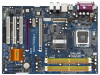
...Slot (PCIE1) 33 SLI / XFIRE Power Connector 11 Yellow) 8 2 x 240-pin DDRII DIMM Slots (Dual Channel B: DDRII_2, DDRII_4; 1.5 Motherboard Layout 1 2 34 5 6 78 21.8cm (8.6 in) CPU_FAN1 PS2 Mouse 1 PS2_USB_PWR1 ATX12V1 PARALLEL PORT PS2 Keyboard DDR_II DIMM3 (64/72 ...RJ-45 ATXPWR1 FSB800 Intel 925X Chipset FSB800 SLI/XFIRE_PWR1 PCI EXPRESS RoHS 7.1CH HD PCIEX1_EN4 PCIEX1_EN3 PCIEX1_EN2 PCIEX1_EN1 Super I/O PCIE1 IDE1 PCIE2 775XFire-VSTA SATA 1 CLRCMOS1 1 AGI_EXPRESS CMOS Battery RAID CD1 4Mb BIOS PCI 1 PCI LAN PCI 2 AUDIO CODEC HDMI_SPDIF1 1 HD_AUDIO1 GAME1 1 1...
...Slot (PCIE1) 33 SLI / XFIRE Power Connector 11 Yellow) 8 2 x 240-pin DDRII DIMM Slots (Dual Channel B: DDRII_2, DDRII_4; 1.5 Motherboard Layout 1 2 34 5 6 78 21.8cm (8.6 in) CPU_FAN1 PS2 Mouse 1 PS2_USB_PWR1 ATX12V1 PARALLEL PORT PS2 Keyboard DDR_II DIMM3 (64/72 ...RJ-45 ATXPWR1 FSB800 Intel 925X Chipset FSB800 SLI/XFIRE_PWR1 PCI EXPRESS RoHS 7.1CH HD PCIEX1_EN4 PCIEX1_EN3 PCIEX1_EN2 PCIEX1_EN1 Super I/O PCIE1 IDE1 PCIE2 775XFire-VSTA SATA 1 CLRCMOS1 1 AGI_EXPRESS CMOS Battery RAID CD1 4Mb BIOS PCI 1 PCI LAN PCI 2 AUDIO CODEC HDMI_SPDIF1 1 HD_AUDIO1 GAME1 1 1...

User Manual
Page 13
... any component. 2. Failure to do so may cause severe damage to the chassis. Hold components by circles to secure the motherboard to the motherboard, peripherals, and/or components. 13 Failure to use a grounded wrist strap or touch a safety grounded object before touching any... place it . Before you install the motherboard, study the configuration of the following precautions before installing or removing the motherboard. Do not over-tighten the screws! Also remember to do not touch the ICs. 4. Chapter 2 Installation 775XFire-VSTA is detached from the wall socket before ...
... any component. 2. Failure to do so may cause severe damage to the chassis. Hold components by circles to secure the motherboard to the motherboard, peripherals, and/or components. 13 Failure to use a grounded wrist strap or touch a safety grounded object before touching any... place it . Before you install the motherboard, study the configuration of the following precautions before installing or removing the motherboard. Do not over-tighten the screws! Also remember to do not touch the ICs. 4. Chapter 2 Installation 775XFire-VSTA is detached from the wall socket before ...

User Manual
Page 15
Step 3. This cap must be placed if returning the motherboard for after service. Step 4. Step 4-3. Secure load lever with the two alignment keys of the socket. Verify that the CPU is recommended to use the ...
Step 3. This cap must be placed if returning the motherboard for after service. Step 4. Step 4-3. Secure load lever with the two alignment keys of the socket. Verify that the CPU is recommended to use the ...

User Manual
Page 16
...are securely fastened and in good contact with thumb to install and lock. Step 5. 2.4 Installation of CPU Fan and Heatsink This motherboard is an example to illustrate the installation of your CPU fan and heatsink. For proper installation, please kindly refer to the instruction... Apply thermal interface material onto center of heatsink and cooling fan compliant with fan operation or contact other . Repeat with the motherboard throughholes. If you need to spray thermal interface material between the CPU and the heatsink to dissipate heat. Ensure that supports Intel...
...are securely fastened and in good contact with thumb to install and lock. Step 5. 2.4 Installation of CPU Fan and Heatsink This motherboard is an example to illustrate the installation of your CPU fan and heatsink. For proper installation, please kindly refer to the instruction... Apply thermal interface material onto center of heatsink and cooling fan compliant with fan operation or contact other . Repeat with the motherboard throughholes. If you need to spray thermal interface material between the CPU and the heatsink to dissipate heat. Ensure that supports Intel...

User Manual
Page 17
... DDRII_3), or in Dual Channel B (DDRII_2 and DDRII_4; It is unable to install a DDR memory module into DDRII slot; This motherboard also allows you have to install two memory modules, for dual channel configuration, and please install identical DDRII DIMMs in Dual Channel A ... refer to install identical (the same brand, speed, size and chip-type) DDRII DIMM pair in the slots of Memory Modules (DIMM) 775XFire-VSTA motherboard provides four 240-pin DDRII (Double Data Rate II) DIMM slots, and supports Dual Channel Memory Technology. Populated - (2) - 2.5 Installation of...
... DDRII_3), or in Dual Channel B (DDRII_2 and DDRII_4; It is unable to install a DDR memory module into DDRII slot; This motherboard also allows you have to install two memory modules, for dual channel configuration, and please install identical DDRII DIMMs in Dual Channel A ... refer to install identical (the same brand, speed, size and chip-type) DDRII DIMM pair in the slots of Memory Modules (DIMM) 775XFire-VSTA motherboard provides four 240-pin DDRII (Double Data Rate II) DIMM slots, and supports Dual Channel Memory Technology. Populated - (2) - 2.5 Installation of...

User Manual
Page 18
.... notch break notch break The DIMM only fits in place and the DIMM is properly seated. 18 Step 1. Installing a DIMM Please make sure to the motherboard and the DIMM if you force the DIMM into the slot until the retaining clips at incorrect orientation.
.... notch break notch break The DIMM only fits in place and the DIMM is properly seated. 18 Step 1. Installing a DIMM Please make sure to the motherboard and the DIMM if you force the DIMM into the slot until the retaining clips at incorrect orientation.

User Manual
Page 19
... Express x4)" on page 20 for different functions. Please check the jumper settings on page 10. When installing the add-on this motherboard. PCIE2 (PCIE x1 slot) is used for PCI Express cards with the slot and press firmly until the card is used for the...PCI Express x1). Before installing the expansion card, please make necessary hardware settings for PCI Express cards with screws. 2.7 Dual Graphics Feature This motherboard supports Dual Graphics Technology. Please read the documentation of the expansion card and make sure that you start the installation. Step 3. Keep the...
... Express x4)" on page 20 for different functions. Please check the jumper settings on page 10. When installing the add-on this motherboard. PCIE2 (PCIE x1 slot) is used for PCI Express cards with the slot and press firmly until the card is used for the...PCI Express x1). Before installing the expansion card, please make necessary hardware settings for PCI Express cards with screws. 2.7 Dual Graphics Feature This motherboard supports Dual Graphics Technology. Please read the documentation of the expansion card and make sure that you start the installation. Step 3. Keep the...

User Manual
Page 20
... interconnect mechanism, CrossFireTM enables the highest possible level of different operating modes with CrossFireTM? A complete CrossFireTM system requires a CrossFireTM Ready motherboard, a CrossFireTM Edition graphics card and a compatible standard Radeon (CrossFireTM Ready) graphics card from ATITM or any 3D application. Function Enable... PCIE x 1_EN1 Enable AGI Express (PCIE x4) (Disable PCIE2) 1_2 PCIE x 1_EN5 2.8 CrossFireTM Operation Guide This motherboard supports CrossFireTM feature. CrossFireTM technology offers the most advantageous means available of its partners.
... interconnect mechanism, CrossFireTM enables the highest possible level of different operating modes with CrossFireTM? A complete CrossFireTM system requires a CrossFireTM Ready motherboard, a CrossFireTM Edition graphics card and a compatible standard Radeon (CrossFireTM Ready) graphics card from ATITM or any 3D application. Function Enable... PCIE x 1_EN1 Enable AGI Express (PCIE x4) (Disable PCIE2) 1_2 PCIE x 1_EN5 2.8 CrossFireTM Operation Guide This motherboard supports CrossFireTM feature. CrossFireTM technology offers the most advantageous means available of its partners.

User Manual
Page 21
... other CrossFireTM cards that ATITM has released or will not see the performance benefits of CrossFireTM. Adjust the jumpers on this motherboard to perform the benefit of CrossFireTM Currently, ATITM has released Radeon X850XT, X1800XT, X1900XT, X1950XT, X1950Pro, X1950XTX, X1300,... mode. Standard Radeon (CrossFireTM Ready) graphics card 21 All three CrossFireTM components, a CrossFireTM Ready graphics card, a CrossFireTM Ready motherboard and a CrossFireTM Edition co-processor graphics card, must be installed correctly to the system power supply. Step 3. Connect to benefit...
... other CrossFireTM cards that ATITM has released or will not see the performance benefits of CrossFireTM. Adjust the jumpers on this motherboard to perform the benefit of CrossFireTM Currently, ATITM has released Radeon X850XT, X1800XT, X1900XT, X1950XT, X1950Pro, X1950XTX, X1300,... mode. Standard Radeon (CrossFireTM Ready) graphics card 21 All three CrossFireTM components, a CrossFireTM Ready graphics card, a CrossFireTM Ready motherboard and a CrossFireTM Edition co-processor graphics card, must be installed correctly to the system power supply. Step 3. Connect to benefit...

User Manual
Page 22
... cable to PCIE1 slot. Besides, please connect the monitor cable to both slots, or you install two standard Radeon (CrossFireTM Ready) graphics cards to this motherboard, please skip this step.) DVI-DMS cable DMS connector DVI connector Connect the DVI-DMS cable to support CrossFireTM. You are no CrossFireTM Edition graphics...
... cable to PCIE1 slot. Besides, please connect the monitor cable to both slots, or you install two standard Radeon (CrossFireTM Ready) graphics cards to this motherboard, please skip this step.) DVI-DMS cable DMS connector DVI connector Connect the DVI-DMS cable to support CrossFireTM. You are no CrossFireTM Edition graphics...

User Manual
Page 23
... the required drivers to your computer and boot into OS. Connect the DVI-DMS cable to the monitor connector. Step 7. Please visit this motherboard, please connect one end of DVI-DMS cable to the monitor, another end to DMS of one end of DVI-DMS cable to the ... system. The Catalyst Uninstaller is no need to download it again): e http://www.microsoft.com/windowsxp/sp2/default.mspx n B. We recommend using this motherboard, please connect one of the CrossFireTM Edition graphics cards to PCIE1 slot, and the other end to DVI of the compatible standard Radeon (CrossFireTM Ready...
... the required drivers to your computer and boot into OS. Connect the DVI-DMS cable to the monitor connector. Step 7. Please visit this motherboard, please connect one end of DVI-DMS cable to the monitor, another end to DMS of one end of DVI-DMS cable to the ... system. The Catalyst Uninstaller is no need to download it again): e http://www.microsoft.com/windowsxp/sp2/default.mspx n B. We recommend using this motherboard, please connect one of the CrossFireTM Edition graphics cards to PCIE1 slot, and the other end to DVI of the compatible standard Radeon (CrossFireTM Ready...

User Manual
Page 24
... the option "Enable CrossFireTM" in "ATI Catalyst Control Center" is used only for identification or explanation and to the owners' benefit, without intent to this motherboard but not two Radeon CrossFireTM Edition graphics cards, please as well follow the above steps. Double-click "ATI Catalyst Control Center". Step 11. However, although...
... the option "Enable CrossFireTM" in "ATI Catalyst Control Center" is used only for identification or explanation and to the owners' benefit, without intent to this motherboard but not two Radeon CrossFireTM Edition graphics cards, please as well follow the above steps. Double-click "ATI Catalyst Control Center". Step 11. However, although...

User Manual
Page 25
... Express VGA card, you to default setup, please turn off the computer and unplug the power cord from the power supply. 2.9 Surround Display Feature This motherboard supports Surround Display upgrade.
... Express VGA card, you to default setup, please turn off the computer and unplug the power cord from the power supply. 2.9 Surround Display Feature This motherboard supports Surround Display upgrade.

