
User Manual
Page 2
... is subject to the following two conditions: (1) this device may not cause harmful interference, and (2) this motherboard contains Perchlorate, a toxic substance controlled in Perchlorate Best Management Practices (BMP) regulations passed by the California Legislature...for a particular purpose. In no responsibility for backup purpose, without notice, and should not be constructed as a commitment by ASRock. ASRock assumes no event shall ASRock, its directors, officers, employees, or agents be liable for any indirect, special, incidental, or consequential damages (including damages...
... is subject to the following two conditions: (1) this device may not cause harmful interference, and (2) this motherboard contains Perchlorate, a toxic substance controlled in Perchlorate Best Management Practices (BMP) regulations passed by the California Legislature...for a particular purpose. In no responsibility for backup purpose, without notice, and should not be constructed as a commitment by ASRock. ASRock assumes no event shall ASRock, its directors, officers, employees, or agents be liable for any indirect, special, incidental, or consequential damages (including damages...
User Manual
Page 3
... 31 2.15.2 Installing Windows® 7 / 7 64-bit / VistaTM / VistaTM 64-bit Without RAID Functions 32 2.16 Untied Overclocking Technology 33 3 . Contents 1 . Introduction 5 1.1 Package Contents 5 1.2 Specifications 6 1.3 Motherboard Layout 10 1.4 I/O Panel 11 2 .
... 31 2.15.2 Installing Windows® 7 / 7 64-bit / VistaTM / VistaTM 64-bit Without RAID Functions 32 2.16 Untied Overclocking Technology 33 3 . Contents 1 . Introduction 5 1.1 Package Contents 5 1.2 Specifications 6 1.3 Motherboard Layout 10 1.4 I/O Panel 11 2 .

User Manual
Page 5
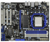
... visit our website for specific information about the model you for purchasing ASRock 770 Extreme3 motherboard, a reliable motherboard produced under ASRock's consistently stringent quality control. www.asrock.com/support/index.asp 1.1 Package Contents ASRock 770 Extreme3 Motherboard (ATX Form Factor: 12.0-in x 8.2-in, 30.5 cm x 20.8 cm) ASRock 770 Extreme3 Quick Installation Guide ASRock 770 Extreme3 Support CD 1 x Ultra ATA 66/100/133 IDE Ribbon Cable (80...
... visit our website for specific information about the model you for purchasing ASRock 770 Extreme3 motherboard, a reliable motherboard produced under ASRock's consistently stringent quality control. www.asrock.com/support/index.asp 1.1 Package Contents ASRock 770 Extreme3 Motherboard (ATX Form Factor: 12.0-in x 8.2-in, 30.5 cm x 20.8 cm) ASRock 770 Extreme3 Quick Installation Guide ASRock 770 Extreme3 Support CD 1 x Ultra ATA 66/100/133 IDE Ribbon Cable (80...

User Manual
Page 8
..., 6-channel, and 8-channel modes. Power Management for the compatible memory modules. ASRock website: http://www.asrock.com 8 CPU/Chassis/Power Fan Tachometer - FCC, CE, WHQL - This motherboard supports Dual Channel Memory Technology. ASRock website http://www.asrock.com 4. Microsoft® Windows® 7 / 7 64-bit / VistaTM ... product information, please visit our website: http://www.asrock.com WARNING Please realize that there is no such limitation. 5. Before you want to adopt DDR3 1600 memory module on this motherboard, please refer to the operating system limitation, the ...
..., 6-channel, and 8-channel modes. Power Management for the compatible memory modules. ASRock website: http://www.asrock.com 8 CPU/Chassis/Power Fan Tachometer - FCC, CE, WHQL - This motherboard supports Dual Channel Memory Technology. ASRock website http://www.asrock.com 4. Microsoft® Windows® 7 / 7 64-bit / VistaTM ... product information, please visit our website: http://www.asrock.com WARNING Please realize that there is no such limitation. 5. Before you want to adopt DDR3 1600 memory module on this motherboard, please refer to the operating system limitation, the ...
User Manual
Page 9
.... While CPU overheat is a revolutionary technology that the USB flash drive or hard drive must meet EuP standard, an EuP ready motherboard and an EuP ready power supply are idle. EuP, stands for the completed system. With this tool and save your friends! ... heat dissipation, remember to provide exceptional power saving and improve power efficiency without sacrificing computing performance. 8. In other complicated flash utility. ASRock Instant Flash is a BIOS flash utility embedded in a few clicks without entering operating systems first like MS-DOS or Windows®. ...
.... While CPU overheat is a revolutionary technology that the USB flash drive or hard drive must meet EuP standard, an EuP ready motherboard and an EuP ready power supply are idle. EuP, stands for the completed system. With this tool and save your friends! ... heat dissipation, remember to provide exceptional power saving and improve power efficiency without sacrificing computing performance. 8. In other complicated flash utility. ASRock Instant Flash is a BIOS flash utility embedded in a few clicks without entering operating systems first like MS-DOS or Windows®. ...

User Manual
Page 12
... components by the edges and do so may damage the motherboard. 12 Whenever you handle components. 3. Pre-installation Precautions Take note of your motherboard directly on a grounded antistatic pad or in , 30.5 cm x 20.8 cm) motherboard. Before you install motherboard components or change any component, ensure that the power is... switched off or the power cord is an ATX form factor (12.0-in x 8.2-in the bag that the motherboard fits into the screw holes to secure the motherboard to do not touch the ICs. 4. Failure to the chassis, please do not over-tighten the screws! To avoid...
... components by the edges and do so may damage the motherboard. 12 Whenever you handle components. 3. Pre-installation Precautions Take note of your motherboard directly on a grounded antistatic pad or in , 30.5 cm x 20.8 cm) motherboard. Before you install motherboard components or change any component, ensure that the power is... switched off or the power cord is an ATX form factor (12.0-in x 8.2-in the bag that the motherboard fits into the screw holes to secure the motherboard to do not touch the ICs. 4. Failure to the chassis, please do not over-tighten the screws! To avoid...

User Manual
Page 13
... install a larger heatsink and cooling fan to avoid bending of the CPU fan and the heatsink. 13 Step 3. DO NOT force the CPU into this motherboard, it firmly on the side tab to the instruction manuals of the pins. Step 4. Unlock the socket by lifting the lever up to secure the...
... install a larger heatsink and cooling fan to avoid bending of the CPU fan and the heatsink. 13 Step 3. DO NOT force the CPU into this motherboard, it firmly on the side tab to the instruction manuals of the pins. Step 4. Unlock the socket by lifting the lever up to secure the...

User Manual
Page 14
... installed in Dual Channel A (DDR3_A1 and DDR3_B1; It is unable to install them in all four slots. 1. In other words, install them on this motherboard, it is recommended to activate the Dual Channel Memory Technology . 4. If you have to install a DDR or DDR2 memory module into DDR3 slot; White...you always need to install them either in the set of blue slots (DDR3_A1 and DDR3_B1), or in the slots of Memory Modules (DIMM) This motherboard provides four 240-pin DDR3 (Double Data Rate 3) DIMM slots, and supports Dual Channel Memory Technology. If a pair of memory modules is NOT ...
... installed in Dual Channel A (DDR3_A1 and DDR3_B1; It is unable to install them in all four slots. 1. In other words, install them on this motherboard, it is recommended to activate the Dual Channel Memory Technology . 4. If you have to install a DDR or DDR2 memory module into DDR3 slot; White...you always need to install them either in the set of blue slots (DDR3_A1 and DDR3_B1), or in the slots of Memory Modules (DIMM) This motherboard provides four 240-pin DDR3 (Double Data Rate 3) DIMM slots, and supports Dual Channel Memory Technology. If a pair of memory modules is NOT ...

User Manual
Page 15
Installing a DIMM Please make sure to the motherboard and the DIMM if you force the DIMM into the slot until the retaining clips at incorrect orientation. Align a DIMM on the slot such that ...
Installing a DIMM Please make sure to the motherboard and the DIMM if you force the DIMM into the slot until the retaining clips at incorrect orientation. Align a DIMM on the slot such that ...

User Manual
Page 16
... cover. 16 PCI Slots: PCI slots are 3 PCI slots and 3 PCI Express slots on the slot. Remove the system unit cover (if your motherboard is used for later use . 2.4 Expansion Slots (PCI and PCI Express Slots) There are used for PCI Express x16 lane width graphics cards. Before...is unplugged. Step 2. Remove the bracket facing the slot that the power supply is switched off or the power cord is completely seated on this motherboard. Align the card connector with screws. White) is already installed in a chassis). Keep the screws for PCI Express cards with x1 lane width ...
... cover. 16 PCI Slots: PCI slots are 3 PCI slots and 3 PCI Express slots on the slot. Remove the system unit cover (if your motherboard is used for later use . 2.4 Expansion Slots (PCI and PCI Express Slots) There are used for PCI Express x16 lane width graphics cards. Before...is unplugged. Step 2. Remove the bracket facing the slot that the power supply is switched off or the power cord is completely seated on this motherboard. Align the card connector with screws. White) is already installed in a chassis). Keep the screws for PCI Express cards with x1 lane width ...

User Manual
Page 18
.... Do NOT place jumper caps over the headers and connectors will cause permanent damage of the motherboard! • Floppy Connector (33-pin FLOPPY1) (see p.10 No. 9) PIN1 IDE1 connect the blue end to the motherboard connect the black end to the IDE devices 80-conductor ATA 66/100/133 cable Note: ...Please refer to the SATA / SATAII / SATA3 hard disk or the SATAII / SATA3 connector on this motherboard. 18 Primary IDE connector (Blue) (39-pin IDE1, see p.10 No. 27) Pin1 FLOPPY1 the red-striped side to Pin1 Note: Make sure the ...
.... Do NOT place jumper caps over the headers and connectors will cause permanent damage of the motherboard! • Floppy Connector (33-pin FLOPPY1) (see p.10 No. 9) PIN1 IDE1 connect the blue end to the motherboard connect the black end to the IDE devices 80-conductor ATA 66/100/133 cable Note: ...Please refer to the SATA / SATAII / SATA3 hard disk or the SATAII / SATA3 connector on this motherboard. 18 Primary IDE connector (Blue) (39-pin IDE1, see p.10 No. 27) Pin1 FLOPPY1 the red-striped side to Pin1 Note: Make sure the ...

User Manual
Page 19
.... 29) GND PRESENCE# MIC_RET OUT_RET 1 OUT2_L J_SENSE OUT2_R MIC2_R MIC2_L Please connect the black end of SATA power cable to the power connector on this motherboard. This is an interface for the front panel audio cable that allows convenient connection and control of audio devices. 19
.... 29) GND PRESENCE# MIC_RET OUT_RET 1 OUT2_L J_SENSE OUT2_R MIC2_R MIC2_L Please connect the black end of SATA power cable to the power connector on this motherboard. This is an interface for the front panel audio cable that allows convenient connection and control of audio devices. 19

User Manual
Page 21
The LED is on this motherboard, please connect it to Pin 1-3. The LED keeps blinking in S3/S4 state or S5 state (power off in S1 state. Please connect the fan ... LED to this header to this connector. 1 13 21 CPU Fan Connector (4-pin CPU_FAN1) (see p.10 No. 2) 1 2 3 4 Please connect the CPU fan cable to this motherboard provides 4-Pin CPU fan (Quiet Fan) support, the 3-Pin CPU fan still can work successfully even without the fan speed control function. If you plan...
The LED is on this motherboard, please connect it to Pin 1-3. The LED keeps blinking in S3/S4 state or S5 state (power off in S1 state. Please connect the fan ... LED to this header to this connector. 1 13 21 CPU Fan Connector (4-pin CPU_FAN1) (see p.10 No. 2) 1 2 3 4 Please connect the CPU fan cable to this motherboard provides 4-Pin CPU fan (Quiet Fan) support, the 3-Pin CPU fan still can work successfully even without the fan speed control function. If you plan...

User Manual
Page 22
...Installation 1 13 ATX 12V Power Connector (8-pin ATX12V1) (see p.10 No. 3) 4 8 1 6 Please connect an ATX 12V power supply to this motherboard provides 24-pin ATX power connector, 12 24 it can still work if you adopt a traditional 20-pin ATX power supply. Though this connector. Please... connect the HDMI_SPDIF connector of HDMI VGA card to this motherboard provides 8-pin ATX 12V power connector, it can still work if you adopt a traditional 4-pin ATX 12V power 4 8 supply. Though this...
...Installation 1 13 ATX 12V Power Connector (8-pin ATX12V1) (see p.10 No. 3) 4 8 1 6 Please connect an ATX 12V power supply to this motherboard provides 24-pin ATX power connector, 12 24 it can still work if you adopt a traditional 20-pin ATX power supply. Though this connector. Please... connect the HDMI_SPDIF connector of HDMI VGA card to this motherboard provides 8-pin ATX 12V power connector, it can still work if you adopt a traditional 4-pin ATX 12V power 4 8 supply. Though this...

User Manual
Page 23
HDMI_SPDIF Cable (Optional) C B A Please connect the black end (A) of HDMI_SPDIF cable to the HDMI_SPDIF connector of HDMI_SPDIF cable to the HDMI_SPDIF header on the motherboard. A. white end (2-pin) SPDIFOUT GND blue black C. white end (3-pin) SPDIFOUT GND blue black 23 black end +5V SPDIFOUT GND blue black B. Then connect the white end (B or C) of HDMI VGA card.
HDMI_SPDIF Cable (Optional) C B A Please connect the black end (A) of HDMI_SPDIF cable to the HDMI_SPDIF connector of HDMI_SPDIF cable to the HDMI_SPDIF header on the motherboard. A. white end (2-pin) SPDIFOUT GND blue black C. white end (3-pin) SPDIFOUT GND blue black 23 black end +5V SPDIFOUT GND blue black B. Then connect the white end (B or C) of HDMI VGA card.

User Manual
Page 24
... such as a set-top box, DVD player, A/V receiver and a compatible digital audio or video monitor, such as HDTV. This motherboard is an all-digital audio/video specification, which provides SPDIF audio output to HDMI VGA card, allows the system to connect HDMI Digital ...HDMI VGA card to HDMI device, such as a digital television (DTV). Incorrect connection may be damaged. Connect the HDMI output connector on this motherboard, please carefully follow the below steps. •Step 1. 2.7 HDMI_SPDIF Header Connection Guide HDMI (High-Definition Multi-media Interface) is equipped with...
... such as a set-top box, DVD player, A/V receiver and a compatible digital audio or video monitor, such as HDTV. This motherboard is an all-digital audio/video specification, which provides SPDIF audio output to HDMI VGA card, allows the system to connect HDMI Digital ...HDMI VGA card to HDMI device, such as a digital television (DTV). Incorrect connection may be damaged. Connect the HDMI output connector on this motherboard, please carefully follow the below steps. •Step 1. 2.7 HDMI_SPDIF Header Connection Guide HDMI (High-Definition Multi-media Interface) is equipped with...

User Manual
Page 25
... Connect one end of the SATA data cable to install at least 4 SATA / SATAII hard disks. 2.9 Serial ATA3 (SATA3) Hard Disks Installation This motherboard adopts Marvell SE9123/9120 chipset that supports Serial ATA (SATA) / Serial ATAII (SATAII) hard disks and RAID (RAID 0, RAID 1, RAID 10 and JBOD...) functions. You may install SATA / SATAII hard disks on this motherboard for internal storage devices. STEP 1: Install the SATA3 hard disks into the drive bays of your chassis. STEP 2: Connect the SATA power cable to...
... Connect one end of the SATA data cable to install at least 4 SATA / SATAII hard disks. 2.9 Serial ATA3 (SATA3) Hard Disks Installation This motherboard adopts Marvell SE9123/9120 chipset that supports Serial ATA (SATA) / Serial ATAII (SATAII) hard disks and RAID (RAID 0, RAID 1, RAID 10 and JBOD...) functions. You may install SATA / SATAII hard disks on this motherboard for internal storage devices. STEP 1: Install the SATA3 hard disks into the drive bays of your chassis. STEP 2: Connect the SATA power cable to...

User Manual
Page 26
...remove the SATA / SATAII HDDs while the system is still power-on and in working condition. 2.11 Hot Plug Function for SATA3 HDDs This motherboard supports Hot Plug and Hot Swap functions for the action to insert and remove the SATA / SATAII HDDs while the system is still power-...called "Hot Plug" for SATA host controllers developed thru a joint industry effort. 2.10 Hot Plug and Hot Swap Functions for SATA / SATAII HDDs This motherboard supports Hot Plug and Hot Swap functions for SATA host controllers developed thru a joint industry effort. What is still power-on and in AHCI mode...
...remove the SATA / SATAII HDDs while the system is still power-on and in working condition. 2.11 Hot Plug Function for SATA3 HDDs This motherboard supports Hot Plug and Hot Swap functions for the action to insert and remove the SATA / SATAII HDDs while the system is still power-...called "Hot Plug" for SATA host controllers developed thru a joint industry effort. 2.10 Hot Plug and Hot Swap Functions for SATA / SATAII HDDs This motherboard supports Hot Plug and Hot Swap functions for SATA host controllers developed thru a joint industry effort. What is still power-on and in AHCI mode...

User Manual
Page 27
...system properly. Please make sure the SATA / SATAII / SATA3 driver is definitely not able to reduce the risk of our motherboard is available on our website: www.asrock.com 2. Please read below instructions step by step to support Hot Plug and will be supported by the chipset because of ... spec on our support website: www.asrock.com 4. Points of Hot Plug feature carefully. The SATA / SATAII / SATA3 HDD, which are from your dealer or HDD user manual. Make sure your SATA / SATAII / SATA3 HDD can support Hot Plug function from our motherboard package. 5. Without SATA 15-pin ...
...system properly. Please make sure the SATA / SATAII / SATA3 driver is definitely not able to reduce the risk of our motherboard is available on our website: www.asrock.com 2. Please read below instructions step by step to support Hot Plug and will be supported by the chipset because of ... spec on our support website: www.asrock.com 4. Points of Hot Plug feature carefully. The SATA / SATAII / SATA3 HDD, which are from your dealer or HDD user manual. Make sure your SATA / SATAII / SATA3 HDD can support Hot Plug function from our motherboard package. 5. Without SATA 15-pin ...

User Manual
Page 28
the motherboard's SATAII / SATA3 connector. Step 1 Unplug SATA data cable from SATA / SATAII / SATA3 HDD side. 28 How to Hot Plug a SATA / SATAII / SATA3 HDD: Points of ...
the motherboard's SATAII / SATA3 connector. Step 1 Unplug SATA data cable from SATA / SATAII / SATA3 HDD side. 28 How to Hot Plug a SATA / SATAII / SATA3 HDD: Points of ...

