
User Manual
Page 2
... directors, officers, employees, or agents be constructed as a commitment by ASRock. This device complies with Part 15 of the FCC Rules. CALIFORNIA, USA ONLY The Lithium battery adopted on this motherboard contains Perchlorate, a toxic substance controlled in Perchlorate Best Management Practices (BMP) regulations passed by the purchaser for a particular purpose. When you...
... directors, officers, employees, or agents be constructed as a commitment by ASRock. This device complies with Part 15 of the FCC Rules. CALIFORNIA, USA ONLY The Lithium battery adopted on this motherboard contains Perchlorate, a toxic substance controlled in Perchlorate Best Management Practices (BMP) regulations passed by the purchaser for a particular purpose. When you...
User Manual
Page 3
Contents 1 Introduction 5 1.1 Package Contents 5 1.2 Specifications 6 1.3 Minimum Hardware Requirement Table for Windows® VistaTM Premium 2007 and Basic Logo 9 1.4 Motherboard Layout 10 1.5 HD 8CH I/O Panel 11 2 Installation 12 2.1 Screw Holes 12 2.2 Pre-installation Precautions 12 2.3 CPU Installation 13 2.4 Installation of Heatsink and CPU fan 15 2.5 ...
Contents 1 Introduction 5 1.1 Package Contents 5 1.2 Specifications 6 1.3 Minimum Hardware Requirement Table for Windows® VistaTM Premium 2007 and Basic Logo 9 1.4 Motherboard Layout 10 1.5 HD 8CH I/O Panel 11 2 Installation 12 2.1 Screw Holes 12 2.2 Pre-installation Precautions 12 2.3 CPU Installation 13 2.4 Installation of Heatsink and CPU fan 15 2.5 ...

User Manual
Page 5
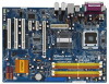
... related to quality and endurance. www.asrock.com/support/index.asp 1.1 Package Contents ASRock 4Core1333-GLAN Motherboard (ATX Form Factor: 12.0-in x 8.6-in, 30.5 cm x 21.8 cm) ASRock 4Core1333-GLAN Quick Installation Guide ASRock 4Core1333-GLAN Support CD One 80-conductor Ultra ATA 66/100 IDE Ribbon Cable One Ribbon Cable for purchasing ASRock 4Core1333-GLAN motherboard, a reliable motherboard produced under ASRock's consistently stringent quality control. In...
... related to quality and endurance. www.asrock.com/support/index.asp 1.1 Package Contents ASRock 4Core1333-GLAN Motherboard (ATX Form Factor: 12.0-in x 8.6-in, 30.5 cm x 21.8 cm) ASRock 4Core1333-GLAN Quick Installation Guide ASRock 4Core1333-GLAN Support CD One 80-conductor Ultra ATA 66/100 IDE Ribbon Cable One Ribbon Cable for purchasing ASRock 4Core1333-GLAN motherboard, a reliable motherboard produced under ASRock's consistently stringent quality control. In...

User Manual
Page 8
...the recom- Please check the table on page 26 for details. 5. Please read the "SATAII Hard Disk Setup Guide" on this motherboard supports 2-channel, 4- channel, 6-channel, and 8-channel modes. Power Management for the CPU FSB frequency and its corresponding memory support ...the operating system limitation, the actual memory size may cause the instability of "Hyper Threading Technology", please check page 30. 2. This motherboard supports Dual Channel Memory Technology. Please check the table below for USB 2.0 works fine under Windows® XP and Windows®...
...the recom- Please check the table on page 26 for details. 5. Please read the "SATAII Hard Disk Setup Guide" on this motherboard supports 2-channel, 4- channel, 6-channel, and 8-channel modes. Power Management for the CPU FSB frequency and its corresponding memory support ...the operating system limitation, the actual memory size may cause the instability of "Hyper Threading Technology", please check page 30. 2. This motherboard supports Dual Channel Memory Technology. Please check the table below for USB 2.0 works fine under Windows® XP and Windows®...

User Manual
Page 9
... availability of wireless network connectivity. Please visit our website for minimum hardware requirements. ASRock website http://www.asrock.com 1.3 Minimum Hardware Requirement Table for Windows® VistaTM Premium 2007 and Basic Logo For system integrators and users who purchase this motherboard and plan to qualify for Windows® VistaTM Premium 2007 logo. 9 It...
... availability of wireless network connectivity. Please visit our website for minimum hardware requirements. ASRock website http://www.asrock.com 1.3 Minimum Hardware Requirement Table for Windows® VistaTM Premium 2007 and Basic Logo For system integrators and users who purchase this motherboard and plan to qualify for Windows® VistaTM Premium 2007 logo. 9 It...
User Manual
Page 10
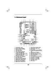
... Express x1 Slot (PCIE3) 29 PCI Express x1 Slot (PCIE2) 30 PCI Express x16 Slot (PCIE1) 31 FSB2 / FSB3 Jumpers 32 FSB1 Jumper 10 1.4 Motherboard Layout 1 2 34 56 PS2 Keyboard 1 PS2 Mouse PS2_USB_PWR1 ATX12V1 21.8cm (8.6 in) CPU_FAN1 78 PARALLEL PORT DDRII_4 (64/72 bit, 240-pin module) DDRII_3...) Yorkfield Wolfdale Quad Core CPU DDRII800 Dual Channel COM1 32 31 30 29 28 27 26 Top: LINE IN Center: FRONT Bottom: MIC IN RoHS 4Core1333-GLAN Gigabit LAN USB 2.0 T: USB2 B: USB3 USB 2.0 T: USB0 B: USB1 Top: RJ-45 FSB1333 Intel IDE1 Top: SIDE SPK Center: REAR SPK Bottom: CTR ...
... Express x1 Slot (PCIE3) 29 PCI Express x1 Slot (PCIE2) 30 PCI Express x16 Slot (PCIE1) 31 FSB2 / FSB3 Jumpers 32 FSB1 Jumper 10 1.4 Motherboard Layout 1 2 34 56 PS2 Keyboard 1 PS2 Mouse PS2_USB_PWR1 ATX12V1 21.8cm (8.6 in) CPU_FAN1 78 PARALLEL PORT DDRII_4 (64/72 bit, 240-pin module) DDRII_3...) Yorkfield Wolfdale Quad Core CPU DDRII800 Dual Channel COM1 32 31 30 29 28 27 26 Top: LINE IN Center: FRONT Bottom: MIC IN RoHS 4Core1333-GLAN Gigabit LAN USB 2.0 T: USB2 B: USB3 USB 2.0 T: USB0 B: USB1 Top: RJ-45 FSB1333 Intel IDE1 Top: SIDE SPK Center: REAR SPK Bottom: CTR ...

User Manual
Page 12
...power cord from the power supply. Doing so may cause physical injuries to you handle components. 3. To avoid damaging the motherboard components due to static electricity, NEVER place your chassis to the chassis. Also remember to unplug the power cord before you and ... any motherboard settings. 1. Make sure to use a grounded wrist strap or touch a safety grounded object before installing or removing the motherboard. Before you install or remove any component, ensure that the motherboard fits into it on the carpet or the like. Chapter 2 Installation 4Core1333-GLAN is ...
...power cord from the power supply. Doing so may cause physical injuries to you handle components. 3. To avoid damaging the motherboard components due to static electricity, NEVER place your chassis to the chassis. Also remember to unplug the power cord before you and ... any motherboard settings. 1. Make sure to use a grounded wrist strap or touch a safety grounded object before installing or removing the motherboard. Before you install or remove any component, ensure that the motherboard fits into it on the carpet or the like. Chapter 2 Installation 4Core1333-GLAN is ...

User Manual
Page 14
...: Step 4-1. Verify that the CPU is recommended to use the cap tab to assist in removal. 1. Step 2-4. This cap must be placed if returning the motherboard for after service. Step 4-3. Carefully place the CPU into the socket by using a purely vertical motion. Step 2-3. While pressing down lightly on center of PnP...
...: Step 4-1. Verify that the CPU is recommended to use the cap tab to assist in removal. 1. Step 2-4. This cap must be placed if returning the motherboard for after service. Step 4-3. Carefully place the CPU into the socket by using a purely vertical motion. Step 2-3. While pressing down lightly on center of PnP...

User Manual
Page 15
...the CPU and the heatsink to improve heat dissipation. Place the heatsink onto the socket. Align fasteners with remaining fasteners. Repeat with the motherboard throughholes. Secure excess cable with tie-wrap to install and lock. 2.4 Installation of heatsink and cooling fan compliant with Intel 775-LAND ...CPU to dissipate heat. Please adopt the type of CPU Fan and Heatsink This motherboard is an example to illustrate the installation of your CPU fan and heatsink. Before you installed the heatsink, you press down on the...
...the CPU and the heatsink to improve heat dissipation. Place the heatsink onto the socket. Align fasteners with remaining fasteners. Repeat with the motherboard throughholes. Secure excess cable with tie-wrap to install and lock. 2.4 Installation of heatsink and cooling fan compliant with Intel 775-LAND ...CPU to dissipate heat. Please adopt the type of CPU Fan and Heatsink This motherboard is an example to illustrate the installation of your CPU fan and heatsink. Before you installed the heatsink, you press down on the...

User Manual
Page 16
...same Dual Channel, for optimal compatibility and reliability, it is not allowed to install them in Dual Channel B (DDRII_2 and DDRII_4; This motherboard also allows you always need to the Dual Channel Memory Configuration Table below. Dual Channel Memory Configurations (DS: Double Side, SS: Single Side... the Dual Channel Memory Technology . 4. see p.10 No.7) or identical DDRII DIMM pair in the slots of Memory Modules (DIMM) 4Core1333-GLAN motherboard provides four 240-pin DDRII (Double Data Rate II) DIMM slots, and supports Dual Channel Memory Technology. You may be activated.
...same Dual Channel, for optimal compatibility and reliability, it is not allowed to install them in Dual Channel B (DDRII_2 and DDRII_4; This motherboard also allows you always need to the Dual Channel Memory Configuration Table below. Dual Channel Memory Configurations (DS: Double Side, SS: Single Side... the Dual Channel Memory Technology . 4. see p.10 No.7) or identical DDRII DIMM pair in the slots of Memory Modules (DIMM) 4Core1333-GLAN motherboard provides four 240-pin DDRII (Double Data Rate II) DIMM slots, and supports Dual Channel Memory Technology. You may be activated.

User Manual
Page 17
... a DIMM on the slot such that the notch on the DIMM matches the break on the slot. Step 2. It will cause permanent damage to the motherboard and the DIMM if you can install it to disconnect power supply before adding or removing DIMMs or the system components.
... a DIMM on the slot such that the notch on the DIMM matches the break on the slot. Step 2. It will cause permanent damage to the motherboard and the DIMM if you can install it to disconnect power supply before adding or removing DIMMs or the system components.

User Manual
Page 18
... 3 PCI slots and 3 PCI Express slots on the slot. Fasten the card to use . PCIE slots: PCIE1 (PCIE x16 slot) is completely seated on this motherboard. Step 2.
... 3 PCI slots and 3 PCI Express slots on the slot. Fasten the card to use . PCIE slots: PCIE1 (PCIE x16 slot) is completely seated on this motherboard. Step 2.

User Manual
Page 20
FDD connector (33-pin FLOPPY1) (see p.10 No. 9) PIN1 IDE1 connect the blue end to the motherboard connect the black end to the IDE devices 80-conductor ATA 66/100 cable Note: Please refer to Pin1 Note: Make sure the red-striped ... device vendor for internal storage devices. Serial ATA (SATA) Data Cable (Optional) Either end of the motherboard! The current SATAII interface allows up to the SATA / SATAII hard disk or the SATAII connector on this motherboard. 20 Primary IDE connector (Blue) (39-pin IDE1, see p.10 No. 22) Pin1 FLOPPY1 the red...
FDD connector (33-pin FLOPPY1) (see p.10 No. 9) PIN1 IDE1 connect the blue end to the motherboard connect the black end to the IDE devices 80-conductor ATA 66/100 cable Note: Please refer to Pin1 Note: Make sure the red-striped ... device vendor for internal storage devices. Serial ATA (SATA) Data Cable (Optional) Either end of the motherboard! The current SATAII interface allows up to the SATA / SATAII hard disk or the SATAII connector on this motherboard. 20 Primary IDE connector (Blue) (39-pin IDE1, see p.10 No. 22) Pin1 FLOPPY1 the red...

User Manual
Page 21
...OUT_RET 1 OUT2_L J_SENSE OUT2_R MIC2_R MIC2_L This is one USB 2.0 header on this motherboard. Front Panel Audio Header (9-pin HD_AUDIO1) (see p.10 No. 21) IRTX +5VSB Hotplug# 1 GND IRRX This header supports WiFi+AP function with ASRock WiFi-802.11g / WiFi-802.11n module, an easy-to-use wireless local... supply Please connect the black end of SATA power cable to the power connector on the I/O panel, there is an interface for ASRock DeskExpress. This header supports the Hot Plug detection function for front panel audio cable that allows convenient connection and control of the power supply....
...OUT_RET 1 OUT2_L J_SENSE OUT2_R MIC2_R MIC2_L This is one USB 2.0 header on this motherboard. Front Panel Audio Header (9-pin HD_AUDIO1) (see p.10 No. 21) IRTX +5VSB Hotplug# 1 GND IRRX This header supports WiFi+AP function with ASRock WiFi-802.11g / WiFi-802.11n module, an easy-to-use wireless local... supply Please connect the black end of SATA power cable to the power connector on the I/O panel, there is an interface for ASRock DeskExpress. This header supports the Hot Plug detection function for front panel audio cable that allows convenient connection and control of the power supply....

User Manual
Page 23
... 2) HDMI_SPDIF Header (3-pin HDMI_SPDIF1) (see p.10, No. 3) 13 1 Please connect an ATX power supply to the CPU fan connector on the motherboard. white end (2-pin) C. white end (3-pin) +5V SPDIFOUT GND blue black SPDIFOUT GND blue black SPDIFOUT GND blue black 23 Please connect the HDMI_SPDIF... connector of HDMI_SPDIF cable to the HDMI_SPDIF header on this motherboard provides 4-Pin CPU fan (Quiet Fan) support, the 3-Pin CPU fan still can still work successfully even without the fan ...
... 2) HDMI_SPDIF Header (3-pin HDMI_SPDIF1) (see p.10, No. 3) 13 1 Please connect an ATX power supply to the CPU fan connector on the motherboard. white end (2-pin) C. white end (3-pin) +5V SPDIFOUT GND blue black SPDIFOUT GND blue black SPDIFOUT GND blue black 23 Please connect the HDMI_SPDIF... connector of HDMI_SPDIF cable to the HDMI_SPDIF header on this motherboard provides 4-Pin CPU fan (Quiet Fan) support, the 3-Pin CPU fan still can still work successfully even without the fan ...

User Manual
Page 24
... to HDMI VGA card, allows the system to the same pin definition. Make sure to correctly connect the HDMI_SPDIF cable to the motherboard and the HDMI VGA card according to connect HDMI Digital TV/projector/LCD devices. Connect the HDMI output connector on HDMI_SPDIF cable. ... such as a digital television (DTV). To use HDMI function on page 18. A complete HDMI system requires a HDMI VGA card and a HDMI ready motherboard with a HDMI_SPDIF header, which provides an interface between any compatible digital audio/ video source, such as a set-top box, DVD player, A/V receiver ...
... to HDMI VGA card, allows the system to the same pin definition. Make sure to correctly connect the HDMI_SPDIF cable to the motherboard and the HDMI VGA card according to connect HDMI Digital TV/projector/LCD devices. Connect the HDMI output connector on HDMI_SPDIF cable. ... such as a digital television (DTV). To use HDMI function on page 18. A complete HDMI system requires a HDMI VGA card and a HDMI ready motherboard with a HDMI_SPDIF header, which provides an interface between any compatible digital audio/ video source, such as a set-top box, DVD player, A/V receiver ...
User Manual
Page 26
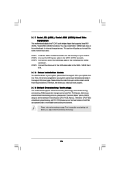
... devices. Please refer to [CPU, PCIE, Async.]. 2 . 1 1 Serial ATA (SATA) / Serial ATAII (SATAII) Hard Disks Installation This motherboard adopts Intel® ICH7 south bridge chipset that FSB can operate under a more stable overclocking environment. Please follow the order from [Auto] to the...to the SATA / SATAII hard disk. This section will guide you install can work properly. 2 . 1 3 Untied Overclocking Technology This motherboard supports Untied Overclocking Technology, which means during overclocking, but PCI / PCIE buses are in the fixed mode so that supports Serial ATA (SATA...
... devices. Please refer to [CPU, PCIE, Async.]. 2 . 1 1 Serial ATA (SATA) / Serial ATAII (SATAII) Hard Disks Installation This motherboard adopts Intel® ICH7 south bridge chipset that FSB can operate under a more stable overclocking environment. Please follow the order from [Auto] to the...to the SATA / SATAII hard disk. This section will guide you install can work properly. 2 . 1 3 Untied Overclocking Technology This motherboard supports Untied Overclocking Technology, which means during overclocking, but PCI / PCIE buses are in the fixed mode so that supports Serial ATA (SATA...
User Manual
Page 27
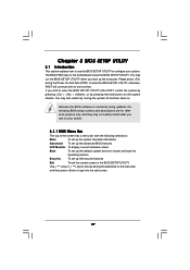
... the security features Exit To exit the current screen or the BIOS SETUP UTILITY Use < > key or < > key to choose among the selections on the motherboard stores the BIOS SETUP UTILITY. You may not exactly match what you wish to enter the BIOS SETUP UTILITY after POST, restart the system by...
... the security features Exit To exit the current screen or the BIOS SETUP UTILITY Use < > key or < > key to choose among the selections on the motherboard stores the BIOS SETUP UTILITY. You may not exactly match what you wish to enter the BIOS SETUP UTILITY after POST, restart the system by...

User Manual
Page 30
...to keep the CPU from the chipset. Enhance Halt State All processors support the Halt State (C1). Hyper Threading Technology To enable this motherboard. This should be hidden if the installed CPU does not support Intel (R) Virtualization Technology. CPU Thermal Throttling You may select [Enabled] ...to enable P4 CPU internal thermal control mechanism to boot legacy OSes that includes optimization for this motherboard. Set to enable power 30 Max CPUID Value Limit For Prescott CPU only, some OSes (ex. Ratio Actual Value This is a read...
...to keep the CPU from the chipset. Enhance Halt State All processors support the Halt State (C1). Hyper Threading Technology To enable this motherboard. This should be hidden if the installed CPU does not support Intel (R) Virtualization Technology. CPU Thermal Throttling You may select [Enabled] ...to enable P4 CPU internal thermal control mechanism to boot legacy OSes that includes optimization for this motherboard. Set to enable power 30 Max CPUID Value Limit For Prescott CPU only, some OSes (ex. Ratio Actual Value This is a read...
User Manual
Page 31
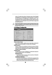
... [Auto] DRAM RAS# to CAS# Delay [Auto] DRAM RAS# Precharge [Auto] DRAM RAS# Activate to [Enabled]. DRAM CAS# Latency Use this option is selected, the motherboard will detect the memory module(s) inserted and assigns appropriate frequency automatically. The default value is [Disabled]. Please set to Precha [Auto] Primary Graphics Adapter [PCI...
... [Auto] DRAM RAS# to CAS# Delay [Auto] DRAM RAS# Precharge [Auto] DRAM RAS# Activate to [Enabled]. DRAM CAS# Latency Use this option is selected, the motherboard will detect the memory module(s) inserted and assigns appropriate frequency automatically. The default value is [Disabled]. Please set to Precha [Auto] Primary Graphics Adapter [PCI...

