
User Guide
Page 3
... You Begin 3 Obtaining Optional Components 3 Installing the NJ225 6 Checking the LEDs 13 About the NJ225FX 14 Before You Begin 15 Obtaining Optional Components 15 Installing the NJ225FX 15 Checking the LEDs 19 ... Advanced Options 33 Changing the Password Configuring for SNMP USING THE CENTRAL CONFIGURATION MANAGER Discovering IntelliJacks on Your Network 35 Viewing Device Properties 39 General Tab 40 Network Identification Port Information Product Information Hardware Settings Tab 42 Switch Status Power Status Statistics & Log Tab 45 General Counters RMON Counters Saving to a ...
... You Begin 3 Obtaining Optional Components 3 Installing the NJ225 6 Checking the LEDs 13 About the NJ225FX 14 Before You Begin 15 Obtaining Optional Components 15 Installing the NJ225FX 15 Checking the LEDs 19 ... Advanced Options 33 Changing the Password Configuring for SNMP USING THE CENTRAL CONFIGURATION MANAGER Discovering IntelliJacks on Your Network 35 Viewing Device Properties 39 General Tab 40 Network Identification Port Information Product Information Hardware Settings Tab 42 Switch Status Power Status Statistics & Log Tab 45 General Counters RMON Counters Saving to a ...

User Guide
Page 4
... Configuration (Flow Control, AutoMDI(X), Data Rate Control) Restoring to Base Configurations 61 Finding Computers Connected to IntelliJacks 64 Upgrading the NJ225 Firmware 65 Viewing Log Files 68 Viewing and Canceling Scheduled Firmware Upgrades 69 TROUBLESHOOTING THE NJ225 Troubleshooting Matrix 71 TECHNICAL SUPPORT Where To Go For Help 73 Contact Us 74 PRODUCT SPECIFICATIONS...
... Configuration (Flow Control, AutoMDI(X), Data Rate Control) Restoring to Base Configurations 61 Finding Computers Connected to IntelliJacks 64 Upgrading the NJ225 Firmware 65 Viewing Log Files 68 Viewing and Canceling Scheduled Firmware Upgrades 69 TROUBLESHOOTING THE NJ225 Troubleshooting Matrix 71 TECHNICAL SUPPORT Where To Go For Help 73 Contact Us 74 PRODUCT SPECIFICATIONS...

User Guide
Page 5
... wall outlet or data port opening. The NJ225 is IEEE 802.3af-compatible. Power to the IntelliJack is provided through the same NJ225. Consult the 3Com web site for more information. The NJ225 can also use a supported SNMP management console as in-line power, is a 4-port, managed Ethernet switch that supports Power Over Ethernet • Over...
... wall outlet or data port opening. The NJ225 is IEEE 802.3af-compatible. Power to the IntelliJack is provided through the same NJ225. Consult the 3Com web site for more information. The NJ225 can also use a supported SNMP management console as in-line power, is a 4-port, managed Ethernet switch that supports Power Over Ethernet • Over...

User Guide
Page 6
... socket The NJ225 can be powered...IntelliJack: 1 RJ-45 switched PAN Four 10/100 Mbps auto-negotiation ports, which the NJ225 (personal area configures for purchase from and unaffected by the NJ225 switch. 6 Power-forwarding LED Lights when the IntelliJack... is connected to-and forwarding power to your network does not support Power Over Ethernet (PoE). 2 CHAPTER 1: INSTALLING THE INTELLIJACK About the NJ225...NJ225 IntelliJack. For more information, see "Checking the LEDs" on page 13. 4 Power LED Indicates NJ225...
... socket The NJ225 can be powered...IntelliJack: 1 RJ-45 switched PAN Four 10/100 Mbps auto-negotiation ports, which the NJ225 (personal area configures for purchase from and unaffected by the NJ225 switch. 6 Power-forwarding LED Lights when the IntelliJack... is connected to-and forwarding power to your network does not support Power Over Ethernet (PoE). 2 CHAPTER 1: INSTALLING THE INTELLIJACK About the NJ225...NJ225 IntelliJack. For more information, see "Checking the LEDs" on page 13. 4 Power LED Indicates NJ225...
User Guide
Page 7
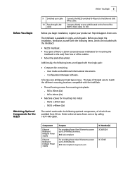
... mounting into metal: n M3.5 x 30mm (2x) n M3.5 x 40mm (2x) The switch works with the following items, which are shipped with the IntelliJack: • NJ225 IntelliJack. • Four pairs of the NJ225.) Black cable, no LED. Before you begin installation, register your LAN (located on the front ...http://eSupport.3com.com. and 20-packs. n Configuration Manager software. White cable. Before You Begin 3 Before You Begin Obtaining Optional Components for the NJ225 9 Switched port cable 10 Pass-through LAN cable Connects the NJ225 switched RJ-45ports to your product at www.3com.com or...
... mounting into metal: n M3.5 x 30mm (2x) n M3.5 x 40mm (2x) The switch works with the following items, which are shipped with the IntelliJack: • NJ225 IntelliJack. • Four pairs of the NJ225.) Black cable, no LED. Before you begin installation, register your LAN (located on the front ...http://eSupport.3com.com. and 20-packs. n Configuration Manager software. White cable. Before You Begin 3 Before You Begin Obtaining Optional Components for the NJ225 9 Switched port cable 10 Pass-through LAN cable Connects the NJ225 switched RJ-45ports to your product at www.3com.com or...
User Guide
Page 8
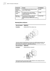
... 802.3af compliant PSE. 3CNJVOIP-NBX Mounting Plates and Spacers 3Com Part Number: 3CNJMP-EXT Description: IntelliJack NJ225 10mm extension ring 10mm-thick extension ring that attaches to securely install an NJ225 IntelliJack in wall openings with every unit, effectively extending the depth of an NJ225 IntelliJack extension ring that ships with built-in trim rings, as...
... 802.3af compliant PSE. 3CNJVOIP-NBX Mounting Plates and Spacers 3Com Part Number: 3CNJMP-EXT Description: IntelliJack NJ225 10mm extension ring 10mm-thick extension ring that attaches to securely install an NJ225 IntelliJack in wall openings with every unit, effectively extending the depth of an NJ225 IntelliJack extension ring that ships with built-in trim rings, as...
User Guide
Page 9
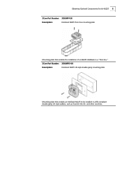
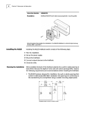
Obtaining Optional Components for the NJ225 5 3Com Part Number: 3CNJMP-FLR Description: IntelliJack NJ225 floor box mounting plate Mounting plate that enables the installation of an NJ225 IntelliJack in a "floor box." 3Com Part Number: 3CNJMPD-UK Description: IntelliJack NJ225 UK-style double gang mounting plate Mounting plate that enables an IntelliJack NJ225 to be installed in a BSI-compliant double-gang UK style wallbox, such as found in the UK and other countries.
Obtaining Optional Components for the NJ225 5 3Com Part Number: 3CNJMP-FLR Description: IntelliJack NJ225 floor box mounting plate Mounting plate that enables the installation of an NJ225 IntelliJack in a "floor box." 3Com Part Number: 3CNJMPD-UK Description: IntelliJack NJ225 UK-style double gang mounting plate Mounting plate that enables an IntelliJack NJ225 to be installed in a BSI-compliant double-gang UK style wallbox, such as found in the UK and other countries.
User Guide
Page 10
...NJ225 Installing the NJ225 IntelliJack switch consists of an NJ225 IntelliJack in a French-style raceway (locally called "goulotte"). Because the depth of the IntelliJack extends into a wall or cubicle opening at least 25mm. Installation into wall or cubicle openings that enables the installation of the following requirements and recommendations before installing the IntelliJack: • The NJ225... mounting adapter plate. 6 CHAPTER 1: INSTALLING THE INTELLIJACK 3Com Part Number: 3CNJMP-FR Description: IntelliJack NJ225 French-style raceway (goulotte) mounting plate Mounting plate...
...NJ225 Installing the NJ225 IntelliJack switch consists of an NJ225 IntelliJack in a French-style raceway (locally called "goulotte"). Because the depth of the IntelliJack extends into a wall or cubicle opening at least 25mm. Installation into wall or cubicle openings that enables the installation of the following requirements and recommendations before installing the IntelliJack: • The NJ225... mounting adapter plate. 6 CHAPTER 1: INSTALLING THE INTELLIJACK 3Com Part Number: 3CNJMP-FR Description: IntelliJack NJ225 French-style raceway (goulotte) mounting plate Mounting plate...

User Guide
Page 11
... the cable. NOTE: It is IEEE 802.3af-compliant. The NJ225 is ideally powered by some after -market faceplates. The NJ225 can be powered by a switch that is recommended that a professional cable installer perform these general guidelines. Consult the 3Com web site for the IntelliJack. In such cases, it is at your site (from the...
... the cable. NOTE: It is IEEE 802.3af-compliant. The NJ225 is ideally powered by some after -market faceplates. The NJ225 can be powered by a switch that is recommended that a professional cable installer perform these general guidelines. Consult the 3Com web site for the IntelliJack. In such cases, it is at your site (from the...

User Guide
Page 12
...to your network, as shown in the following illustration. Using an Integrated Switch with standard Category 5 or better cabling, and powers up to 24 IntelliJack devices. The Ethernet multi-port midspan power supply from 3Com connects to an existing Ethernet or Fast Ethernet infrastructure with Power Over ...Ethernet To use an Ethernet multi-port midspan power supply, you must have a switch on the IntelliJack, but it . CAUTION: Use only a power supply that is provided or approved by 3Com for use . Failure to do so may result in a hazardous situation or personal injury. ...
...to your network, as shown in the following illustration. Using an Integrated Switch with standard Category 5 or better cabling, and powers up to 24 IntelliJack devices. The Ethernet multi-port midspan power supply from 3Com connects to an existing Ethernet or Fast Ethernet infrastructure with Power Over ...Ethernet To use an Ethernet multi-port midspan power supply, you must have a switch on the IntelliJack, but it . CAUTION: Use only a power supply that is provided or approved by 3Com for use . Failure to do so may result in a hazardous situation or personal injury. ...

User Guide
Page 13
...it will not provide power to the IntelliJack. The black cable should be connected to an Ethernet multi-port midspan power supply and will power an IEEE 802.3af device connected to the pass-through port on the wire closet switch. Installing the NJ225 9 Connect the network second data/voice.../power cable (if available) to the IntelliJack black cable, as shown in the following illustration. Using a Single-port Ethernet Power Supply To ...
...it will not provide power to the IntelliJack. The black cable should be connected to an Ethernet multi-port midspan power supply and will power an IEEE 802.3af device connected to the pass-through port on the wire closet switch. Installing the NJ225 9 Connect the network second data/voice.../power cable (if available) to the IntelliJack black cable, as shown in the following illustration. Using a Single-port Ethernet Power Supply To ...

User Guide
Page 14
...-port or multi-port endspan power supply, you have an electrical outlet near the site where the IntelliJack will be installed. CAUTION: Use only a power supply that the cable is provided or approved by 3Com for use with a local power supply, make sure you must purchase a local power supply from top... to bottom. 5 Secure the local power supply and cable to the IntelliJack, or may result in damage to the wall. 6 Plug the local...
...-port or multi-port endspan power supply, you have an electrical outlet near the site where the IntelliJack will be installed. CAUTION: Use only a power supply that the cable is provided or approved by 3Com for use with a local power supply, make sure you must purchase a local power supply from top... to bottom. 5 Secure the local power supply and cable to the IntelliJack, or may result in damage to the wall. 6 Plug the local...
User Guide
Page 15
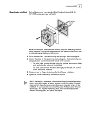
... outlet box. 4 Tighten the screws while holding the IntelliJack in place. The IntelliJack has two Category 5 cables each terminated with a male RJ-45 connector. Before connecting the IntelliJack to place the 3Com spacer between the IntelliJack and the after -market faceplates stand out from the...wiring closet is connected to the single pass-through port located on the front of the IntelliJack. 3 Choose one pair of the IntelliJack. Installing the NJ225 11 Mounting the IntelliJack The IntelliJack mounts in any standard British Standard Institute (BSI): BS 4664:1970 cubicle opening in the...
... outlet box. 4 Tighten the screws while holding the IntelliJack in place. The IntelliJack has two Category 5 cables each terminated with a male RJ-45 connector. Before connecting the IntelliJack to place the 3Com spacer between the IntelliJack and the after -market faceplates stand out from the...wiring closet is connected to the single pass-through port located on the front of the IntelliJack. 3 Choose one pair of the IntelliJack. Installing the NJ225 11 Mounting the IntelliJack The IntelliJack mounts in any standard British Standard Institute (BSI): BS 4664:1970 cubicle opening in the...

User Guide
Page 16
... data or voice traffic that allows an additional device to be connected to a separate network segment through the IntelliJack without being switched. All ports feature 10/100 Mbps auto-negotiation, which configures the NJ225 IntelliJack for 10 Mbps or 100 Mbps connections automatically. 2 Pass-through port-a single pass-through port is provided that travels...
... data or voice traffic that allows an additional device to be connected to a separate network segment through the IntelliJack without being switched. All ports feature 10/100 Mbps auto-negotiation, which configures the NJ225 IntelliJack for 10 Mbps or 100 Mbps connections automatically. 2 Pass-through port-a single pass-through port is provided that travels...

User Guide
Page 17
...LED light blinks once or twice before remaining solid on. n Off-the IntelliJack is not connected to and is a delay of approximately 5 seconds. n Off-the IntelliJack is not receiving power. (Power-forwarding) n On-the IntelliJack is connected to or is receiving power (local or via the network)....link has been established. CAUTION: Make sure the wiring closet port connected to the IntelliJack white cable is connected to an IEEE 802.3af-compliant device. Checking the LEDs Checking the LEDs 13 You can verify the NJ225 installation by checking the LEDs. LED Description n On-the...
...LED light blinks once or twice before remaining solid on. n Off-the IntelliJack is not connected to and is a delay of approximately 5 seconds. n Off-the IntelliJack is not receiving power. (Power-forwarding) n On-the IntelliJack is connected to or is receiving power (local or via the network)....link has been established. CAUTION: Make sure the wiring closet port connected to the IntelliJack white cable is connected to an IEEE 802.3af-compliant device. Checking the LEDs Checking the LEDs 13 You can verify the NJ225 installation by checking the LEDs. LED Description n On-the...

User Guide
Page 18
The following diagram shows the front, rear, and bottom views of the NJ225FX: Figure 1 NJ225FX-ST Figure 2 NJ225FX-SC 14 CHAPTER 1: INSTALLING THE INTELLIJACK About the NJ225FX The 3Com IntelliJack NJ225FX is no additional pass-through port and the NJ225FX cannot be managed by the same software that it has a fiber uplink to the NJ225, except that the NJ225 uses. The main differences are that the LAN port cannot be configured, there is similar to the network. It ships with and can be powered via Power over Ethernet (PoE).
The following diagram shows the front, rear, and bottom views of the NJ225FX: Figure 1 NJ225FX-ST Figure 2 NJ225FX-SC 14 CHAPTER 1: INSTALLING THE INTELLIJACK About the NJ225FX The 3Com IntelliJack NJ225FX is no additional pass-through port and the NJ225FX cannot be managed by the same software that it has a fiber uplink to the NJ225, except that the NJ225 uses. The main differences are that the LAN port cannot be configured, there is similar to the network. It ships with and can be powered via Power over Ethernet (PoE).
User Guide
Page 19
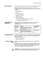
...3com.com or by an IEEE 802.3af compliant PSE. 3CNJVOIP-NBX Installing the NJ225FX Due to hardware differences, installing the NJ225FX requires a slightly different procedure than the NJ225. The connector can accept 100~240V AC power if you have access to AC power near the unit. The switch works with the IntelliJack...: • NJ225FX IntelliJack. • Trim ring • Two mounting ...
...3com.com or by an IEEE 802.3af compliant PSE. 3CNJVOIP-NBX Installing the NJ225FX Due to hardware differences, installing the NJ225FX requires a slightly different procedure than the NJ225. The connector can accept 100~240V AC power if you have access to AC power near the unit. The switch works with the IntelliJack...: • NJ225FX IntelliJack. • Trim ring • Two mounting ...

User Guide
Page 20
...can be damaged otherwise. 2 Directly via DC power: For DC power, a 3Com local power supply (3CNJPSL sold separately), can plug directly into a standard power outlet. Mounting the NJ225FX Before connecting the IntelliJack to the network, verify that will best suit your needs. The unit may ...be plugged directly into the 225FX. The IntelliJack includes mounting brackets designed to an active fiber port. 16 CHAPTER 1: ...
...can be damaged otherwise. 2 Directly via DC power: For DC power, a 3Com local power supply (3CNJPSL sold separately), can plug directly into a standard power outlet. Mounting the NJ225FX Before connecting the IntelliJack to the network, verify that will best suit your needs. The unit may ...be plugged directly into the 225FX. The IntelliJack includes mounting brackets designed to an active fiber port. 16 CHAPTER 1: ...

User Guide
Page 21
If using DC, plug the cord into the green connector. Connect AC or DC power to unit. 4 Connect fiber cables to the raceway while holding the IntelliJack unit in place. If using AC, screw the power wires into a power outlet. Raceways Installing the NJ225FX 17 Instructions for Tehalit BR70130 and BRN70110/1 (may work with other designs): 1 Attach clamp assembly to the raceway. 2 Place 225FX into the raceway. 6 Tighten supplied screws to the fiber transceiver on the unit. 5 Mount the unit and trim ring into the trim ring. 3 Prepare the AC or DC power supply.
If using DC, plug the cord into the green connector. Connect AC or DC power to unit. 4 Connect fiber cables to the raceway while holding the IntelliJack unit in place. If using AC, screw the power wires into a power outlet. Raceways Installing the NJ225FX 17 Instructions for Tehalit BR70130 and BRN70110/1 (may work with other designs): 1 Attach clamp assembly to the raceway. 2 Place 225FX into the raceway. 6 Tighten supplied screws to the fiber transceiver on the unit. 5 Mount the unit and trim ring into the trim ring. 3 Prepare the AC or DC power supply.

User Guide
Page 22
18 CHAPTER 1: INSTALLING THE INTELLIJACK Instructions for Tehalit BRSN70170/1 (may work with other designs): 1 Snap plastic mounting box into raceway. 2 Repeat steps 2 through 6 as above. Floor Boxes
18 CHAPTER 1: INSTALLING THE INTELLIJACK Instructions for Tehalit BRSN70170/1 (may work with other designs): 1 Snap plastic mounting box into raceway. 2 Repeat steps 2 through 6 as above. Floor Boxes