Getting Started Guide
Page 3
CONTENTS ABOUT THIS GUIDE Conventions 5 Related Documentation 5 1 PRODUCT OVERVIEW Introduction 7 Switch 4800G 24-Port 8 Switch 4800G PWR 48-Port 11 Switch 4800G PWR 24-Port 13 Switch 4800G 24-Port SFP 17 Switch 4800G 48-Port 18 System Specifications of the Switch 4800G Series 22 Pluggable Modules 22 Optional Interface Modules 23 CX4 Cable 24 2 PREPARATING TO INSTALL THE SWITCH Safety Precautions 25 Installation Site 25 Installation Tools 27 3 INSTALLING THE...
CONTENTS ABOUT THIS GUIDE Conventions 5 Related Documentation 5 1 PRODUCT OVERVIEW Introduction 7 Switch 4800G 24-Port 8 Switch 4800G PWR 48-Port 11 Switch 4800G PWR 24-Port 13 Switch 4800G 24-Port SFP 17 Switch 4800G 48-Port 18 System Specifications of the Switch 4800G Series 22 Pluggable Modules 22 Optional Interface Modules 23 CX4 Cable 24 2 PREPARATING TO INSTALL THE SWITCH Safety Precautions 25 Installation Site 25 Installation Tools 27 3 INSTALLING THE...
Getting Started Guide
Page 7
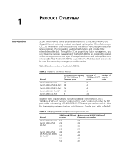
... (MANs). The Switch 4800G are Gigabit Ethernet switching products developed by Hangzhou 3Com Technologies Co., Ltd. (hereinafter referred to Table 3. 1 PRODUCT OVERVIEW Introduction 3Com Switch 4800G Family (hereinafter referred to as the Switch 4800G) are designed to operate at a time. For the mapping between two ports forming a Combo port Model Switch 4800G 24-Port Switch 4800G PWR 24-Port Switch 4800G PWR 48-Port Switch 4800G 24-Port SFP 1000Base-X SFP port Auto-sensing 10...
... (MANs). The Switch 4800G are Gigabit Ethernet switching products developed by Hangzhou 3Com Technologies Co., Ltd. (hereinafter referred to Table 3. 1 PRODUCT OVERVIEW Introduction 3Com Switch 4800G Family (hereinafter referred to as the Switch 4800G) are designed to operate at a time. For the mapping between two ports forming a Combo port Model Switch 4800G 24-Port Switch 4800G PWR 24-Port Switch 4800G PWR 48-Port Switch 4800G 24-Port SFP 1000Base-X SFP port Auto-sensing 10...
Getting Started Guide
Page 8
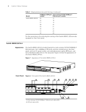
... their front panel. Figure 2 shows the appearance of the Switch 4800G 24-Port (1) (2) (3) (4) (5) (6) (7) (8) (10) (9) (1) Auto-sensing 10/100/1000Base-T Ethernet port status LEDs (2) SFP port status LEDs 8 CHAPTER 1: PRODUCT OVERVIEW Table 3 Mapping between two ports forming a Combo port Model Switch 4800G 48-Port 1000Base-X SFP port Auto-sensing 10/100/1000Base-T number Ethernet port number 25 17 26 18 27 19 28 20...
... their front panel. Figure 2 shows the appearance of the Switch 4800G 24-Port (1) (2) (3) (4) (5) (6) (7) (8) (10) (9) (1) Auto-sensing 10/100/1000Base-T Ethernet port status LEDs (2) SFP port status LEDs 8 CHAPTER 1: PRODUCT OVERVIEW Table 3 Mapping between two ports forming a Combo port Model Switch 4800G 48-Port 1000Base-X SFP port Auto-sensing 10/100/1000Base-T number Ethernet port number 25 17 26 18 27 19 28 20...
Getting Started Guide
Page 11
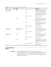
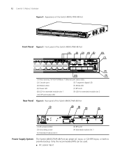
...LED flashes at a high frequency. The port fails the POST. When data is present. Switch 4800G PWR 48-Port Appearance The Switch 4800G PWR 48-Port provides forty-eight auto-sensing 10/100/1000BASE-T Ethernet ports, four 1000Base-X SFP ports, and one console port on the front panel, and one ...Figure 5 shows the appearance of the Switch 4800G 24-Port LED 10/100/1000Base-T port status LED Mark Status - No link is present. No link is present. Switch 4800G PWR 48-Port 11 Table 4 LEDs on the front panel of the Switch 4800G PWR 48-Port. Speed Green Yellow Duplex Flashing yellow...
...LED flashes at a high frequency. The port fails the POST. When data is present. Switch 4800G PWR 48-Port Appearance The Switch 4800G PWR 48-Port provides forty-eight auto-sensing 10/100/1000BASE-T Ethernet ports, four 1000Base-X SFP ports, and one console port on the front panel, and one ...Figure 5 shows the appearance of the Switch 4800G 24-Port LED 10/100/1000Base-T port status LED Mark Status - No link is present. No link is present. Switch 4800G PWR 48-Port 11 Table 4 LEDs on the front panel of the Switch 4800G PWR 48-Port. Speed Green Yellow Duplex Flashing yellow...
Getting Started Guide
Page 12
... for extended module slot 1 (9) LED for extended module slot 2 (10) SFP port status LED Rear Panel Figure 6 Rear panel of the Switch 4800G PWR 48-Port (1) (2) (3) (4) (5) (1) AC power socket (3) Grounding screw (5) Extended module slot 2 (2) RPS port (4) Extended module slot 1 Power Supply System The Switch 4800G PWR 48-Port can be used. ■ AC power input Only the recommended RPS can...
... for extended module slot 1 (9) LED for extended module slot 2 (10) SFP port status LED Rear Panel Figure 6 Rear panel of the Switch 4800G PWR 48-Port (1) (2) (3) (4) (5) (1) AC power socket (3) Grounding screw (5) Extended module slot 2 (2) RPS port (4) Extended module slot 1 Power Supply System The Switch 4800G PWR 48-Port can be used. ■ AC power input Only the recommended RPS can...
Getting Started Guide
Page 13
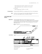
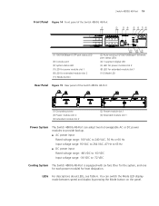
... of the Switch 4800G PWR 48-Port are the same as those of the Switch 4800G PWR 24-Port (1) (2) (3) (4) (5) (6) (7) (8) (10) (9) (1) Auto-sensing 10/100/1000Base-T Ethernet port status LEDs (2) SFP port status LED (3) Console port (4) 7-segment digital LED (5) Power LED (6) RPS LED Figure 7 Appearance of the Switch 4800G PWR 24-Port Front Panel Figure 8 Front panel of the Switch 4800G 24-Port. Switch 4800G PWR 24-Port 13 Rated...
... of the Switch 4800G PWR 48-Port are the same as those of the Switch 4800G PWR 24-Port (1) (2) (3) (4) (5) (6) (7) (8) (10) (9) (1) Auto-sensing 10/100/1000Base-T Ethernet port status LEDs (2) SFP port status LED (3) Console port (4) 7-segment digital LED (5) Power LED (6) RPS LED Figure 7 Appearance of the Switch 4800G PWR 24-Port Front Panel Figure 8 Front panel of the Switch 4800G 24-Port. Switch 4800G PWR 24-Port 13 Rated...
Getting Started Guide
Page 18
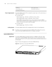
..., 47 Hz or 63 Hz Only the RPS recommended by 3Com can be damaged. ■ DC power input Rated voltage range: -52 VDC to -55 VDC Cooling System The Switch 4800G 24-Port SFP is equipped with six fans for the Switch 4800G 24-Port SFP. The -48 VDC power supply in the equipment room cannot be used...
..., 47 Hz or 63 Hz Only the RPS recommended by 3Com can be damaged. ■ DC power input Rated voltage range: -52 VDC to -55 VDC Cooling System The Switch 4800G 24-Port SFP is equipped with six fans for the Switch 4800G 24-Port SFP. The -48 VDC power supply in the equipment room cannot be used...
Getting Started Guide
Page 19
... equipped with six fans (four for the system, and one for each power module) for heat dissipation. Switch 4800G 48-Port 19 Front Panel Figure 14 Front panel of the Switch 4800G 48-Port (1) (2) (3) (4) (5) (6) (7) (8) (1) 100/1000Base-X SFP port status LED (3) Console port (5) System status LED (7) LED for power module slot 1 (9) LED for extended module slot 2 (11) Mode button (11) (10...
... equipped with six fans (four for the system, and one for each power module) for heat dissipation. Switch 4800G 48-Port 19 Front Panel Figure 14 Front panel of the Switch 4800G 48-Port (1) (2) (3) (4) (5) (6) (7) (8) (1) 100/1000Base-X SFP port status LED (3) Console port (5) System status LED (7) LED for power module slot 1 (9) LED for extended module slot 2 (11) Mode button (11) (10...
Getting Started Guide
Page 20
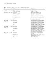
...position and works normally. No module is normal. 20 CHAPTER 1: PRODUCT OVERVIEW Table 6 Description of LEDs on the front panel of the Switch 4800G 48-Port LED Mode LED System power LED Mark Status Mode Speed Solid green Duplex Solid yellow SYS Solid green Flashing green (1 Hz) Solid red ... slot 2 PWR2 Solid green Solid yellow OFF Module LED MOD Solid green Flashing yellow OFF Description Rate of the port Duplex of the port The switch is running a POST. The switch does not support the module or a module failure occurs. The system is started normally. The system fails the ...
...position and works normally. No module is normal. 20 CHAPTER 1: PRODUCT OVERVIEW Table 6 Description of LEDs on the front panel of the Switch 4800G 48-Port LED Mode LED System power LED Mark Status Mode Speed Solid green Duplex Solid yellow SYS Solid green Flashing green (1 Hz) Solid red ... slot 2 PWR2 Solid green Solid yellow OFF Module LED MOD Solid green Flashing yellow OFF Description Rate of the port Duplex of the port The switch is running a POST. The switch does not support the module or a module failure occurs. The system is started normally. The system fails the ...
Getting Started Guide
Page 21
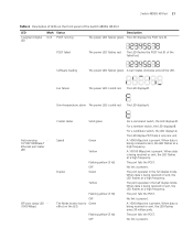
... loading The power LED flashes green. The LED displays t. The port operates in the half duplex mode. The port operates in the full duplex mode. The LED flashes the POST test ID of the Switch 4800G 48-Port LED 7-segment digital LED Mark Status Unit POST running Description The ...rotates clockwise around the LED. When data is being received or sent, the LED flashes at a high frequency. The port fails the POST. A 1000 Mbps link is present. Switch 4800G 48-Port 21 Table 6 Description of LEDs on the LED. The LED displays 1 if there is present. When data is...
... loading The power LED flashes green. The LED displays t. The port operates in the half duplex mode. The port operates in the full duplex mode. The LED flashes the POST test ID of the Switch 4800G 48-Port LED 7-segment digital LED Mark Status Unit POST running Description The ...rotates clockwise around the LED. When data is being received or sent, the LED flashes at a high frequency. The port fails the POST. A 1000 Mbps link is present. Switch 4800G 48-Port 21 Table 6 Description of LEDs on the LED. The LED displays 1 if there is present. When data is...
Getting Started Guide
Page 22
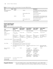
... the POST. 22 CHAPTER 1: PRODUCT OVERVIEW Table 6 Description of LEDs on the front panel of the Switch 4800G Item Switch 4800G 24-Port Switch 4800G PWR 48-Port Switch 4800G PWR 24-Port Switch 4800G 24-Port SFP Switch 4800G 48-Port Physical dimensions (H × W × D) 43.6 × 440 × 300 mm (1.72 × 17.3 × 11.8 in.) 43.6 × 440 × 420 mm (1.72 × 17.3 &#...
... the POST. 22 CHAPTER 1: PRODUCT OVERVIEW Table 6 Description of LEDs on the front panel of the Switch 4800G Item Switch 4800G 24-Port Switch 4800G PWR 48-Port Switch 4800G PWR 24-Port Switch 4800G 24-Port SFP Switch 4800G 48-Port Physical dimensions (H × W × D) 43.6 × 440 × 300 mm (1.72 × 17.3 × 11.8 in.) 43.6 × 440 × 420 mm (1.72 × 17.3 &#...
Getting Started Guide
Page 23
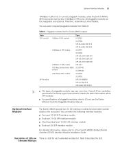
... SFP interface module For detailed information, please refer to connect pluggable modules, while the Switch 4800G 48-Port provides twenty-four 1000Base-X SFP ports. Consult 3Com marketing personnel or technical support personnel to 3Com Low End Series Ethernet Switches Pluggable Modules Manual. All pluggable modules are hot swappable and optional. You can select required pluggable modules from Table...
... SFP interface module For detailed information, please refer to connect pluggable modules, while the Switch 4800G 48-Port provides twenty-four 1000Base-X SFP ports. Consult 3Com marketing personnel or technical support personnel to 3Com Low End Series Ethernet Switches Pluggable Modules Manual. All pluggable modules are hot swappable and optional. You can select required pluggable modules from Table...
Getting Started Guide
Page 30
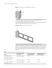
... of a standard front mounting ear (1) (2) (1) Screw hole used to fix the switch to the physical dimensions. Table 13 Selection of mounting ear for the Switch 4800G Model Switch 4800G 24-Port Switch 4800G 24-Port-DC Switch 4800G PWR 48-Port Switch 4800G 48-Port Switch 4800G PWR 24-Port Switch 4800G 24-Port SFP Physical dimensions (H × W × D) 43.6 × 440 &#... (2) Screw hole used to fix the mounting ear to the cabinet (Use one M6 screw) When you install the switch into a 19-inch standard cabinet, you should select front and rear mounting ears with a proper length (L1 in ...
... of a standard front mounting ear (1) (2) (1) Screw hole used to fix the switch to the physical dimensions. Table 13 Selection of mounting ear for the Switch 4800G Model Switch 4800G 24-Port Switch 4800G 24-Port-DC Switch 4800G PWR 48-Port Switch 4800G 48-Port Switch 4800G PWR 24-Port Switch 4800G 24-Port SFP Physical dimensions (H × W × D) 43.6 × 440 &#... (2) Screw hole used to fix the mounting ear to the cabinet (Use one M6 screw) When you install the switch into a 19-inch standard cabinet, you should select front and rear mounting ears with a proper length (L1 in ...

Getting Started Guide
Page 33
...positions on both sides of the switch with the other hand, and push the switch into the cabinet gently, as shown in Figure 24. You should select a proper position according to the rear brackets with one hand and the front part of the Switch 4800G 48-Port). Figure 23 Fix rear mounting ears... Rear mounting ears Rear square-holed bracket 5 Hold the bottom of the switch with screws and captive nuts, as shown in Figure 23. The rear mounting ears ...
...positions on both sides of the switch with the other hand, and push the switch into the cabinet gently, as shown in Figure 24. You should select a proper position according to the rear brackets with one hand and the front part of the Switch 4800G 48-Port). Figure 23 Fix rear mounting ears... Rear mounting ears Rear square-holed bracket 5 Hold the bottom of the switch with screws and captive nuts, as shown in Figure 23. The rear mounting ears ...
Getting Started Guide
Page 39
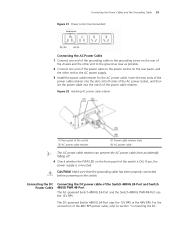
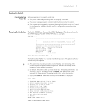
... of the 48V RPS power cable, refer to the AC power supply. 3 Install the power cable retainer for the AC power cable. The DC-powered Switch 4800G 24-Port uses the 12V RPS or the 48V RPS. Figure 32 Installing AC power cable retainer (1) Rear panel of the... slots at both sides of the AC power socket, and then set the power cable into the notch of the Switch 4800G 24-Port and Switch 4800G PWR 48-Port The AC-powered Switch 4800G 24-Port and the Switch 4800G PWR 48-Port use the 12V RPS. Connecting the DC Power Cable Connecting the DC power cable of the power cable retainer. Connecting...
... of the 48V RPS power cable, refer to the AC power supply. 3 Install the power cable retainer for the AC power cable. The DC-powered Switch 4800G 24-Port uses the 12V RPS or the 48V RPS. Figure 32 Installing AC power cable retainer (1) Rear panel of the... slots at both sides of the AC power socket, and then set the power cable into the notch of the Switch 4800G 24-Port and Switch 4800G PWR 48-Port The AC-powered Switch 4800G 24-Port and the Switch 4800G PWR 48-Port use the 12V RPS. Connecting the DC Power Cable Connecting the DC power cable of the power cable retainer. Connecting...

Getting Started Guide
Page 40
40 CHAPTER 3: INSTALLING THE SWITCH power cable of the grounding cable to the grounding screw on page 43. Figure 33 Appearance of the 12V RPS socket Pin Number 1 2 3 4 5 6 7 Designation GND -... 12 13 14 Designation GND -50V RPS_pres -50Vrtn -50Vrtn Control Pin GND Connect the DC power cable of the Switch 4800G 24-Port and Switch 4800G PWR 48-Port as follows: 1 Connect one end of the Switch 4800G 48-Port and Switch 4800G 24-Port-DC" on the rear panel and the other end to the ground as near as possible. 2 Connect the 12V...
40 CHAPTER 3: INSTALLING THE SWITCH power cable of the grounding cable to the grounding screw on page 43. Figure 33 Appearance of the 12V RPS socket Pin Number 1 2 3 4 5 6 7 Designation GND -... 12 13 14 Designation GND -50V RPS_pres -50Vrtn -50Vrtn Control Pin GND Connect the DC power cable of the Switch 4800G 24-Port and Switch 4800G PWR 48-Port as follows: 1 Connect one end of the Switch 4800G 48-Port and Switch 4800G 24-Port-DC" on the rear panel and the other end to the ground as near as possible. 2 Connect the 12V...

Getting Started Guide
Page 43
... use the 48V RPS, whose input voltage is in Figure 41. Connecting the DC power cable of the Switch 4800G 48-Port and Switch 4800G 24-Port-DC The Switch 4800G 48-Port and Switch 4800G 24-Port-DC use a small flat-module screwdriver to -60 V. Figure 41 Connect the 48V RPS connector to the chassis Screw 2 Connector parts Screw 1 Chassis 3 Check whether ...
... use the 48V RPS, whose input voltage is in Figure 41. Connecting the DC power cable of the Switch 4800G 48-Port and Switch 4800G 24-Port-DC The Switch 4800G 48-Port and Switch 4800G 24-Port-DC use a small flat-module screwdriver to -60 V. Figure 41 Connect the 48V RPS connector to the chassis Screw 2 Connector parts Screw 1 Chassis 3 Check whether ...
Getting Started Guide
Page 57
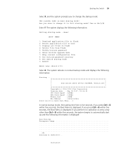
... self-test operations. ■ By default, the system starts up in flash 4. Modify bootrom password 6. Powering On the Switch The Switch 4800G have been set the startup mode to enter Boot Menu... 0 The last line asks whether you press Ctrl + B within...; The normal startup mode takes a little longer time than the fast startup mode because of Switch 4800G 48-Port as an example: Starting...... * * * 3Com Switch 4800G 48-Port BOOTROM, Version 205 * * * Copyright(c) 2004-2008 3Com Corporation. Select application file to flash 2. the terminal (which can be a PC) used ...
... self-test operations. ■ By default, the system starts up in flash 4. Modify bootrom password 6. Powering On the Switch The Switch 4800G have been set the startup mode to enter Boot Menu... 0 The last line asks whether you press Ctrl + B within...; The normal startup mode takes a little longer time than the fast startup mode because of Switch 4800G 48-Port as an example: Starting...... * * * 3Com Switch 4800G 48-Port BOOTROM, Version 205 * * * Copyright(c) 2004-2008 3Com Corporation. Select application file to flash 2. the terminal (which can be a PC) used ...
Getting Started Guide
Page 59
... bootrom password recovery 9. Reboot Enter your choice(0-9): Select 0. Download application file to full startup mode? The system displays the following information: Starting...... * * * 3Com Switch 4800G 48-Port BOOTROM, Version 205 * * * Copyright(c) 2004-2008 3Com Corporation. Creation date : May 28 2007, 15:36:08 CPU Clock Speed : 533MHz BUS Clock Speed : 133MHz Memory Size : 256MB Mac Address...
... bootrom password recovery 9. Reboot Enter your choice(0-9): Select 0. Download application file to full startup mode? The system displays the following information: Starting...... * * * 3Com Switch 4800G 48-Port BOOTROM, Version 205 * * * Copyright(c) 2004-2008 3Com Corporation. Creation date : May 28 2007, 15:36:08 CPU Clock Speed : 533MHz BUS Clock Speed : 133MHz Memory Size : 256MB Mac Address...
Getting Started Guide
Page 61
... version when you can be used for remote real-time loading. Creation date : May 28 2007, 15:36:08 Boot Menu Starting...... * * * 3Com Switch 4800G 48-Port BOOTROM, Version 205 * * * Copyright(c) 2004-2008 3Com Corporation. Introduction to do this remotely. To resolve these modules, the software and files can load Boot ROM and host software locally...
... version when you can be used for remote real-time loading. Creation date : May 28 2007, 15:36:08 Boot Menu Starting...... * * * 3Com Switch 4800G 48-Port BOOTROM, Version 205 * * * Copyright(c) 2004-2008 3Com Corporation. Introduction to do this remotely. To resolve these modules, the software and files can load Boot ROM and host software locally...

