Getting Started Guide
Page 4
... 42 Using 3Com Network Supervisor 42 Connecting to the Console Port 42 Methods of Managing a Switch 45 Command Line Interface Management 45 Web Interface Management 46 SNMP Management 46 Setting Up Command Line Interface Management 47 CLI Management via the Console Port 47 CLI Management over the Network 47 Setting Up Web Interface Management 48 Pre-requisites 48 Web Management Over the Network 49 Setting Up SNMP Management 49 Pre-requisites 50 Default Users and Passwords 50 Changing Default Passwords 50 4 PROBLEM SOLVING Solving Problems Indicated by LEDs 54 Solving Hardware Problems 55...
... 42 Using 3Com Network Supervisor 42 Connecting to the Console Port 42 Methods of Managing a Switch 45 Command Line Interface Management 45 Web Interface Management 46 SNMP Management 46 Setting Up Command Line Interface Management 47 CLI Management via the Console Port 47 CLI Management over the Network 47 Setting Up Web Interface Management 48 Pre-requisites 48 Web Management Over the Network 49 Setting Up SNMP Management 49 Pre-requisites 50 Default Users and Passwords 50 Changing Default Passwords 50 4 PROBLEM SOLVING Solving Problems Indicated by LEDs 54 Solving Hardware Problems 55...
Getting Started Guide
Page 12
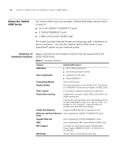
... supported by the Switch 4200 Series. You can also add the Switch 4200 Series to SuperStack Advanced Redundant Power System (ARPS) (3C16071, 3C16071A or 3C16071B) Mounting 19-inch rack or stand-alone mounting Smart auto-sensing allows auto-negotiating ports to monitor and detect a high error rate on a link, or a problem in the "physical" interconnection to 64 permanent entries Auto-negotiation ■ Supported on all ports ■ Auto MDI/MDI-X Forwarding Modes Store and Forward Duplex Modes Half and full duplex...
... supported by the Switch 4200 Series. You can also add the Switch 4200 Series to SuperStack Advanced Redundant Power System (ARPS) (3C16071, 3C16071A or 3C16071B) Mounting 19-inch rack or stand-alone mounting Smart auto-sensing allows auto-negotiating ports to monitor and detect a high error rate on a link, or a problem in the "physical" interconnection to 64 permanent entries Auto-negotiation ■ Supported on all ports ■ Auto MDI/MDI-X Forwarding Modes Store and Forward Duplex Modes Half and full duplex...
Getting Started Guide
Page 15
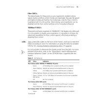
... negotiated with the Switch. Green / Yellow A 10 or 100 Mbps link is present, but the port is auto-negotiation enabled, where speed, duplex and flow control modes are being transmitted/received on the front of the Switch, and how to read their status according to determine the duplex mode from the LEDs. The default state for flow control support, effectively enabling or disabling flow control. About the Switch 4200 Series 15 Fiber GBIC's. Yellow flashing Packets are negotiated. Although...
... negotiated with the Switch. Green / Yellow A 10 or 100 Mbps link is present, but the port is auto-negotiation enabled, where speed, duplex and flow control modes are being transmitted/received on the front of the Switch, and how to read their status according to determine the duplex mode from the LEDs. The default state for flow control support, effectively enabling or disabling flow control. About the Switch 4200 Series 15 Fiber GBIC's. Yellow flashing Packets are negotiated. Although...
Getting Started Guide
Page 16
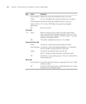
... Mbps link present but disabled. alternating Off No link is enabled. 16 CHAPTER 1: INTRODUCING THE SUPERSTACK 3 SWITCH 4200 SERIES LED Color Indicates Green flashing Packets are being transmitted/received on the port. Unit LED number 1 can also indicate a stand-alone Switch. Power/Self Test LED Green The Switch is present. Refer to flash. Unit LEDs 1-4 Green When the Switch forms a stack with the Power Supply Unit. Yellow flashing Packets are being transmitted/received on the port. Green flashing The Switch is either downloading software or...
... Mbps link present but disabled. alternating Off No link is enabled. 16 CHAPTER 1: INTRODUCING THE SUPERSTACK 3 SWITCH 4200 SERIES LED Color Indicates Green flashing Packets are being transmitted/received on the port. Unit LED number 1 can also indicate a stand-alone Switch. Power/Self Test LED Green The Switch is present. Refer to flash. Unit LEDs 1-4 Green When the Switch forms a stack with the Power Supply Unit. Yellow flashing Packets are being transmitted/received on the port. Green flashing The Switch is either downloading software or...
Getting Started Guide
Page 18
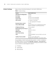
... other traffic. 18 CHAPTER 1: INTRODUCING THE SUPERSTACK 3 SWITCH 4200 SERIES Default Settings Table 5 shows the default settings for all ports RMON Alarm Enabled Smart Auto-Sensing Enabled LACP (10/100/1000BASE-T ports and GBIC ports only) Enabled Quality of Service (QoS) All ports prioritize NBX VoIP IP. All ports set to "best effort" for the Switch 4200 Series: Table 5 Default Settings Feature Switch 4200 Series Automatic IP Configuration Enabled Port Status Enabled Port Speed All ports are auto-negotiated Duplex Mode All ports are auto-negotiated Flow Control...
... other traffic. 18 CHAPTER 1: INTRODUCING THE SUPERSTACK 3 SWITCH 4200 SERIES Default Settings Table 5 shows the default settings for all ports RMON Alarm Enabled Smart Auto-Sensing Enabled LACP (10/100/1000BASE-T ports and GBIC ports only) Enabled Quality of Service (QoS) All ports prioritize NBX VoIP IP. All ports set to "best effort" for the Switch 4200 Series: Table 5 Default Settings Feature Switch 4200 Series Automatic IP Configuration Enabled Port Status Enabled Port Speed All ports are auto-negotiated Duplex Mode All ports are auto-negotiated Flow Control...
Getting Started Guide
Page 23
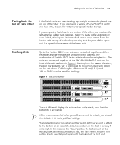
... top of the stack, the port marked with 'up' is connected to the port marked with 'down ' port on the bottom unit of SuperStack® 3 Switch and Hub units, the smaller units must use that port again until the link is lost on that when you add a new unit to a stack, you must be positioned at the top. 3Com recommends that port. Figure 6 Stacking example 1 25 2 26 3 27...
... top of the stack, the port marked with 'up' is connected to the port marked with 'down ' port on the bottom unit of SuperStack® 3 Switch and Hub units, the smaller units must use that port again until the link is lost on that when you add a new unit to a stack, you must be positioned at the top. 3Com recommends that port. Figure 6 Stacking example 1 25 2 26 3 27...

Getting Started Guide
Page 24
... Stack Formation Problems" on that your Switch is operating correctly. If you are disabled and the LEDs light in the stack to divide into two stacks. Switch 4200 Series 1 Plug the power cord into your Switch 4200 Series powered-up and ready for the LED. When the POST has completed, check the Power On Self Test LED to make sure that port. Table 6 shows possible colors for operation. Powering-up the Use...
... Stack Formation Problems" on that your Switch is operating correctly. If you are disabled and the LEDs light in the stack to divide into two stacks. Switch 4200 Series 1 Plug the power cord into your Switch 4200 Series powered-up and ready for the LED. When the POST has completed, check the Power On Self Test LED to make sure that port. Table 6 shows possible colors for operation. Powering-up the Use...

Getting Started Guide
Page 31
... different methods of Managing a Switch ■ Setting Up Command Line Interface Management ■ Setting Up Web Interface Management ■ Setting Up SNMP Management ■ Default Users and Passwords It covers the following topics: ■ Setting Up Overview ■ Manually Configuring IP Information ■ Viewing Automatically Configured IP Information ■ Methods of accessing the management software to manage a Switch. However, to change and monitor the way it will work straight away (plug-and-play). This is , you can install it and it...
... different methods of Managing a Switch ■ Setting Up Command Line Interface Management ■ Setting Up Web Interface Management ■ Setting Up SNMP Management ■ Default Users and Passwords It covers the following topics: ■ Setting Up Overview ■ Manually Configuring IP Information ■ Viewing Automatically Configured IP Information ■ Methods of accessing the management software to manage a Switch. However, to change and monitor the way it will work straight away (plug-and-play). This is , you can install it and it...

Getting Started Guide
Page 32
... Switch Setup and Management Flow diagram Power up and ready for management when it is in its default state. Detailed procedural steps are contained in Figure 8. Page 38. Connect to a console port and use the Web Interface or Command Line Interface. Command Line Interface SNMP Page 49. Connect over the network. Page 35. Use 3Com Network Supervisor (3NS). Page 42. Page 45. Page 47. Page 47. In brief, you need to: ■ Configure IP information manually for...
... Switch Setup and Management Flow diagram Power up and ready for management when it is in its default state. Detailed procedural steps are contained in Figure 8. Page 38. Connect to a console port and use the Web Interface or Command Line Interface. Command Line Interface SNMP Page 49. Connect over the network. Page 35. Use 3Com Network Supervisor (3NS). Page 42. Page 45. Page 47. Page 47. In brief, you need to: ■ Configure IP information manually for...

Getting Started Guide
Page 33
You should use the Manual IP configuration method if: ■ you do not have a DHCP or BootP server on your network, or ■ you want to remove the risk of the IP address ever changing, or ■ your DHCP or BootP server does not allow you to allocate static IP addresses. (Static IP addresses are not connected to other Switches on the network have this and configures itself with IP...
You should use the Manual IP configuration method if: ■ you do not have a DHCP or BootP server on your network, or ■ you want to remove the risk of the IP address ever changing, or ■ your DHCP or BootP server does not allow you to allocate static IP addresses. (Static IP addresses are not connected to other Switches on the network have this and configures itself with IP...

Getting Started Guide
Page 36
.... Using the Web Interface 1 Power-up the Switch with IP Information You are now ready to one of the workstation that is automatically assigned to a front panel port using the Web interface or the command line interface (CLI) via a front panel port To connect the cable: a Attach an RJ-45 connector at the other unconfigured Switch. Make a note of the cable to manually set up the Switch. This is the default IP address...
.... Using the Web Interface 1 Power-up the Switch with IP Information You are now ready to one of the workstation that is automatically assigned to a front panel port using the Web interface or the command line interface (CLI) via a front panel port To connect the cable: a Attach an RJ-45 connector at the other unconfigured Switch. Make a note of the cable to manually set up the Switch. This is the default IP address...

Getting Started Guide
Page 37
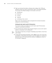
... IP address, subnet mask, and default gateway that is: Telnet 169.254.100.100 c Click OK. 2 Press Enter to enter basic setup information for the Switch. If the login prompt does not begin immediately, press Return a few times until it is connected to send line feeds with line feeds is checked within the ASCII Sending section. Using Command Line Interface via Telnet Accessing the Command Line Interface via Telnet or Windows HyperTerminal using a console cable to...
... IP address, subnet mask, and default gateway that is: Telnet 169.254.100.100 c Click OK. 2 Press Enter to enter basic setup information for the Switch. If the login prompt does not begin immediately, press Return a few times until it is connected to send line feeds with line feeds is checked within the ASCII Sending section. Using Command Line Interface via Telnet Accessing the Command Line Interface via Telnet or Windows HyperTerminal using a console cable to...
Getting Started Guide
Page 40
... the terminal emulation software for the Switch, which you have connected the cable. If the login prompt does not begin immediately, press Return a few times until it starts. 2 At the login and password prompts, enter admin as your terminal emulation software and configure the COM port settings to which are now ready to manually set to match the default settings for more information. Setting Up the Switch with IP information using the command line interface. 1 The command line interface login...
... the terminal emulation software for the Switch, which you have connected the cable. If the login prompt does not begin immediately, press Return a few times until it starts. 2 At the login and password prompts, enter admin as your terminal emulation software and configure the COM port settings to which are now ready to manually set to match the default settings for more information. Setting Up the Switch with IP information using the command line interface. 1 The command line interface login...
Getting Started Guide
Page 44
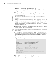
... not available, it starts. 3 At the login and password prompts, enter admin as a network connection is displayed as the Switch detects a connection to its console port. Administer physical interfaces protocol - Administer traffic management Type ? Administer sytem-level functions trafficManagement - If you have logged on correctly, the top-level menu of the command line interface is made the Switch begins the automatic IP configuration process. For help 1 Select menu option...
... not available, it starts. 3 At the login and password prompts, enter admin as a network connection is displayed as the Switch detects a connection to its console port. Administer physical interfaces protocol - Administer traffic management Type ? Administer sytem-level functions trafficManagement - If you have logged on correctly, the top-level menu of the command line interface is made the Switch begins the automatic IP configuration process. For help 1 Select menu option...

Getting Started Guide
Page 47
...the IP address of the Switch) If you have connected your workstation to browse the World Wide Web. CLI Management via To manage a Switch using the command line interface via its console port. CLI Management over To manage a Switch using the command line interface over a network the Network using a local console port connection or over the network Refer to "Setting Up SNMP Management" on page 32. 2 Check that you get an error message, check that your management workstation. Setting Up Command Line Interface Management 47 Figure 18 SNMP management over the network. If you...
...the IP address of the Switch) If you have connected your workstation to browse the World Wide Web. CLI Management via To manage a Switch using the command line interface via its console port. CLI Management over To manage a Switch using the command line interface over a network the Network using a local console port connection or over the network Refer to "Setting Up SNMP Management" on page 32. 2 Check that you get an error message, check that your management workstation. Setting Up Command Line Interface Management 47 Figure 18 SNMP management over the network. If you...
Getting Started Guide
Page 48
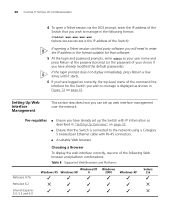
... connectors. ■ A suitable Web browser. 48 CHAPTER 3: SETTING UP FOR MANAGEMENT 4 To open a Telnet session via third party software you will need to enter the IP address in the format suitable for the Switch you wish to the network using a Category 5 twisted pair Ethernet cable with IP information as described in the following Web browser and platform combinations: Table 8 Supported Web Browsers and Platforms Netscape...
... connectors. ■ A suitable Web browser. 48 CHAPTER 3: SETTING UP FOR MANAGEMENT 4 To open a Telnet session via third party software you will need to enter the IP address in the format suitable for the Switch you wish to the network using a Category 5 twisted pair Ethernet cable with IP information as described in the following Web browser and platform combinations: Table 8 Supported Web Browsers and Platforms Netscape...

Getting Started Guide
Page 49
... is connected to the Switch using the web interface over an IP network: Over the Network 1 Check that you can browse, the IP protocol is installed. 2 Check you have changed your web browser and enter the IP address of the Switch) If you have already modified the default passwords). 5 Click on the Device View button to display the web management options. By default, all ports on the Switch are enabled on a browser by default. Web Management To manage a Switch using a port...
... is connected to the Switch using the web interface over an IP network: Over the Network 1 Check that you can browse, the IP protocol is installed. 2 Check you have changed your web browser and enter the IP address of the Switch) If you have already modified the default passwords). 5 Click on the Device View button to display the web management options. By default, all ports on the Switch are enabled on a browser by default. Web Management To manage a Switch using a port...
Getting Started Guide
Page 50
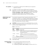
... The Switch has three default user names, and each user name has a different password and level of the "SuperStack 3 Switch Management Interface Reference Guide" for the users defined on the CLI, or CAUTION: To protect your Switch from unauthorized access, you intend to log in Table 9. To manage your Switch Table 9 Default Users User Name monitor manager admin Default Password Access Level monitor monitor - refer to login and carry out initial Switch setup. Default Users and Passwords If you must change all manageable password) parameters Use the admin default user name...
... The Switch has three default user names, and each user name has a different password and level of the "SuperStack 3 Switch Management Interface Reference Guide" for the users defined on the CLI, or CAUTION: To protect your Switch from unauthorized access, you intend to log in Table 9. To manage your Switch Table 9 Default Users User Name monitor manager admin Default Password Access Level monitor monitor - refer to login and carry out initial Switch setup. Default Users and Passwords If you must change all manageable password) parameters Use the admin default user name...

Getting Started Guide
Page 81
... number 22 3Com Knowledgebase Web Services 76 3Com URL 75 A access levels of default users 50 automatic setup 42 3Com Network Supervisor 42 console port 42 B browsers choosing 48 C cable choosing the correct 25 fiber 26 maximum length 14 pin-outs 67 CD-ROM 10 command line interface management 45 console port 17 conventions notice icons, About This Guide 8 text, About This Guide 8 cross-over configuration 25 D default settings 18 users 50 E Ethernet address of the Switch 22 INDEX 81 F factory defaults...
... number 22 3Com Knowledgebase Web Services 76 3Com URL 75 A access levels of default users 50 automatic setup 42 3Com Network Supervisor 42 console port 42 B browsers choosing 48 C cable choosing the correct 25 fiber 26 maximum length 14 pin-outs 67 CD-ROM 10 command line interface management 45 console port 17 conventions notice icons, About This Guide 8 text, About This Guide 8 cross-over configuration 25 D default settings 18 users 50 E Ethernet address of the Switch 22 INDEX 81 F factory defaults...

Getting Started Guide
Page 82
... Stacking units 23 straight-through configuration 25 Switch automatic setup 42 Switch 4200 3C number 22 console port 17 dimensions 71 Ethernet address 22 features 12 installation 19, 20 MAC address 22 power socket 17 powering-up 24 product name 22 rack mounting 21 RPS socket 17 serial number 22 size 71 stacking 23 unit information label 22 weight 71 system specifications 71 T technical support 3Com Knowledgebase Web Services 76 3Com URL 75 network suppliers 76 product repair 79 troubleshooting...
... Stacking units 23 straight-through configuration 25 Switch automatic setup 42 Switch 4200 3C number 22 console port 17 dimensions 71 Ethernet address 22 features 12 installation 19, 20 MAC address 22 power socket 17 powering-up 24 product name 22 rack mounting 21 RPS socket 17 serial number 22 size 71 stacking 23 unit information label 22 weight 71 system specifications 71 T technical support 3Com Knowledgebase Web Services 76 3Com URL 75 network suppliers 76 product repair 79 troubleshooting...


