Installation Guide
Page 1
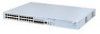
... the XFP interface module. 1 3Com Switch 4200G 10G Interface Module Installation Guide 1. Step 3: Hold the fastening screws on the rear panel of an XFP interface module Figure 2 Front panel an XFP interface module 1.2 Installation Step 1: Put on an ESD-preventive wrist strap and verify it is in along the slot guide rail until the module is properly grounded. Then remove the XFP interface module from the package. XFP Interface Module 1.1 Appearance...
... the XFP interface module. 1 3Com Switch 4200G 10G Interface Module Installation Guide 1. Step 3: Hold the fastening screws on the rear panel of an XFP interface module Figure 2 Front panel an XFP interface module 1.2 Installation Step 1: Put on an ESD-preventive wrist strap and verify it is in along the slot guide rail until the module is properly grounded. Then remove the XFP interface module from the package. XFP Interface Module 1.1 Appearance...

Installation Guide
Page 2
... verify it completely comes out of the switch chassis. Note: When installing or removing an optional interface module, pay attention to the following points: (1) Do not use . (2) When tightening the fastening screws at both sides of the optional module with your hands. (2) After removing an optional module, if no new module is to be installed, install the filler panel as soon as...
... verify it completely comes out of the switch chassis. Note: When installing or removing an optional interface module, pay attention to the following points: (1) Do not use . (2) When tightening the fastening screws at both sides of the optional module with your hands. (2) After removing an optional module, if no new module is to be installed, install the filler panel as soon as...

Installation Guide
Page 3
... the two mounting screws on the small cover plate in close contact with the switch. Note: When installing a XENPAK optical module, you do not need to fix the XENPAK optical module on the XENPAK optical module with a screwdriver and remove the small cover plate. XENPAK Optical Module 2.1 Appearance and front panel Figure 4 Appearance of a XENPAK optical module Figure 5 Front...
... the two mounting screws on the small cover plate in close contact with the switch. Note: When installing a XENPAK optical module, you do not need to fix the XENPAK optical module on the XENPAK optical module with a screwdriver and remove the small cover plate. XENPAK Optical Module 2.1 Appearance and front panel Figure 4 Appearance of a XENPAK optical module Figure 5 Front...
Installation Guide
Page 4
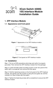
... USA www.3Com.com Part Number: 10014918 Rev. (1): Switch (2): Filler panels for optional module slots (3): Small cover plate (removed) in the middle on the filler panel (4): Push-in direction (5): XENPAK Optical Module Figure 6 Installing a XENPAK optical module Note: (1) Retain the small cover plate for future use. (2) Do not tighten the module screws more than 0.4 Nm. (3) The switch 4200G supports hot swapping of XENPAK optical modules. 2.3 Removal Step...
... USA www.3Com.com Part Number: 10014918 Rev. (1): Switch (2): Filler panels for optional module slots (3): Small cover plate (removed) in the middle on the filler panel (4): Push-in direction (5): XENPAK Optical Module Figure 6 Installing a XENPAK optical module Note: (1) Retain the small cover plate for future use. (2) Do not tighten the module screws more than 0.4 Nm. (3) The switch 4200G supports hot swapping of XENPAK optical modules. 2.3 Removal Step...


