
User Guide
Page 1
3Com Baseline Switch 2900 Family User Guide Baseline Switch 2920-SFP Plus Baseline Switch 2928-SFP Plus Baseline Switch 2952-SFP Plus Baseline Switch 2928-PWR Plus Baseline Switch 2928-HPWR Plus Manual Version: 6W102-20090810 www.3com.com 3Com Corporation 350 Campus Drive, Marlborough, MA, USA 01752 3064
3Com Baseline Switch 2900 Family User Guide Baseline Switch 2920-SFP Plus Baseline Switch 2928-SFP Plus Baseline Switch 2952-SFP Plus Baseline Switch 2928-PWR Plus Baseline Switch 2928-HPWR Plus Manual Version: 6W102-20090810 www.3com.com 3Com Corporation 350 Campus Drive, Marlborough, MA, USA 01752 3064
User Guide
Page 3
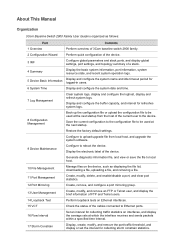
... diagnostic information file, and view or save the file to local host. 10 File Management Manage files on the device, such as follows: Part Contents 1 Overview Perform overview of 3Com baseline switch 2900 family. 2 Configuration Wizard Perform quick configuration of the device. 3 ... system logs. 8 Configuration Management Back up the configuration file or upload the configuration file to the device. About This Manual Organization 3Com Baseline Switch 2900 Family User Guide is organized as displaying the file list, downloading a file, uploading a file, and removing a file. ...
... diagnostic information file, and view or save the file to local host. 10 File Management Manage files on the device, such as follows: Part Contents 1 Overview Perform overview of 3Com baseline switch 2900 family. 2 Configuration Wizard Perform quick configuration of the device. 3 ... system logs. 8 Configuration Management Back up the configuration file or upload the configuration file to the device. About This Manual Organization 3Com Baseline Switch 2900 Family User Guide is organized as displaying the file list, downloading a file, uploading a file, and removing a file. ...

User Guide
Page 6
Related Documentation In addition to this manual, each 3com Baseline Switch 2900 documentation set includes the following: Manual Description 3Com Baseline Switch 2900 Family This guide provides all the information you need to -date 3Com product documentation on the World Wide Web at this URL: http://www.3com.com. Obtaining Documentation You can access the most up-to install Getting Started Guide and use the 3Com Baseline Switch 2900 Family.
Related Documentation In addition to this manual, each 3com Baseline Switch 2900 documentation set includes the following: Manual Description 3Com Baseline Switch 2900 Family This guide provides all the information you need to -date 3Com product documentation on the World Wide Web at this URL: http://www.3com.com. Obtaining Documentation You can access the most up-to install Getting Started Guide and use the 3Com Baseline Switch 2900 Family.

User Guide
Page 8
z The CLI provides some configuration commands to facilitate your operation. To perform other configurations not supported by the CLI, use the web interface. 1-1 These configuration methods are suitable for different application scenarios. z The web interface supports all switch 2900 series configurations. 1 Overview The 3Com baseline switch 2900 family can be configured through the command line interface (CLI), web interface, and SNMP/MIB.
z The CLI provides some configuration commands to facilitate your operation. To perform other configurations not supported by the CLI, use the web interface. 1-1 These configuration methods are suitable for different application scenarios. z The web interface supports all switch 2900 series configurations. 1 Overview The 3Com baseline switch 2900 family can be configured through the command line interface (CLI), web interface, and SNMP/MIB.
User Guide
Page 14
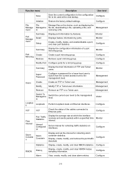
... Detail Setup Display port information by ports. Monitor Configure Configure Modify Port Configure ports for a lower-level user to switch from the current access level to Ethernet ports. Configure Summary Display the brief information of the cables connected to the ... uploading a file, and Management nt removing a file. Configure VCT VCT Check the status of FTP and Telnet users. Management Switch To Manageme nt Switch the current user level to be used at which the interface receives and sends packets within a specified time Monitor interval. Configure...
... Detail Setup Display port information by ports. Monitor Configure Configure Modify Port Configure ports for a lower-level user to switch from the current access level to Ethernet ports. Configure Summary Display the brief information of the cables connected to the ... uploading a file, and Management nt removing a file. Configure VCT VCT Check the status of FTP and Telnet users. Management Switch To Manageme nt Switch the current user level to be used at which the interface receives and sends packets within a specified time Monitor interval. Configure...
User Guide
Page 23
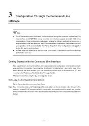
... Setting Up the Configuration Environment Set up the configuration environment as shown below.) 3-1 3 Configuration Through the Command Line Interface z The 3Com baseline switch 2900 family can connect the console port of the device to facilitate your operation, which are described in this chapter. These configuration methods... provides some configuration commands to the serial port on the console terminal, as follows: Step1 Take the console cable out of the switch, and the other configurations not supported by the CLI, use the web interface. One end of the cable is a crimped RJ...
... Setting Up the Configuration Environment Set up the configuration environment as shown below.) 3-1 3 Configuration Through the Command Line Interface z The 3Com baseline switch 2900 family can connect the console port of the device to facilitate your operation, which are described in this chapter. These configuration methods... provides some configuration commands to the serial port on the console terminal, as follows: Step1 Take the console cable out of the switch, and the other configurations not supported by the CLI, use the web interface. One end of the cable is a crimped RJ...
User Guide
Page 24
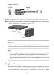
...operating system to connect to the correct port. z When connecting a PC to a powered-on switch, you are recommended to the serial port of the console terminal or PC. z When disconnecting a PC from the switch. For detailed 3-2 Figure 3-1 Console cable Step2 Plug the DB-9 female connector of the console ...cable to disconnect the DB-9 connector of the console cable from the PC after disconnecting the RJ-45 connector from a powered-on switch, you are recommended to connect the DB-9 connector of the console cable to the PC before connecting the RJ-45 connector to communicate with...
...operating system to connect to the correct port. z When connecting a PC to a powered-on switch, you are recommended to the serial port of the console terminal or PC. z When disconnecting a PC from the switch. For detailed 3-2 Figure 3-1 Console cable Step2 Plug the DB-9 female connector of the console ...cable to disconnect the DB-9 connector of the console cable from the PC after disconnecting the RJ-45 connector from a powered-on switch, you are recommended to connect the DB-9 connector of the console cable to the PC before connecting the RJ-45 connector to communicate with...
User Guide
Page 25
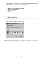
... connection in Help and Support Center on the PC running the Windows operating system. Select the serial port to be used to communicate with the switch. 1) Start the PC and run the terminal emulation program. 2) Set terminal parameters as follows: z Bits per second: 38,400 z Data bits: 8 z Parity: None z Stop bits...
... connection in Help and Support Center on the PC running the Windows operating system. Select the serial port to be used to communicate with the switch. 1) Start the PC and run the terminal emulation program. 2) Set terminal parameters as follows: z Bits per second: 38,400 z Data bits: 8 z Parity: None z Stop bits...
User Guide
Page 27
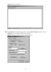
Figure 3-7 Set terminal emulation in the HyperTerminal window to VT100, and then click OK. Figure 3-6 HyperTerminal window Step5 Click Properties in Switch Properties dialog box 3-5 Click the Settings tab, set the emulation to enter the Switch Properties dialog box.
Figure 3-7 Set terminal emulation in the HyperTerminal window to VT100, and then click OK. Figure 3-6 HyperTerminal window Step5 Click Properties in Switch Properties dialog box 3-5 Click the Settings tab, set the emulation to enter the Switch Properties dialog box.
User Guide
Page 28
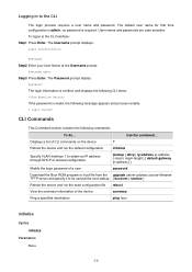
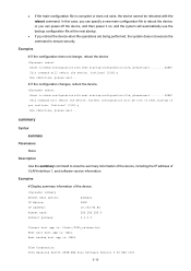
Logging In to the CLI Interface: Step1 Press Enter. The Username prompt displays: Login authentication Username: Step2 Enter your User Name at the next startup { bootrom | runtime } Reboot the device and run the default configuration initialize Specify VLAN-interface 1 to obtain an IP address through DHCP or manual configuration ipsetup { dhcp | ip address ip-address { mask | mask-length } [ default-gateway ip-address ] } Modify the login password of a user password Download the Boot ROM program or boot file from the upgrade server-address source-filename TFTP server and ...
Logging In to the CLI Interface: Step1 Press Enter. The Username prompt displays: Login authentication Username: Step2 Enter your User Name at the next startup { bootrom | runtime } Reboot the device and run the default configuration initialize Specify VLAN-interface 1 to obtain an IP address through DHCP or manual configuration ipsetup { dhcp | ip address ip-address { mask | mask-length } [ default-gateway ip-address ] } Modify the login password of a user password Download the Boot ROM program or boot file from the upgrade server-address source-filename TFTP server and ...
User Guide
Page 32
.... reboot Start to check configuration with next startup configuration file, please wait.........DONE! z If the main configuration file is : NULL 3Com Corporation 3Com Baseline Switch 2928-PWR Plus Software Version 5.20 ESS 1101 3-10 Current configuration will automatically use the backup configuration file at the next startup. summary Select menu option: Summary IP Method: IP...
.... reboot Start to check configuration with next startup configuration file, please wait.........DONE! z If the main configuration file is : NULL 3Com Corporation 3Com Baseline Switch 2928-PWR Plus Software Version 5.20 ESS 1101 3-10 Current configuration will automatically use the backup configuration file at the next startup. summary Select menu option: Summary IP Method: IP...
User Guide
Page 33
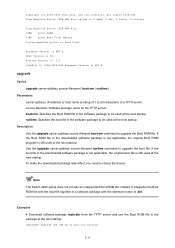
... package at the next startup. upgrade 192.168.20.41 main.bin bootrom 3-11 All rights reserved. 3Com Baseline Switch 2928-PWR Plus uptime is 0 week, 0 day, 3 hours, 11 minutes 3Com Baseline Switch 2928-PWR Plus 128M bytes DRAM 128M bytes Nand Flash Memory Config Register points to be used at the... (a string of 1 to reboot the device. Description Use the upgrade server-address source-filename bootrom command to upgrade the boot file. The Switch 2900 series does not provide an independent Boot ROM file; and its licensors. If the boot file in the software package to Nand Flash...
... package at the next startup. upgrade 192.168.20.41 main.bin bootrom 3-11 All rights reserved. 3Com Baseline Switch 2928-PWR Plus uptime is 0 week, 0 day, 3 hours, 11 minutes 3Com Baseline Switch 2928-PWR Plus 128M bytes DRAM 128M bytes Nand Flash Memory Config Register points to be used at the... (a string of 1 to reboot the device. Description Use the upgrade server-address source-filename bootrom command to upgrade the boot file. The Switch 2900 series does not provide an independent Boot ROM file; and its licensors. If the boot file in the software package to Nand Flash...
User Guide
Page 34
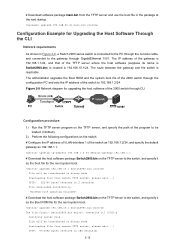
.... Overwrite it as 192.168.1.1. The administrator upgrades the Boot ROM and the system boot file of the program to the switch, and specify it ? [Y/N]:y Verifying server file... upgrade 192.168.10.1 Switch2900.bin runtime File will be loaded. (Omitted) 2) Perform the following configurations on the... 1/0/1. upgrade 192.168.20.41 main.bin runtime Configuration Example for the next system boot. The route between the gateway and the switch is 192.168.10.1/24. ipsetup ip-address 192.168.1.2 24 default-gateway 192.168.1.1 # Download the host software package Switch2900.bin on the TFTP...
.... Overwrite it as 192.168.1.1. The administrator upgrades the Boot ROM and the system boot file of the program to the switch, and specify it ? [Y/N]:y Verifying server file... upgrade 192.168.10.1 Switch2900.bin runtime File will be loaded. (Omitted) 2) Perform the following configurations on the... 1/0/1. upgrade 192.168.20.41 main.bin runtime Configuration Example for the next system boot. The route between the gateway and the switch is 192.168.10.1/24. ipsetup ip-address 192.168.1.2 24 default-gateway 192.168.1.1 # Download the host software package Switch2900.bin on the TFTP...

User Guide
Page 35
reboot After getting the new application file, reboot the switch to have the upgraded application take effect. 3-13 The specified file will be used as the boot file at the next reboot. # Reboot the switch. File downloaded successfully.
reboot After getting the new application file, reboot the switch to have the upgraded application take effect. 3-13 The specified file will be used as the boot file at the next reboot. # Reboot the switch. File downloaded successfully.
User Guide
Page 48
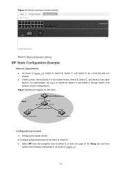
...tab, and then perform the following configurations, as shown in Figure 1-6, Switch A, Switch B, Switch C, and Switch D are slave devices. z Create a stack, where Switch A is the master device, Switch B, Switch C, and Switch D are connected with one another. Figure 1-6 Network diagram for IRF stack... 1) Configure the master device # Configure global parameters for the stack on Switch A. An administrator can log in to Switch B, Switch C and Switch D through Switch A to enter the page of Switch A to perform remote configurations. IRF Stack Configuration Example Network requirements z As...
...tab, and then perform the following configurations, as shown in Figure 1-6, Switch A, Switch B, Switch C, and Switch D are slave devices. z Create a stack, where Switch A is the master device, Switch B, Switch C, and Switch D are connected with one another. Figure 1-6 Network diagram for IRF stack... 1) Configure the master device # Configure global parameters for the stack on Switch A. An administrator can log in to Switch B, Switch C and Switch D through Switch A to enter the page of Switch A to perform remote configurations. IRF Stack Configuration Example Network requirements z As...
User Guide
Page 49
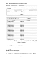
z On the page of Mask. z Select Enable from the Build Stack drop-down list. z Click Apply. Figure 1-7 Configure global parameters for the stack on Switch A. Now, switch A becomes the master device. # Configure a stack port on Switch A z Type 192.168.1.1 in Figure 1-8. 1-7 z Type 255.255.255.0 in the text box of the Setup tab, perform the following configurations, as shown in the text box of Private Net IP.
z On the page of Mask. z Select Enable from the Build Stack drop-down list. z Click Apply. Figure 1-7 Configure global parameters for the stack on Switch A. Now, switch A becomes the master device. # Configure a stack port on Switch A z Type 192.168.1.1 in Figure 1-8. 1-7 z Type 255.255.255.0 in the text box of the Setup tab, perform the following configurations, as shown in the text box of Private Net IP.
User Guide
Page 50
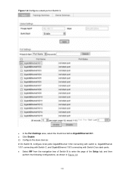
z Select IRF from the navigation tree of Switch B to enter the page of the Setup tab, and then perform the following configurations, as stack ports. Figure 1-8 Configure a stack port on Switch A z In the Port Settings area, select the check box before GigabitEthernet1/0/1. z Click Enable. 2) Configure the slave devices # On Switch B, configure local ports GigabitEthernet 1/0/2 connecting with switch A, GigabitEthernet 1/0/1 connecting with Switch C, and GigabitEthernet 1/0/3 connecting with Switch D as shown in Figure 1-9. 1-8
z Select IRF from the navigation tree of Switch B to enter the page of the Setup tab, and then perform the following configurations, as stack ports. Figure 1-8 Configure a stack port on Switch A z In the Port Settings area, select the check box before GigabitEthernet1/0/1. z Click Enable. 2) Configure the slave devices # On Switch B, configure local ports GigabitEthernet 1/0/2 connecting with switch A, GigabitEthernet 1/0/1 connecting with Switch C, and GigabitEthernet 1/0/3 connecting with Switch D as shown in Figure 1-9. 1-8
User Guide
Page 51
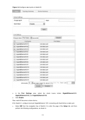
z Click Enable. Figure 1-9 Configure stack ports on Switch B z In the Port Settings area, select the check boxes before GigabitEthernet1/0/1, GigabitEthernet1/0/2, and GigabitEthernet1/0/3. z Select IRF from the navigation tree of Switch C to enter the page of the Setup tab, and then perform the following configurations, as a stack port. Now, switch B becomes a slave device. # On Switch C, configure local port GigabitEthernet 1/0/1 connecting with Switch B as shown in . 1-9
z Click Enable. Figure 1-9 Configure stack ports on Switch B z In the Port Settings area, select the check boxes before GigabitEthernet1/0/1, GigabitEthernet1/0/2, and GigabitEthernet1/0/3. z Select IRF from the navigation tree of Switch C to enter the page of the Setup tab, and then perform the following configurations, as a stack port. Now, switch B becomes a slave device. # On Switch C, configure local port GigabitEthernet 1/0/1 connecting with Switch B as shown in . 1-9
User Guide
Page 52
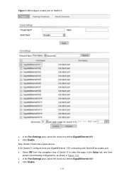
z In the Port Settings area, select the check box before GigabitEthernet1/0/1. z Click Enable. 1-10 z Select IRF from the navigation tree of Switch D to enter the page of the Setup tab, and then perform the following configurations, as a stack port. Figure 1-10 Configure a stack port on Switch C z In the Port Settings area, select the check box before GigabitEthernet1/0/1. z Click Enable. Now, Switch C becomes a slave device. # On Switch D, configure local port GigabitEthernet 1/0/1 connecting with Switch B as shown in Figure 1-10.
z In the Port Settings area, select the check box before GigabitEthernet1/0/1. z Click Enable. 1-10 z Select IRF from the navigation tree of Switch D to enter the page of the Setup tab, and then perform the following configurations, as a stack port. Figure 1-10 Configure a stack port on Switch C z In the Port Settings area, select the check box before GigabitEthernet1/0/1. z Click Enable. Now, Switch C becomes a slave device. # On Switch D, configure local port GigabitEthernet 1/0/1 connecting with Switch B as shown in Figure 1-10.
User Guide
Page 53
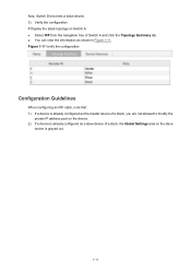
.... 1-11 Figure 1-11 Verify the configuration Configuration Guidelines When configuring an IRF stack, note that: 1) If a device is already configured as the master device of Switch A and click the Topology Summary tab. z Select IRF from the navigation tree of a stack, you are not allowed to modify the private IP address pool...
.... 1-11 Figure 1-11 Verify the configuration Configuration Guidelines When configuring an IRF stack, note that: 1) If a device is already configured as the master device of Switch A and click the Topology Summary tab. z Select IRF from the navigation tree of a stack, you are not allowed to modify the private IP address pool...


