
Getting Started Guide
Page 3
Front View Detail 15 10BASE-T/ 100BASE-TX Ports 17 Gigabit Ports 17 Console Port 17 Unit LED 18 LEDs 18 Switch 4500 - Rear View Detail 20 Power Socket 20 Open Book Warning Labels 20 Redundant Power System Socket 21 Default Settings 21 CONTENTS ABOUT THIS GUIDE Before You Start 9 Release Notes 9 About Your CD-ROM 10 Conventions 10 Related Documentation 11 Accessing Online Documentation 12 Documentation Comments 12 1 INTRODUCING THE SWITCH 4500 FAMILY About the Switch 4500 14 Summary of Hardware Features 15 Switch 4500 -
Front View Detail 15 10BASE-T/ 100BASE-TX Ports 17 Gigabit Ports 17 Console Port 17 Unit LED 18 LEDs 18 Switch 4500 - Rear View Detail 20 Power Socket 20 Open Book Warning Labels 20 Redundant Power System Socket 21 Default Settings 21 CONTENTS ABOUT THIS GUIDE Before You Start 9 Release Notes 9 About Your CD-ROM 10 Conventions 10 Related Documentation 11 Accessing Online Documentation 12 Documentation Comments 12 1 INTRODUCING THE SWITCH 4500 FAMILY About the Switch 4500 14 Summary of Hardware Features 15 Switch 4500 -
Getting Started Guide
Page 4
...SWITCH Package Contents 24 Choosing a Suitable Site 25 Rack-mounting 26 Rack Mounting the Back of your Switch 4500 (PWR only) 27 Connecting a Redundant Power Supply to your Switch 4500 PWR 28 Specifying the Redundant Power System 30 Connecting the Switch...Switch 4500 40 3 SETTING UP FOR MANAGEMENT Methods of Managing a Switch 42 Command Line Interface Management 42 Command Line Interface Management using SSH 43 Web Interface Management 43 SNMP Management 43 Setting Up Overview 44 IP Configuration 45 Preparing for Management 46 Manually Configuring IP Information 47 Connecting to the Console Port...
...SWITCH Package Contents 24 Choosing a Suitable Site 25 Rack-mounting 26 Rack Mounting the Back of your Switch 4500 (PWR only) 27 Connecting a Redundant Power Supply to your Switch 4500 PWR 28 Specifying the Redundant Power System 30 Connecting the Switch...Switch 4500 40 3 SETTING UP FOR MANAGEMENT Methods of Managing a Switch 42 Command Line Interface Management 42 Command Line Interface Management using SSH 43 Web Interface Management 43 SNMP Management 43 Setting Up Overview 44 IP Configuration 45 Preparing for Management 46 Manually Configuring IP Information 47 Connecting to the Console Port...
Getting Started Guide
Page 5
... Configured IP Information 53 Using 3Com Network Director 54 Connecting to the Console Port 54 Setting Up Command Line Interface Management 56 User Interface Overview 56 CLI Management via the Console Port 56 CLI Management over the Network 56 Setting Up Command Line Interface Management using SSH 57 Setting Up Web Interface Management 58 Pre-requisites 58 Web...
... Configured IP Information 53 Using 3Com Network Director 54 Connecting to the Console Port 54 Setting Up Command Line Interface Management 56 User Interface Overview 56 CLI Management via the Console Port 56 CLI Management over the Network 56 Setting Up Command Line Interface Management using SSH 57 Setting Up Web Interface Management 58 Pre-requisites 58 Web...

Getting Started Guide
Page 6
... o zabezpieczeniach 108 B PIN-OUTS Null Modem Cable 111 PC-AT Serial Cable 111 Modem Cable 112 Ethernet Port RJ-45 Pin Assignments 112 C TECHNICAL SPECIFICATIONS Switch 4500 (26 Port) 115 Switch 4500 (50 Port) 116 Switch 4500 PWR (26 Port) 117 Switch 4500 PWR (50 Port) 118 RPS 119 Earthing Lead 119 Upgrading from the Bootrom Interface 82 Introduction 82 TFTP 84 FTP...
... o zabezpieczeniach 108 B PIN-OUTS Null Modem Cable 111 PC-AT Serial Cable 111 Modem Cable 112 Ethernet Port RJ-45 Pin Assignments 112 C TECHNICAL SPECIFICATIONS Switch 4500 (26 Port) 115 Switch 4500 (50 Port) 116 Switch 4500 PWR (26 Port) 117 Switch 4500 PWR (50 Port) 118 RPS 119 Earthing Lead 119 Upgrading from the Bootrom Interface 82 Introduction 82 TFTP 84 FTP...

Getting Started Guide
Page 9
The guide is intended for use the following switches in their default state: ■ Switch 4500 26-Port (3CR17561-91) ■ Switch 4500 50-Port (3CR17562-91) ■ Switch 4500 PWR 26-Port (3CR17571-91) ■ Switch 4500 PWR 50-Port (3CR17572-91) All procedures described in your Switch 4500. Before You Start This section contains information about the current software release, including new features, modifications, and known problems. You should...
The guide is intended for use the following switches in their default state: ■ Switch 4500 26-Port (3CR17561-91) ■ Switch 4500 50-Port (3CR17562-91) ■ Switch 4500 PWR 26-Port (3CR17571-91) ■ Switch 4500 PWR 50-Port (3CR17572-91) All procedures described in your Switch 4500. Before You Start This section contains information about the current software release, including new features, modifications, and known problems. You should...

Getting Started Guide
Page 14
...; 1 24 2* 2* 2† 1 1 48 2* 2* 2† 1 1 * Combo SFP and 10/100/1000 Ports † 1000BASE-T SFP transceiver installed in last two 1000BASE-X SFP ports The Switch 4500 Family provides workgroup connectivity at 10- and 100-Mbps, and high-speed Gigabit ports for stacking, uplinks to the "Command Reference Guide" on the CD-ROM that accompanies the Switch. Table 3 summarizes what each Switch consists of management...
...; 1 24 2* 2* 2† 1 1 48 2* 2* 2† 1 1 * Combo SFP and 10/100/1000 Ports † 1000BASE-T SFP transceiver installed in last two 1000BASE-X SFP ports The Switch 4500 Family provides workgroup connectivity at 10- and 100-Mbps, and high-speed Gigabit ports for stacking, uplinks to the "Command Reference Guide" on the CD-ROM that accompanies the Switch. Table 3 summarizes what each Switch consists of management...

Getting Started Guide
Page 15
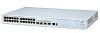
...: (100Base-TX) Green = 100Mbps Yellow = 10Mbps (1000Base-X) Green = 1000Mbps Yellow = 10/100Mbps Duplex: Green = Full Duplex, Yellow = Half Duplex Console Port Unit LED 3CR17561-91 SuperStack 3 Switch 4500 26-Port 25 26 27/25 28/26 10/100BASE-TX 10/100BASE-TX Ports 1000BASE-X 10/100/1000BASE-T 1000BASE-X Combo Port Pair 10/100/1000BASE-T Combo Port Pair Power LED Flow Control In full duplex operation all...
...: (100Base-TX) Green = 100Mbps Yellow = 10Mbps (1000Base-X) Green = 1000Mbps Yellow = 10/100Mbps Duplex: Green = Full Duplex, Yellow = Half Duplex Console Port Unit LED 3CR17561-91 SuperStack 3 Switch 4500 26-Port 25 26 27/25 28/26 10/100BASE-TX 10/100BASE-TX Ports 1000BASE-X 10/100/1000BASE-T 1000BASE-X Combo Port Pair 10/100/1000BASE-T Combo Port Pair Power LED Flow Control In full duplex operation all...

Getting Started Guide
Page 16
... transceivers in last two ports) Figure 3 Switch 4500 26-Port PWR - 16 CHAPTER 1: INTRODUCING THE SWITCH 4500 FAMILY Figure 2 Switch 4500 50-Port - Only connect RJ-45 data connectors, network telephony systems, or network telephones to a traditional PBX or public telephone network. Yellow=Fault, Flashing Green=Over Budget 10/100BASE-TX Ports Console Port 3CR17572-91 SuperStack 3 Switch 4500 PWR 50-Port Unit LED PWR LED...
... transceivers in last two ports) Figure 3 Switch 4500 26-Port PWR - 16 CHAPTER 1: INTRODUCING THE SWITCH 4500 FAMILY Figure 2 Switch 4500 50-Port - Only connect RJ-45 data connectors, network telephony systems, or network telephones to a traditional PBX or public telephone network. Yellow=Fault, Flashing Green=Over Budget 10/100BASE-TX Ports Console Port 3CR17572-91 SuperStack 3 Switch 4500 PWR 50-Port Unit LED PWR LED...

Getting Started Guide
Page 17
...using copper Ethernet cabling. Gigabit Ports The Switch 4500 26 Port has two 1000BASE-X SFP ports and two 10/100/1000BASE-T ports, which auto-negotiation is negotiated with these switches and can manually set these ports is 100 m (328 ft) over ). Port 26 with Port 52. This offers you ...right-most ports of -band management. Front View Detail 17 10BASE-T/ 100BASE-TX Ports The Switch 4500 has 24 or 48 auto-negotiating 10BASE-T/100BASE-TX ports configured as dual personality combination ports pairing one 1000BASE-X and one time. The port pairings of the 50-Port models are...
...using copper Ethernet cabling. Gigabit Ports The Switch 4500 26 Port has two 1000BASE-X SFP ports and two 10/100/1000BASE-T ports, which auto-negotiation is negotiated with these switches and can manually set these ports is 100 m (328 ft) over ). Port 26 with Port 52. This offers you ...right-most ports of -band management. Front View Detail 17 10BASE-T/ 100BASE-TX Ports The Switch 4500 has 24 or 48 auto-negotiating 10BASE-T/100BASE-TX ports configured as dual personality combination ports pairing one 1000BASE-X and one time. The port pairings of the 50-Port models are...

Getting Started Guide
Page 18
... not receiving power or there is a seven segment display visible on the front of the Switch, and how to indicate the unit number in progress. 18 CHAPTER 1: INTRODUCING THE SWITCH 4500 FAMILY Unit LED The Unit LED is a fault with the Power Supply Unit. For information on ...page 68. Green flashing 'f' There has been a fan failure. PWR LED Green The Switch is in a fabric, POST test ID and software upgrade information. Mode LED (3CR17571-91 and 3CR17572-91 only) Speed Green 10/100 Port Speed and Activity, 1000 SFP Status and Activity, or Stack Status and Activity. Duplex Yellow...
... not receiving power or there is a seven segment display visible on the front of the Switch, and how to indicate the unit number in progress. 18 CHAPTER 1: INTRODUCING THE SWITCH 4500 FAMILY Unit LED The Unit LED is a fault with the Power Supply Unit. For information on ...page 68. Green flashing 'f' There has been a fan failure. PWR LED Green The Switch is in a fabric, POST test ID and software upgrade information. Mode LED (3CR17571-91 and 3CR17572-91 only) Speed Green 10/100 Port Speed and Activity, 1000 SFP Status and Activity, or Stack Status and Activity. Duplex Yellow...

Getting Started Guide
Page 19
...-91 and 3CR17572-91 only) Green Full duplex packets are being over budget. Off No link is present. Yellow PoE error, no RPS supply connected. 10BASE-T/100-TX Port LEDs Speed Green A high speed (100 Mbps) link is unable to supply power due to the port. Yellow Flashing The port has failed POST. Switch 4500 - Yellow A low speed (10 Mbps...
...-91 and 3CR17572-91 only) Green Full duplex packets are being over budget. Off No link is present. Yellow PoE error, no RPS supply connected. 10BASE-T/100-TX Port LEDs Speed Green A high speed (100 Mbps) link is unable to supply power due to the port. Yellow Flashing The port has failed POST. Switch 4500 - Yellow A low speed (10 Mbps...
Getting Started Guide
Page 21
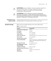
... IEEE Std 802.1Q-1998 learning operational Management VLAN Any VLAN for all ports) and System Socket redundant power for the Switch 4500 Family: Table 6 Default Settings Feature Switch 4500 Automatic IP Configuration Enabled Port Status Enabled Port Speed Auto-negotiated Duplex Mode Auto-negotiated Power over Ethernet Enabled (3CR17571-91 and 3CR17572-91 only) Flow Control Auto-negotiated Broadcast...
... IEEE Std 802.1Q-1998 learning operational Management VLAN Any VLAN for all ports) and System Socket redundant power for the Switch 4500 Family: Table 6 Default Settings Feature Switch 4500 Automatic IP Configuration Enabled Port Status Enabled Port Speed Auto-negotiated Duplex Mode Auto-negotiated Power over Ethernet Enabled (3CR17571-91 and 3CR17572-91 only) Flow Control Auto-negotiated Broadcast...

Getting Started Guide
Page 22
22 CHAPTER 1: INTRODUCING THE SWITCH 4500 FAMILY Feature Traffic Prioritization Port Security Configuration Save and Restore Switch 4500 All ports prioritize NBX VoIP traffic (LAN and IP). All ports set to "best effort" for all other traffic. Disabled per port Disabled
22 CHAPTER 1: INTRODUCING THE SWITCH 4500 FAMILY Feature Traffic Prioritization Port Security Configuration Save and Restore Switch 4500 All ports prioritize NBX VoIP traffic (LAN and IP). All ports set to "best effort" for all other traffic. Disabled per port Disabled

Getting Started Guide
Page 28
....3af (PoE) specification, the -48V output must be isolated from an RPS, the unit must be used with your Switch 4500 PWR The Switch 4500 PWR 26 and 50 port have this information if you contact 3Com Technical Support. WARNING: A standard 'positive-earthed' -48V redundant power system suitable for use with telecommunications equipment should only be...
....3af (PoE) specification, the -48V output must be isolated from an RPS, the unit must be used with your Switch 4500 PWR The Switch 4500 PWR 26 and 50 port have this information if you contact 3Com Technical Support. WARNING: A standard 'positive-earthed' -48V redundant power system suitable for use with telecommunications equipment should only be...

Getting Started Guide
Page 29
... is useful in three different ways: ■ AC Mains only - if a Switch is available. the Switch does not need an AC supply and the resiliency is attached. The RPS provides three main benefits to PoE Ports - The Switch 4500 PWR units can also be approved as a SELV output in the event of a... DC power failure. ■ DC only - the internal AC Power Supply of a PoE Switch can be used to supplement additional power (up to a ...
... is useful in three different ways: ■ AC Mains only - if a Switch is available. the Switch does not need an AC supply and the resiliency is attached. The RPS provides three main benefits to PoE Ports - The Switch 4500 PWR units can also be approved as a SELV output in the event of a... DC power failure. ■ DC only - the internal AC Power Supply of a PoE Switch can be used to supplement additional power (up to a ...

Getting Started Guide
Page 30
...together so that meets the requirements defined in Appendix C on System page 115. The unit is powered by the AC mains. PoE ports can provide up to provide N+1 rectifier redundancy. The outputs of two rectifiers are unable to obtain the power they are required for ...be dropped as they require. The total power available to : http://www.3Com.com/RPS The 3Com recommended RPS generates -48V DC power using power supply units (or rectifiers). 30 CHAPTER 2: INSTALLING THE SWITCH Table 8 Switch Power Inputs Power Input before Power Input after User Intervention User Intervention AC ...
...together so that meets the requirements defined in Appendix C on System page 115. The unit is powered by the AC mains. PoE ports can provide up to provide N+1 rectifier redundancy. The outputs of two rectifiers are unable to obtain the power they are required for ...be dropped as they require. The total power available to : http://www.3Com.com/RPS The 3Com recommended RPS generates -48V DC power using power supply units (or rectifiers). 30 CHAPTER 2: INSTALLING THE SWITCH Table 8 Switch Power Inputs Power Input before Power Input after User Intervention User Intervention AC ...

Getting Started Guide
Page 33
... the total power budget for example, the Switch is used to connect a 3Com 11 Mbps Wireless LAN Access Point 8500 to the network. RPS LED The RPS status LED on the front of the Switch 4500 PWR indicates the status of the ports on page 115. RPS supply is no... power supply that can supply power to the device, providing that accompanies your Switch 4500 PWR 33 The -48V DC power will take priority over Ethernet is a self-configuring protocol. A PoE Switch combines the functionality of its 10/100 ports over Ethernet (PoE) units can power multiple devices. Alternatively use the earthing ...
... the total power budget for example, the Switch is used to connect a 3Com 11 Mbps Wireless LAN Access Point 8500 to the network. RPS LED The RPS status LED on the front of the Switch 4500 PWR indicates the status of the ports on page 115. RPS supply is no... power supply that can supply power to the device, providing that accompanies your Switch 4500 PWR 33 The -48V DC power will take priority over Ethernet is a self-configuring protocol. A PoE Switch combines the functionality of its 10/100 ports over Ethernet (PoE) units can power multiple devices. Alternatively use the earthing ...

Getting Started Guide
Page 35
...a problem, see "Solving Problems Indicated by connecting or disconnecting the power cord. Therefore you can automatically detect whether to get your Switch 4500 powered-up and operating normally. The Power-up Sequence 35 The Power-up Sequence The following sequence of LEDs the LEDs light. Powering...over capability. Choosing the Correct Cables All of the power cord into the power socket at the rear of the Switch. 2 Plug the other end of the ports on page 68 for the LED. Switch 4500 1 Plug the power cord into your Switch is they have a cross-over cable (MDIX). The...
...a problem, see "Solving Problems Indicated by connecting or disconnecting the power cord. Therefore you can automatically detect whether to get your Switch 4500 powered-up and operating normally. The Power-up Sequence 35 The Power-up Sequence The following sequence of LEDs the LEDs light. Powering...over capability. Choosing the Correct Cables All of the power cord into the power socket at the rear of the Switch. 2 Plug the other end of the ports on page 68 for the LED. Switch 4500 1 Plug the power cord into your Switch is they have a cross-over cable (MDIX). The...

Getting Started Guide
Page 36
...is disabled, all wires at least Category 5 twisted pair cable - WARNING: The Switch 4500 PWR supports Power over cable. See Table 13. 3Com recommends that you briefly connect the cable to a grounded port before connecting network equipment. If you do not, the cable's Electrostatic Discharge (..., and the other devices if auto-negotiation is enabled. These ports should only be used for Ethernet wiring within the same building. Many ports on 10/100 ports only. 36 CHAPTER 2: INSTALLING THE SWITCH The Auto-MDIX feature only operates when auto-negotiation is disabled ...
...is disabled, all wires at least Category 5 twisted pair cable - WARNING: The Switch 4500 PWR supports Power over cable. See Table 13. 3Com recommends that you briefly connect the cable to a grounded port before connecting network equipment. If you do not, the cable's Electrostatic Discharge (..., and the other devices if auto-negotiation is enabled. These ports should only be used for Ethernet wiring within the same building. Many ports on 10/100 ports only. 36 CHAPTER 2: INSTALLING THE SWITCH The Auto-MDIX feature only operates when auto-negotiation is disabled ...

Getting Started Guide
Page 37
...to single-mode and multi-mode fiber-optic cables. Table 14 shows the range for the 1000BASE-X SFP Ports The 1000BASE-SX SFP transceiver supports a direct connection to a multi-mode fiber-optic cable. The 1000BASE-...lengths of up Sequence 37 Choosing the Correct Cables for each connection: Table 14 1000BASE-X SFP Port Cable Range Fiber Type 1000BASE-SX Multi-mode Multi-mode Multi-mode Multi-mode 1000BASE-LX ...400 2m - 550m (6.6 ft - 1804.6 ft) 50 500 2m - 550m (6.6 ft - 1804.6 ft) 9 - 2m - 10,000m (6.6 ft - 32, 810 ft) 9 core - 2m - 70 km (6.6 ft - 43 miles) The Power-up to...
...to single-mode and multi-mode fiber-optic cables. Table 14 shows the range for the 1000BASE-X SFP Ports The 1000BASE-SX SFP transceiver supports a direct connection to a multi-mode fiber-optic cable. The 1000BASE-...lengths of up Sequence 37 Choosing the Correct Cables for each connection: Table 14 1000BASE-X SFP Port Cable Range Fiber Type 1000BASE-SX Multi-mode Multi-mode Multi-mode Multi-mode 1000BASE-LX ...400 2m - 550m (6.6 ft - 1804.6 ft) 50 500 2m - 550m (6.6 ft - 1804.6 ft) 9 - 2m - 10,000m (6.6 ft - 32, 810 ft) 9 core - 2m - 70 km (6.6 ft - 43 miles) The Power-up to...


