
User Manual
Page 1
SuperStack® 3 Switch 4400 Series Getting Started Guide Switch 4400 (3C17203) Switch 4400 (3C17204) Switch 4400 PWR (3C17205) Switch 4400 SE (3C17206) Switch 4400 FX (3C17210) http://www.3com.com/ Part No. DUA1720-3AAA07 Published March 2004
SuperStack® 3 Switch 4400 Series Getting Started Guide Switch 4400 (3C17203) Switch 4400 (3C17204) Switch 4400 PWR (3C17205) Switch 4400 SE (3C17206) Switch 4400 FX (3C17210) http://www.3com.com/ Part No. DUA1720-3AAA07 Published March 2004
User Manual
Page 3
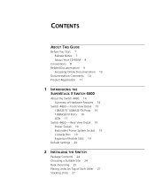
...Release Notes 7 About Your CD-ROM 8 Conventions 8 Related Documentation 9 Accessing Online Documentation 10 Documentation Comments 10 Product Registration 11 1 INTRODUCING THE SUPERSTACK 3 SWITCH 4400 About the Switch 4400 14 Summary of Each Other 27 Stacking Units 27 Rear View Detail 19 Power Socket 19 Redundant Power System Socket 19 Console Port 19... 20 2 INSTALLING THE SWITCH Package Contents 24 Choosing a Suitable Site 24 Rack-mounting 25 Placing Units On Top of Hardware Features 14 Switch 4400 - Front View Detail 15 10BASE-T/ 100BASE-TX Ports 16 100BASE-FX Ports 16 LEDs 17 Switch...
...Release Notes 7 About Your CD-ROM 8 Conventions 8 Related Documentation 9 Accessing Online Documentation 10 Documentation Comments 10 Product Registration 11 1 INTRODUCING THE SUPERSTACK 3 SWITCH 4400 About the Switch 4400 14 Summary of Each Other 27 Stacking Units 27 Rear View Detail 19 Power Socket 19 Redundant Power System Socket 19 Console Port 19... 20 2 INSTALLING THE SWITCH Package Contents 24 Choosing a Suitable Site 24 Rack-mounting 25 Placing Units On Top of Hardware Features 14 Switch 4400 - Front View Detail 15 10BASE-T/ 100BASE-TX Ports 16 100BASE-FX Ports 16 LEDs 17 Switch...
User Manual
Page 4
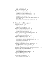
... LEDs 30 Connecting a Redundant Power System 30 Using Power over Ethernet 31 Choosing the Correct Cables (Switch 4400, 4400 SE and 4400 PWR) 32 Choosing the Correct Cables (Switch 4400 FX) 33 3 SETTING UP FOR MANAGEMENT Setting Up Overview 36 IP Configuration 37 Preparing for Management 38 ...Manually Configuring IP Information 39 Connecting to a Front Panel Port 39 Connecting to the Console Port 42 Viewing Automatically Configured IP Information 46 Using 3Com Network Supervisor...
... LEDs 30 Connecting a Redundant Power System 30 Using Power over Ethernet 31 Choosing the Correct Cables (Switch 4400, 4400 SE and 4400 PWR) 32 Choosing the Correct Cables (Switch 4400 FX) 33 3 SETTING UP FOR MANAGEMENT Setting Up Overview 36 IP Configuration 37 Preparing for Management 38 ...Manually Configuring IP Information 39 Connecting to a Front Panel Port 39 Connecting to the Console Port 42 Viewing Automatically Configured IP Information 46 Using 3Com Network Supervisor...

User Manual
Page 5
... 73 PC-AT Serial Cable 73 Modem Cable 74 RJ-45 Pin Assignments 74 C TECHNICAL SPECIFICATIONS Switch 4400 (24-port) and Switch 4400 SE 77 Switch 4400 PWR (24-port) 79 Switch 4400 (48-port) 80 Switch 4400 FX 81 D OBTAINING SUPPORT FOR YOUR PRODUCT Register Your Product to Gain Service Benefits 83 Purchase Value...
... 73 PC-AT Serial Cable 73 Modem Cable 74 RJ-45 Pin Assignments 74 C TECHNICAL SPECIFICATIONS Switch 4400 (24-port) and Switch 4400 SE 77 Switch 4400 PWR (24-port) 79 Switch 4400 (48-port) 80 Switch 4400 FX 81 D OBTAINING SUPPORT FOR YOUR PRODUCT Register Your Product to Gain Service Benefits 83 Purchase Value...
User Manual
Page 7
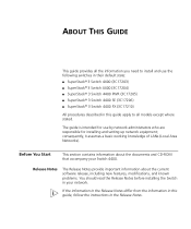
... are responsible for use the following switches in their default state: ■ SuperStack® 3 Switch 4400 (3C17203) ■ SuperStack® 3 Switch 4400 (3C17204) ■ SuperStack® 3 Switch 4400 PWR (3C17205) ■ SuperStack® 3 Switch 4400 SE (3C17206) ■ SuperStack® 3 Switch 4400 FX (3C17210) All procedures described in this guide, follow the instructions in your Switch...
... are responsible for use the following switches in their default state: ■ SuperStack® 3 Switch 4400 (3C17203) ■ SuperStack® 3 Switch 4400 (3C17204) ■ SuperStack® 3 Switch 4400 PWR (3C17205) ■ SuperStack® 3 Switch 4400 SE (3C17206) ■ SuperStack® 3 Switch 4400 FX (3C17210) All procedures described in this guide, follow the instructions in your Switch...

User Manual
Page 8
... Wide Web site: http://www.3com.com/ Conventions Table 1 and Table 2 list conventions that you must enter the command exactly as it appears on page 9 for the Switch 4400 - Syntax The word "syntax" means that appear in angle brackets. Example: To display port information, enter ...the following : ■ Online documentation for details. ■ 3Com Network Supervisor - refer to -use the following syntax: ...
... Wide Web site: http://www.3com.com/ Conventions Table 1 and Table 2 list conventions that you must enter the command exactly as it appears on page 9 for the Switch 4400 - Syntax The word "syntax" means that appear in angle brackets. Example: To display port information, enter ...the following : ■ Online documentation for details. ■ 3Com Network Supervisor - refer to -use the following syntax: ...

User Manual
Page 11
...documentation at this e-mail address. Questions related to technical support or sales should be directed in the first instance to your product: http://www.3com.com/register Product Registration Product Registration 11 Please include the following information when commenting: ■ Document title ■ Document part number (on... the title page) ■ Page number (if appropriate) Example: Part Number DUA1720-3AAA07 SuperStack 3 Switch 4400 Series Getting Started Guide Page 21 Please note that we can now register your SuperStack 3 Switch on the...
...documentation at this e-mail address. Questions related to technical support or sales should be directed in the first instance to your product: http://www.3com.com/register Product Registration Product Registration 11 Please include the following information when commenting: ■ Document title ■ Document part number (on... the title page) ■ Page number (if appropriate) Example: Part Number DUA1720-3AAA07 SuperStack 3 Switch 4400 Series Getting Started Guide Page 21 Please note that we can now register your SuperStack 3 Switch on the...

User Manual
Page 13
Rear View Detail ■ Default Settings 1 INTRODUCING THE SUPERSTACK 3 SWITCH 4400 This chapter contains introductory information about the Switch 4400 and how it can be used in your network. It covers summaries of hardware and software features and also the following topics: ■ About the Switch 4400 ■ Switch 4400 - Front View Detail ■ Switch 4400 -
Rear View Detail ■ Default Settings 1 INTRODUCING THE SUPERSTACK 3 SWITCH 4400 This chapter contains introductory information about the Switch 4400 and how it can be used in your network. It covers summaries of hardware and software features and also the following topics: ■ About the Switch 4400 ■ Switch 4400 - Front View Detail ■ Switch 4400 -

User Manual
Page 14
... device, it . Summary of Hardware Features Table 3 summarizes the hardware features that are installed in the stack can also add the Switch 4400 to 64 permanent entries Auto-negotiation ■ Supported on all ports ■ Auto MDI/MDI-X (not 3C17210) Forwarding Modes Store and ... Ethernet on all front panel ports (3C17205 only). 14 CHAPTER 1: INTRODUCING THE SUPERSTACK 3 SWITCH 4400 About the Switch 4400 The Switch 4400 is enabled on each port by the Switch 4400. You can be automatically detected and power supplied to server connection. These allow easy connection of ...
... device, it . Summary of Hardware Features Table 3 summarizes the hardware features that are installed in the stack can also add the Switch 4400 to 64 permanent entries Auto-negotiation ■ Supported on all ports ■ Auto MDI/MDI-X (not 3C17210) Forwarding Modes Store and ... Ethernet on all front panel ports (3C17205 only). 14 CHAPTER 1: INTRODUCING THE SUPERSTACK 3 SWITCH 4400 About the Switch 4400 The Switch 4400 is enabled on each port by the Switch 4400. You can be automatically detected and power supplied to server connection. These allow easy connection of ...

User Manual
Page 15
... P 19 S P 20 S P 21 S P 22 S P 23 S P 24 S Status - Green = Full Duplex Yellow = 10Mbps Yellow = Half Duplex on = enabled, link OK flashing = disabled Switch 4400 12 34 5 67 8 Unit Module 1 PS PS Power/Self test Module 2 34 56 78 3C17203 SuperStack© 3 Unit LEDs Module LEDs (Packet and Status) Figure... 3 Switch 4400 PWR - front view Front View Detail 15 Switch 4400 - front view Port LEDs (Packet and Status) Figure 2 Switch 4400 (24-port) / Switch 4400 SE - Switch 4400 - Front View Detail Figure 1 Switch 4400 FX - Green = 100Mbps Packet ...
... P 19 S P 20 S P 21 S P 22 S P 23 S P 24 S Status - Green = Full Duplex Yellow = 10Mbps Yellow = Half Duplex on = enabled, link OK flashing = disabled Switch 4400 12 34 5 67 8 Unit Module 1 PS PS Power/Self test Module 2 34 56 78 3C17203 SuperStack© 3 Unit LEDs Module LEDs (Packet and Status) Figure... 3 Switch 4400 PWR - front view Front View Detail 15 Switch 4400 - front view Port LEDs (Packet and Status) Figure 2 Switch 4400 (24-port) / Switch 4400 SE - Switch 4400 - Front View Detail Figure 1 Switch 4400 FX - Green = 100Mbps Packet ...

User Manual
Page 16
... data cables with shielded or unshielded jacks can manually set these ports to these data sockets. 10BASE-T/ 100BASE-TX Ports The Switch 4400, 4400 SE and 4400 PWR have 24 or 48 auto-negotiating 10BASE-T/100BASE-TX ports configured as standard traditional telephone sockets, or to connect the unit to... half duplex or 100BASE-TX full duplex. Alternatively, you can be used as Auto MDIX (cross-over Category 5 twisted pair cable. The Switch 4400 PWR incorporates a LED Mode Button on the front panel, which when pressed changes the mode of the 24 front panel ports in conformance to ...
... data cables with shielded or unshielded jacks can manually set these ports to these data sockets. 10BASE-T/ 100BASE-TX Ports The Switch 4400, 4400 SE and 4400 PWR have 24 or 48 auto-negotiating 10BASE-T/100BASE-TX ports configured as standard traditional telephone sockets, or to connect the unit to... half duplex or 100BASE-TX full duplex. Alternatively, you can be used as Auto MDIX (cross-over Category 5 twisted pair cable. The Switch 4400 PWR incorporates a LED Mode Button on the front panel, which when pressed changes the mode of the 24 front panel ports in conformance to ...

User Manual
Page 17
... 4 LED behavior LED Color Indicates Power/Self Test LED Green The Switch is enabled (not 4400 FX). If a port fails the Switch passes its Power On Self Test and continues to color. Yellow Half duplex packets are being transmitted/received on ... On Self Test or A port has failed and has been automatically disabled. Front View Detail 17 connector that the Port Status LED is disabled (not 4400 FX). Port LEDs Packet Green Full duplex packets are disabled. Green flashing A high speed (100 Mbps) link is present, but the port is quickly flashing...
... 4 LED behavior LED Color Indicates Power/Self Test LED Green The Switch is enabled (not 4400 FX). If a port fails the Switch passes its Power On Self Test and continues to color. Yellow Half duplex packets are being transmitted/received on ... On Self Test or A port has failed and has been automatically disabled. Front View Detail 17 connector that the Port Status LED is disabled (not 4400 FX). Port LEDs Packet Green Full duplex packets are disabled. Green flashing A high speed (100 Mbps) link is present, but the port is quickly flashing...

User Manual
Page 18
... the Switch is stand-alone and not part of that is no power supplied on port. The Switch physically forms a stack with other Switch 4400 units, but cannot be managed as a percentage of the unit that stack until all units have been upgraded to unit over Ethernet POST error ... Port LEDs are disabled. Status Refer to the port. 18 CHAPTER 1: INTRODUCING THE SUPERSTACK 3 SWITCH 4400 LED Color Indicates Port LEDs - Unit LEDs 1-8 Green When the Switch forms a stack with other Switch 4400 units, the LED indicates the position of the unit in the stack and that a link is in...
... the Switch is stand-alone and not part of that is no power supplied on port. The Switch physically forms a stack with other Switch 4400 units, but cannot be managed as a percentage of the unit that stack until all units have been upgraded to unit over Ethernet POST error ... Port LEDs are disabled. Status Refer to the port. 18 CHAPTER 1: INTRODUCING THE SUPERSTACK 3 SWITCH 4400 LED Color Indicates Port LEDs - Unit LEDs 1-8 Green When the Switch forms a stack with other Switch 4400 units, the LED indicates the position of the unit in the stack and that a link is in...

User Manual
Page 19
...to your supplier for more information. These allow the Switch to install Expansion Modules. Contact your Switch. Rear View Detail 19 Switch 4400 - Redundant Power To protect against internal power supply failure, you can use these slots to support various forms of -band management.... WARNING: When an Expansion Module is not installed, ensure the blanking plate is set to be stacked with a suitable tool. Switch 4400 - rear view View Detail Power Socket The Switch automatically adjusts its power setting to a SuperStack 3 Advanced Redundant Power System (RPS). ...
...to your supplier for more information. These allow the Switch to install Expansion Modules. Contact your Switch. Rear View Detail 19 Switch 4400 - Redundant Power To protect against internal power supply failure, you can use these slots to support various forms of -band management.... WARNING: When an Expansion Module is not installed, ensure the blanking plate is set to be stacked with a suitable tool. Switch 4400 - rear view View Detail Power Socket The Switch automatically adjusts its power setting to a SuperStack 3 Advanced Redundant Power System (RPS). ...

User Manual
Page 20
... Traffic Prioritization All ports prioritize NBX VoIP traffic (LAN and IP). 20 CHAPTER 1: INTRODUCING THE SUPERSTACK 3 SWITCH 4400 Default Settings Table 5 shows the default settings for the Switch 4400: Table 5 Default Settings Feature Switch 4400 Automatic IP Configuration Enabled Port Status Enabled Port Speed 10/100 Mbps ports are auto-negotiated MT-RJ...
... Traffic Prioritization All ports prioritize NBX VoIP traffic (LAN and IP). 20 CHAPTER 1: INTRODUCING THE SUPERSTACK 3 SWITCH 4400 Default Settings Table 5 shows the default settings for the Switch 4400: Table 5 Default Settings Feature Switch 4400 Automatic IP Configuration Enabled Port Status Enabled Port Speed 10/100 Mbps ports are auto-negotiated MT-RJ...
User Manual
Page 21
If you initialize a Switch unit by selecting System > Control > Initialize in the Web interface or by entering system control initialize in the Command Line Interface, the following settings are retained to allow you to connect to the Switch 4400 SE Enhanced Software Upgrade (3C17207). Default Settings 21 To make SSH, Webcache redirection, RADIUS (including 802.1x Network Login), Auto VLAN assignment, and Traffic Prioritization available on the SuperStack 3 Switch 4400 SE, upgrade the product to and manage the Switch: ■ IP Address ■ Subnet Mask ■ Default Router
If you initialize a Switch unit by selecting System > Control > Initialize in the Web interface or by entering system control initialize in the Command Line Interface, the following settings are retained to allow you to connect to the Switch 4400 SE Enhanced Software Upgrade (3C17207). Default Settings 21 To make SSH, Webcache redirection, RADIUS (including 802.1x Network Login), Auto VLAN assignment, and Traffic Prioritization available on the SuperStack 3 Switch 4400 SE, upgrade the product to and manage the Switch: ■ IP Address ■ Subnet Mask ■ Default Router

User Manual
Page 22
22 CHAPTER 1: INTRODUCING THE SUPERSTACK 3 SWITCH 4400
22 CHAPTER 1: INTRODUCING THE SUPERSTACK 3 SWITCH 4400

User Manual
Page 23
...must read the safety information provided in diesem Handbuch aufgefuehrt sind. Before installing or removing any components from the Switch 4400 or carrying out any maintenance procedures, you need to install and set up Sequence WARNING: Safety Information. Avant d'installer... a Suitable Site ■ Rack-mounting ■ Placing Units On Top of this guide. Bevor Sie Komponenten aus dem Switch 4400 entfernen oder dem Switch 4400 hinzufuegen oder Instandhaltungsarbeiten verrichten, lesen Sie die Sicherheitsanweisungen, die in Appendix A (Anhang A) in Appendix A of Each Other ■...
...must read the safety information provided in diesem Handbuch aufgefuehrt sind. Before installing or removing any components from the Switch 4400 or carrying out any maintenance procedures, you need to install and set up Sequence WARNING: Safety Information. Avant d'installer... a Suitable Site ■ Rack-mounting ■ Placing Units On Top of this guide. Bevor Sie Komponenten aus dem Switch 4400 entfernen oder dem Switch 4400 hinzufuegen oder Instandhaltungsarbeiten verrichten, lesen Sie die Sicherheitsanweisungen, die in Appendix A (Anhang A) in Appendix A of Each Other ■...

User Manual
Page 25
Remove all cables from the Switch before continuing. Rack-mounting The Switch 4400 is 1U high and will fit in a clean, air conditioned environment. ■ No more than eight Switch units are placed on one another, if the ...
Remove all cables from the Switch before continuing. Rack-mounting The Switch 4400 is 1U high and will fit in a clean, air conditioned environment. ■ No more than eight Switch units are placed on one another, if the ...

User Manual
Page 27
...the smaller units must have an unused expansion slot to allow a Cascade Module to the underside of the lower unit. Figure 7 Stacking two Switch 4400 units 3C17224 Module 2 UP SuperStack 3 Cascade Module 3C17224 Module 2 DOWN SuperStack 3 Cascade Module Switch 2 Switch 1 To stack more than two...will need to order the SuperStack 3 Switch Cascade Stacking Kit (3C17227). Both Switches must be stacked with a normal Switch 4400 SE. The SuperStack 3 Switch 4400 SE can be stacked together and then treated as a single manageable unit with the recesses of each corner. The kit consists...
...the smaller units must have an unused expansion slot to allow a Cascade Module to the underside of the lower unit. Figure 7 Stacking two Switch 4400 units 3C17224 Module 2 UP SuperStack 3 Cascade Module 3C17224 Module 2 DOWN SuperStack 3 Cascade Module Switch 2 Switch 1 To stack more than two...will need to order the SuperStack 3 Switch Cascade Stacking Kit (3C17227). Both Switches must be stacked with a normal Switch 4400 SE. The SuperStack 3 Switch 4400 SE can be stacked together and then treated as a single manageable unit with the recesses of each corner. The kit consists...