User Manual
Page 1
DUA1720-3AAA07 Published March 2004 SuperStack® 3 Switch 4400 Series Getting Started Guide Switch 4400 (3C17203) Switch 4400 (3C17204) Switch 4400 PWR (3C17205) Switch 4400 SE (3C17206) Switch 4400 FX (3C17210) http://www.3com.com/ Part No.
DUA1720-3AAA07 Published March 2004 SuperStack® 3 Switch 4400 Series Getting Started Guide Switch 4400 (3C17203) Switch 4400 (3C17204) Switch 4400 PWR (3C17205) Switch 4400 SE (3C17206) Switch 4400 FX (3C17210) http://www.3com.com/ Part No.
User Manual
Page 3
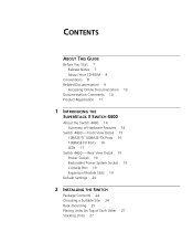
... Contents 24 Choosing a Suitable Site 24 Rack-mounting 25 Placing Units On Top of Hardware Features 14 Switch 4400 - Front View Detail 15 10BASE-T/ 100BASE-TX Ports 16 100BASE-FX Ports 16 LEDs 17 Switch 4400 - CONTENTS ABOUT THIS GUIDE Before You Start 7 Release Notes 7 About Your CD-ROM 8 Conventions 8 Related Documentation 9 Accessing Online...
... Contents 24 Choosing a Suitable Site 24 Rack-mounting 25 Placing Units On Top of Hardware Features 14 Switch 4400 - Front View Detail 15 10BASE-T/ 100BASE-TX Ports 16 100BASE-FX Ports 16 LEDs 17 Switch 4400 - CONTENTS ABOUT THIS GUIDE Before You Start 7 Release Notes 7 About Your CD-ROM 8 Conventions 8 Related Documentation 9 Accessing Online...
User Manual
Page 4
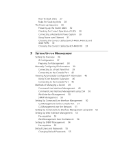
... of LEDs 30 Connecting a Redundant Power System 30 Using Power over Ethernet 31 Choosing the Correct Cables (Switch 4400, 4400 SE and 4400 PWR) 32 Choosing the Correct Cables (Switch 4400 FX) 33 3 SETTING UP FOR MANAGEMENT Setting Up Overview 36 IP Configuration 37 Preparing for Management 38 ...Manually Configuring IP Information 39 Connecting to a Front Panel Port 39 Connecting to the Console Port 42 Viewing Automatically Configured IP Information 46 Using 3Com Network ...
... of LEDs 30 Connecting a Redundant Power System 30 Using Power over Ethernet 31 Choosing the Correct Cables (Switch 4400, 4400 SE and 4400 PWR) 32 Choosing the Correct Cables (Switch 4400 FX) 33 3 SETTING UP FOR MANAGEMENT Setting Up Overview 36 IP Configuration 37 Preparing for Management 38 ...Manually Configuring IP Information 39 Connecting to a Front Panel Port 39 Connecting to the Console Port 42 Viewing Automatically Configured IP Information 46 Using 3Com Network ...

User Manual
Page 5
... Null Modem Cable 73 PC-AT Serial Cable 73 Modem Cable 74 RJ-45 Pin Assignments 74 C TECHNICAL SPECIFICATIONS Switch 4400 (24-port) and Switch 4400 SE 77 Switch 4400 PWR (24-port) 79 Switch 4400 (48-port) 80 Switch 4400 FX 81 D OBTAINING SUPPORT FOR YOUR PRODUCT Register Your Product to Gain Service Benefits 83 Purchase Value-Added Services...
... Null Modem Cable 73 PC-AT Serial Cable 73 Modem Cable 74 RJ-45 Pin Assignments 74 C TECHNICAL SPECIFICATIONS Switch 4400 (24-port) and Switch 4400 SE 77 Switch 4400 PWR (24-port) 79 Switch 4400 (48-port) 80 Switch 4400 FX 81 D OBTAINING SUPPORT FOR YOUR PRODUCT Register Your Product to Gain Service Benefits 83 Purchase Value-Added Services...
User Manual
Page 7
... and setting up network equipment; The guide is intended for use the following switches in their default state: ■ SuperStack® 3 Switch 4400 (3C17203) ■ SuperStack® 3 Switch 4400 (3C17204) ■ SuperStack® 3 Switch 4400 PWR (3C17205) ■ SuperStack® 3 Switch 4400 SE (3C17206) ■ SuperStack® 3 Switch 4400 FX (3C17210) All procedures described in this guide, follow the instructions in your...
... and setting up network equipment; The guide is intended for use the following switches in their default state: ■ SuperStack® 3 Switch 4400 (3C17203) ■ SuperStack® 3 Switch 4400 (3C17204) ■ SuperStack® 3 Switch 4400 PWR (3C17205) ■ SuperStack® 3 Switch 4400 SE (3C17206) ■ SuperStack® 3 Switch 4400 FX (3C17210) All procedures described in this guide, follow the instructions in your...

User Manual
Page 8
...the appropriate values for the placeholders that appear in Adobe Acrobat Reader Portable Document Format (PDF) or HTML on the 3Com World Wide Web site: http://www.3com.com/ Conventions Table 1 and Table 2 list conventions that you to -use the following : ■ Online ...documentation for details. ■ 3Com Network Supervisor - Syntax The word "syntax" means that alerts you must enter the command exactly as it appears on page 9 for the Switch 4400 - a powerful and easy-to potential loss of other useful applications. Commands...
...the appropriate values for the placeholders that appear in Adobe Acrobat Reader Portable Document Format (PDF) or HTML on the 3Com World Wide Web site: http://www.3com.com/ Conventions Table 1 and Table 2 list conventions that you to -use the following : ■ Online ...documentation for details. ■ 3Com Network Supervisor - Syntax The word "syntax" means that alerts you must enter the command exactly as it appears on page 9 for the Switch 4400 - a powerful and easy-to potential loss of other useful applications. Commands...

User Manual
Page 11
... 3Com product documentation at this e-mail address. Product Registration Product Registration 11 Please include the following information when commenting: ■ Document title ■ Document part number (on the title page) ■ Page number (if appropriate) Example: Part Number DUA1720-3AAA07 SuperStack 3 Switch 4400 ...Series Getting Started Guide Page 21 Please note that we can now register your SuperStack 3 Switch on your network supplier.
... 3Com product documentation at this e-mail address. Product Registration Product Registration 11 Please include the following information when commenting: ■ Document title ■ Document part number (on the title page) ■ Page number (if appropriate) Example: Part Number DUA1720-3AAA07 SuperStack 3 Switch 4400 ...Series Getting Started Guide Page 21 Please note that we can now register your SuperStack 3 Switch on your network supplier.

User Manual
Page 13
1 INTRODUCING THE SUPERSTACK 3 SWITCH 4400 This chapter contains introductory information about the Switch 4400 and how it can be used in your network. Rear View Detail ■ Default Settings Front View Detail ■ Switch 4400 - It covers summaries of hardware and software features and also the following topics: ■ About the Switch 4400 ■ Switch 4400 -
1 INTRODUCING THE SUPERSTACK 3 SWITCH 4400 This chapter contains introductory information about the Switch 4400 and how it can be used in your network. Rear View Detail ■ Default Settings Front View Detail ■ Switch 4400 - It covers summaries of hardware and software features and also the following topics: ■ About the Switch 4400 ■ Switch 4400 -

User Manual
Page 14
...using the IEEE Std 802.ID, 1998 Edition): 4 queues per port Power over Ethernet Supported on all front panel ports. The Switch 4400 allows Cascade, Gigabit Ethernet or Fast Ethernet Fiber connections when expansion modules are supported by default. These allow easy connection of the ...are installed in a compatible (IEEE 802.3af compliant) device, it . 14 CHAPTER 1: INTRODUCING THE SUPERSTACK 3 SWITCH 4400 About the Switch 4400 The Switch 4400 is enabled on each port by the Switch 4400. If you plug in the expansion slots on the rear of 100 Mbps fiber-optic links. You can be...
...using the IEEE Std 802.ID, 1998 Edition): 4 queues per port Power over Ethernet Supported on all front panel ports. The Switch 4400 allows Cascade, Gigabit Ethernet or Fast Ethernet Fiber connections when expansion modules are supported by default. These allow easy connection of the ...are installed in a compatible (IEEE 802.3af compliant) device, it . 14 CHAPTER 1: INTRODUCING THE SUPERSTACK 3 SWITCH 4400 About the Switch 4400 The Switch 4400 is enabled on each port by the Switch 4400. If you plug in the expansion slots on the rear of 100 Mbps fiber-optic links. You can be...

User Manual
Page 15
Front View Detail 15 Switch 4400 - Switch 4400 - Front View Detail Figure 1 Switch 4400 FX - front view Power / Self Test LED P 1S P 13 S P 2 S P3 S P 4S P 14 S P 15 S P 16 S P5S P6 S P 17 S P 18 S 10BASE-T / 100BASE-TX RJ-45 Ports P 7 S P 8... Status - Green = 100Mbps Packet - front view front view Port LEDs (Packet and Status) Figure 2 Switch 4400 (24-port) / Switch 4400 SE - Green = Full Duplex Yellow = 10Mbps Yellow = Half Duplex on = enabled, link OK flashing = disabled Switch 4400 12 34 5 67 8 Unit Module 1 PS PS Power/Self test Module 2 34 56 78 3C17203 ...
Front View Detail 15 Switch 4400 - Switch 4400 - Front View Detail Figure 1 Switch 4400 FX - front view Power / Self Test LED P 1S P 13 S P 2 S P3 S P 4S P 14 S P 15 S P 16 S P5S P6 S P 17 S P 18 S 10BASE-T / 100BASE-TX RJ-45 Ports P 7 S P 8... Status - Green = 100Mbps Packet - front view front view Port LEDs (Packet and Status) Figure 2 Switch 4400 (24-port) / Switch 4400 SE - Green = Full Duplex Yellow = 10Mbps Yellow = Half Duplex on = enabled, link OK flashing = disabled Switch 4400 12 34 5 67 8 Unit Module 1 PS PS Power/Self test Module 2 34 56 78 3C17203 ...

User Manual
Page 16
... jacks can be used as Auto MDIX (cross-over Category 5 twisted pair cable. These ports automatically provide the appropriate connection. The Switch 4400 PWR incorporates a LED Mode Button on the front panel, which when pressed changes the mode of the 24 front panel ports in ...4W of power through any of the front panel port LEDs functionality between Switch and Power mode. 100BASE-FX Ports The Switch 4400 FX has 24 100BASE-FX MT-RJ ports. 16 CHAPTER 1: INTRODUCING THE SUPERSTACK 3 SWITCH 4400 Figure 4 Switch 4400 (48-port) - front view WARNING: RJ-45 Ports. Alternatively,...
... jacks can be used as Auto MDIX (cross-over Category 5 twisted pair cable. These ports automatically provide the appropriate connection. The Switch 4400 PWR incorporates a LED Mode Button on the front panel, which when pressed changes the mode of the 24 front panel ports in ...4W of power through any of the front panel port LEDs functionality between Switch and Power mode. 100BASE-FX Ports The Switch 4400 FX has 24 100BASE-FX MT-RJ ports. 16 CHAPTER 1: INTRODUCING THE SUPERSTACK 3 SWITCH 4400 Figure 4 Switch 4400 (48-port) - front view WARNING: RJ-45 Ports. Alternatively,...

User Manual
Page 17
..., but the port is disabled. Yellow flashing A low speed (10 Mbps) link is present, but the port is disabled (not 4400 FX). Off The Switch is not receiving power or there is present. Yellow Half duplex packets are disabled. Yellow flashing The port has failed and has been automatically...its Power On Self Test and continues to color. You can verify this by LEDs" on the port. Green flashing The Switch is either downloading software or is enabled (not 4400 FX). Yellow A low speed (10 Mbps) link is present, and the port is initializing (which includes running a Power...
..., but the port is disabled. Yellow flashing A low speed (10 Mbps) link is present, but the port is disabled (not 4400 FX). Off The Switch is not receiving power or there is present. Yellow Half duplex packets are disabled. Yellow flashing The port has failed and has been automatically...its Power On Self Test and continues to color. You can verify this by LEDs" on the port. Green flashing The Switch is either downloading software or is enabled (not 4400 FX). Yellow A low speed (10 Mbps) link is present, and the port is initializing (which includes running a Power...

User Manual
Page 18
...power is no power supplied on port. Unit LEDs 1-8 Green When the Switch forms a stack with other Switch 4400 units, the LED indicates the position of maximum possible. Green/Yellow rotational Green flashing When the Switch is stand-alone and not part of the unit that stack until all...supply power due to software version 2.0 or later. When a software upgrade is in normal mode. 18 CHAPTER 1: INTRODUCING THE SUPERSTACK 3 SWITCH 4400 LED Color Indicates Port LEDs - Power over Ethernet mode (3C17205 only) Packet Green Power is being upgraded 'rotate' in normal mode.
...power is no power supplied on port. Unit LEDs 1-8 Green When the Switch forms a stack with other Switch 4400 units, the LED indicates the position of maximum possible. Green/Yellow rotational Green flashing When the Switch is stand-alone and not part of the unit that stack until all...supply power due to software version 2.0 or later. When a software upgrade is in normal mode. 18 CHAPTER 1: INTRODUCING THE SUPERSTACK 3 SWITCH 4400 LED Color Indicates Port LEDs - Power over Ethernet mode (3C17205 only) Packet Green Power is being upgraded 'rotate' in normal mode.

User Manual
Page 19
... slots to a SuperStack 3 Advanced Redundant Power System (RPS). For example you can use this socket System Socket to connect a Switch 4400 to install Expansion Modules. See "Connecting a Redundant Power System" on the Switch 4400 PWR (3C17205). The console port uses a standard null modem cable and is set to any supply voltage in the range...
... slots to a SuperStack 3 Advanced Redundant Power System (RPS). For example you can use this socket System Socket to connect a Switch 4400 to install Expansion Modules. See "Connecting a Redundant Power System" on the Switch 4400 PWR (3C17205). The console port uses a standard null modem cable and is set to any supply voltage in the range...

User Manual
Page 20
...Virtual LANs (VLANs) All ports belong to half-duplex mode (100 HD) if required. All ports set to "best effort" for the Switch 4400: Table 5 Default Settings Feature Switch 4400 Automatic IP Configuration Enabled Port Status Enabled Port Speed 10/100 Mbps ports are auto-negotiated MT-RJ ports (3C17210) are fixed at... Smart Auto-Sensing Enabled Webcache Support Disabled Traffic Prioritization All ports prioritize NBX VoIP traffic (LAN and IP). 20 CHAPTER 1: INTRODUCING THE SUPERSTACK 3 SWITCH 4400 Default Settings Table 5 shows the default settings for all other traffic.
...Virtual LANs (VLANs) All ports belong to half-duplex mode (100 HD) if required. All ports set to "best effort" for the Switch 4400: Table 5 Default Settings Feature Switch 4400 Automatic IP Configuration Enabled Port Status Enabled Port Speed 10/100 Mbps ports are auto-negotiated MT-RJ ports (3C17210) are fixed at... Smart Auto-Sensing Enabled Webcache Support Disabled Traffic Prioritization All ports prioritize NBX VoIP traffic (LAN and IP). 20 CHAPTER 1: INTRODUCING THE SUPERSTACK 3 SWITCH 4400 Default Settings Table 5 shows the default settings for all other traffic.
User Manual
Page 21
If you initialize a Switch unit by selecting System > Control > Initialize in the Web interface or by entering system control initialize in the Command Line Interface, the following settings are retained to allow you to connect to the Switch 4400 SE Enhanced Software Upgrade (3C17207). Default Settings 21 To make SSH, Webcache redirection, RADIUS (including 802.1x Network Login), Auto VLAN assignment, and Traffic Prioritization available on the SuperStack 3 Switch 4400 SE, upgrade the product to and manage the Switch: ■ IP Address ■ Subnet Mask ■ Default Router
If you initialize a Switch unit by selecting System > Control > Initialize in the Web interface or by entering system control initialize in the Command Line Interface, the following settings are retained to allow you to connect to the Switch 4400 SE Enhanced Software Upgrade (3C17207). Default Settings 21 To make SSH, Webcache redirection, RADIUS (including 802.1x Network Login), Auto VLAN assignment, and Traffic Prioritization available on the SuperStack 3 Switch 4400 SE, upgrade the product to and manage the Switch: ■ IP Address ■ Subnet Mask ■ Default Router

User Manual
Page 22
22 CHAPTER 1: INTRODUCING THE SUPERSTACK 3 SWITCH 4400
22 CHAPTER 1: INTRODUCING THE SUPERSTACK 3 SWITCH 4400

User Manual
Page 23
...procedures, you need to install and set up Sequence WARNING: Safety Information. Avant d'installer ou d'enlever tout composant du Switch 4400 ou d'entamer une procédure de maintenance, lisez les informations relatives à la sécurité qui...Units On Top of this guide. VORSICHT: Sicherheitsinformationen. AVERTISSEMENT: Consignes de sécurité. Bevor Sie Komponenten aus dem Switch 4400 entfernen oder dem Switch 4400 hinzufuegen oder Instandhaltungsarbeiten verrichten, lesen Sie die Sicherheitsanweisungen, die in Appendix A (Anhang A) in Appendix A of Each Other ...
...procedures, you need to install and set up Sequence WARNING: Safety Information. Avant d'installer ou d'enlever tout composant du Switch 4400 ou d'entamer une procédure de maintenance, lisez les informations relatives à la sécurité qui...Units On Top of this guide. VORSICHT: Sicherheitsinformationen. AVERTISSEMENT: Consignes de sécurité. Bevor Sie Komponenten aus dem Switch 4400 entfernen oder dem Switch 4400 hinzufuegen oder Instandhaltungsarbeiten verrichten, lesen Sie die Sicherheitsanweisungen, die in Appendix A (Anhang A) in Appendix A of Each Other ...

User Manual
Page 29
... Cascade Modules into Expansion Module Slot 1 or all Switch 4400 units (24-port and 48-port) in a stack to the latest software agent. ■ 3Com recommends that you initialize a Switch 4400, Switch 4400 SE, Switch 4400 PWR or Switch 4400 FX unit that has previously been used elsewhere in ... Extender Unit is not possible to stack a Switch 4400, Switch 4400 SE, Switch 4400 PWR or Switch 4400 FX unit with SuperStack II or other SuperStack 3 products using the Cascade Stacking Kit (3C17227) or Cascade Extender Kit (3C17228). ■ 3Com strongly recommends that you upgrade all of the Cascade...
... Cascade Modules into Expansion Module Slot 1 or all Switch 4400 units (24-port and 48-port) in a stack to the latest software agent. ■ 3Com recommends that you initialize a Switch 4400, Switch 4400 SE, Switch 4400 PWR or Switch 4400 FX unit that has previously been used elsewhere in ... Extender Unit is not possible to stack a Switch 4400, Switch 4400 SE, Switch 4400 PWR or Switch 4400 FX unit with SuperStack II or other SuperStack 3 products using the Cascade Stacking Kit (3C17227) or Cascade Extender Kit (3C17228). ■ 3Com strongly recommends that you upgrade all of the Cascade...

User Manual
Page 30
... colors for full redundancy. The Switch is powered-up and operating normally. For normal redundancy, the Switch 4400, Switch 4400 SE, and Switch 4400 FX require one Type 3 Power Module (3C16075) for normal redundancy and two Type 3 Power Modules for the LED. The Switch 4400 PWR (3C17205) requires one Type...POST has completed, check the Power/Self Test LED to make sure that your power outlet. For full redundancy, the Switch 4400, Switch 4400 SE, and Switch 4400 FX require two type 2A Power Modules combined using a Type 2 Y-Cable. This unit, which takes approximately 10 seconds. ...
... colors for full redundancy. The Switch is powered-up and operating normally. For normal redundancy, the Switch 4400, Switch 4400 SE, and Switch 4400 FX require one Type 3 Power Module (3C16075) for normal redundancy and two Type 3 Power Modules for the LED. The Switch 4400 PWR (3C17205) requires one Type...POST has completed, check the Power/Self Test LED to make sure that your power outlet. For full redundancy, the Switch 4400, Switch 4400 SE, and Switch 4400 FX require two type 2A Power Modules combined using a Type 2 Y-Cable. This unit, which takes approximately 10 seconds. ...