
User Manual
Page 1
DUA1720-3AAA07 Published March 2004 SuperStack® 3 Switch 4400 Series Getting Started Guide Switch 4400 (3C17203) Switch 4400 (3C17204) Switch 4400 PWR (3C17205) Switch 4400 SE (3C17206) Switch 4400 FX (3C17210) http://www.3com.com/ Part No.
DUA1720-3AAA07 Published March 2004 SuperStack® 3 Switch 4400 Series Getting Started Guide Switch 4400 (3C17203) Switch 4400 (3C17204) Switch 4400 PWR (3C17205) Switch 4400 SE (3C17206) Switch 4400 FX (3C17210) http://www.3com.com/ Part No.

User Manual
Page 2
...is environmentally-friendly, and the inks are associated. The varnish is a registered trademark in the United States and other countries. 3Com, the 3Com logo and SuperStack are registered trademarks of the Institute of the respective companies with which they are vegetable-based with limited rights...any means or used to make any derivative work (such as translation, transformation, or adaptation) without written permission from 3Com Corporation. 3Com Corporation reserves the right to revise this documentation and to make improvements or changes in the product(s) and/or the program...
...is environmentally-friendly, and the inks are associated. The varnish is a registered trademark in the United States and other countries. 3Com, the 3Com logo and SuperStack are registered trademarks of the Institute of the respective companies with which they are vegetable-based with limited rights...any means or used to make any derivative work (such as translation, transformation, or adaptation) without written permission from 3Com Corporation. 3Com Corporation reserves the right to revise this documentation and to make improvements or changes in the product(s) and/or the program...
User Manual
Page 3
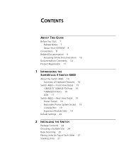
Front View Detail 15 10BASE-T/ 100BASE-TX Ports 16 100BASE-FX Ports 16 LEDs 17 Switch 4400 - Rear View Detail 19 Power Socket 19 Redundant Power System Socket 19 Console Port 19 Expansion Module Slots 19 Default Settings 20 2 INSTALLING THE SWITCH Package Contents 24 Choosing a Suitable Site 24 Rack-mounting 25 Placing Units On Top of Hardware Features 14 Switch 4400 - CONTENTS ABOUT THIS GUIDE Before You Start 7 Release Notes 7 About Your CD-ROM 8 Conventions 8 Related Documentation 9 Accessing Online Documentation 10 Documentation Comments 10 Product Registration 11 1 INTRODUCING THE ...
Front View Detail 15 10BASE-T/ 100BASE-TX Ports 16 100BASE-FX Ports 16 LEDs 17 Switch 4400 - Rear View Detail 19 Power Socket 19 Redundant Power System Socket 19 Console Port 19 Expansion Module Slots 19 Default Settings 20 2 INSTALLING THE SWITCH Package Contents 24 Choosing a Suitable Site 24 Rack-mounting 25 Placing Units On Top of Hardware Features 14 Switch 4400 - CONTENTS ABOUT THIS GUIDE Before You Start 7 Release Notes 7 About Your CD-ROM 8 Conventions 8 Related Documentation 9 Accessing Online Documentation 10 Documentation Comments 10 Product Registration 11 1 INTRODUCING THE ...
User Manual
Page 4
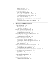
... 38 Manually Configuring IP Information 39 Connecting to a Front Panel Port 39 Connecting to the Console Port 42 Viewing Automatically Configured IP Information 46 Using 3Com Network Supervisor 46 Connecting to the Console Port 46 Methods of Managing a Switch 49 Command Line Interface Management 49 Command Line Interface Management using SSH...
... 38 Manually Configuring IP Information 39 Connecting to a Front Panel Port 39 Connecting to the Console Port 42 Viewing Automatically Configured IP Information 46 Using 3Com Network Supervisor 46 Connecting to the Console Port 46 Methods of Managing a Switch 49 Command Line Interface Management 49 Command Line Interface Management using SSH...

User Manual
Page 5
Japan 65 Important Safety Information 66 L'information de Sécurité Importante 68 Wichtige Sicherheitsinformationen 70 B PIN-OUTS Null Modem Cable 73 PC-AT Serial Cable 73 Modem Cable 74 RJ-45 Pin Assignments 74 C TECHNICAL SPECIFICATIONS Switch 4400 (24-port) and Switch 4400 SE 77 Switch 4400 PWR (24-port) 79 Switch 4400 (48-port) 80 Switch 4400 FX 81 D OBTAINING SUPPORT FOR YOUR PRODUCT Register Your Product to Gain Service Benefits 83 Purchase Value-Added Services 83 Troubleshoot Online 83 Access Software Downloads 84 Contact Us 84 Telephone Technical Support and Repair 84 4 ...
Japan 65 Important Safety Information 66 L'information de Sécurité Importante 68 Wichtige Sicherheitsinformationen 70 B PIN-OUTS Null Modem Cable 73 PC-AT Serial Cable 73 Modem Cable 74 RJ-45 Pin Assignments 74 C TECHNICAL SPECIFICATIONS Switch 4400 (24-port) and Switch 4400 SE 77 Switch 4400 PWR (24-port) 79 Switch 4400 (48-port) 80 Switch 4400 FX 81 D OBTAINING SUPPORT FOR YOUR PRODUCT Register Your Product to Gain Service Benefits 83 Purchase Value-Added Services 83 Troubleshoot Online 83 Access Software Downloads 84 Contact Us 84 Telephone Technical Support and Repair 84 4 ...

User Manual
Page 6
INDEX REGULATORY NOTICES
INDEX REGULATORY NOTICES
User Manual
Page 7
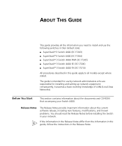
... Networks). The guide is intended for use the following switches in their default state: ■ SuperStack® 3 Switch 4400 (3C17203) ■ SuperStack® 3 Switch 4400 (3C17204) ■ SuperStack® 3 Switch 4400 PWR (3C17205) ■ SuperStack® 3 Switch 4400 SE (3C17206) ■ SuperStack® 3 Switch 4400 FX (3C17210) All procedures described in...
... Networks). The guide is intended for use the following switches in their default state: ■ SuperStack® 3 Switch 4400 (3C17203) ■ SuperStack® 3 Switch 4400 (3C17204) ■ SuperStack® 3 Switch 4400 PWR (3C17205) ■ SuperStack® 3 Switch 4400 SE (3C17206) ■ SuperStack® 3 Switch 4400 FX (3C17210) All procedures described in...

User Manual
Page 8
...this guide. Most user guides and release notes are used throughout this example, you to Related Documentation on the 3Com World Wide Web site: http://www.3com.com/ Conventions Table 1 and Table 2 list conventions that appear in angle brackets. Commands appear in Adobe Acrobat...exactly as it appears on the screen. Syntax The word "syntax" means that you must supply a password for details. ■ 3Com Network Supervisor - refer to potential personal injury Table 2 Text Conventions Convention Description Screen displays This typeface represents information as shown and then...
...this guide. Most user guides and release notes are used throughout this example, you to Related Documentation on the 3Com World Wide Web site: http://www.3com.com/ Conventions Table 1 and Table 2 list conventions that appear in angle brackets. Commands appear in Adobe Acrobat...exactly as it appears on the screen. Syntax The word "syntax" means that you must supply a password for details. ■ 3Com Network Supervisor - refer to potential personal injury Table 2 Text Conventions Convention Description Screen displays This typeface represents information as shown and then...

User Manual
Page 9
Examples: From the Help menu, select Contents. Click OK. If you must type something, and then press Return or Enter. In addition to this guide, you must press two or more keys simultaneously, the key names are used to manage the Switch. It is defined in the text. ■ Identify menu names, menu commands, and software button names. Do not press Return or Enter when an instruction simply says "type." Example: Words in italics Press Ctrl+Alt+Del Italics are linked with a plus sign (+). It is supplied in HTML format on the CD-ROM that enable you to optimize your ...
Examples: From the Help menu, select Contents. Click OK. If you must type something, and then press Return or Enter. In addition to this guide, you must press two or more keys simultaneously, the key names are used to manage the Switch. It is defined in the text. ■ Identify menu names, menu commands, and software button names. Do not press Return or Enter when an instruction simply says "type." Example: Words in italics Press Ctrl+Alt+Del Italics are linked with a plus sign (+). It is supplied in HTML format on the CD-ROM that enable you to optimize your ...

User Manual
Page 10
10 ABOUT THIS GUIDE ■ Release Notes These notes provide information about this document to 3Com at: pddtechpubs_comments@3com.com Documentation Comments Your suggestions are other publications you may find useful, such as a whole to maintain the structure of the files....the documentation on the CD-ROM supplied with your Switch. If the online documentation is stored in the Docs/implementation directory of the CD-ROM. 3Com recommends that accompanies the Switch. The documentation is accessed using the contents.htm file. ■ The PDF Implementation Guide is to be accessed ...
10 ABOUT THIS GUIDE ■ Release Notes These notes provide information about this document to 3Com at: pddtechpubs_comments@3com.com Documentation Comments Your suggestions are other publications you may find useful, such as a whole to maintain the structure of the files....the documentation on the CD-ROM supplied with your Switch. If the online documentation is stored in the Docs/implementation directory of the CD-ROM. 3Com recommends that accompanies the Switch. The documentation is accessed using the contents.htm file. ■ The PDF Implementation Guide is to be accessed ...

User Manual
Page 11
Questions related to technical support or sales should be directed in the first instance to your product: http://www.3com.com/register You can only respond to comments and questions about 3Com product documentation at this e-mail address. Product Registration Product Registration 11 Please include the following information when commenting: ■ Document ...Part Number DUA1720-3AAA07 SuperStack 3 Switch 4400 Series Getting Started Guide Page 21 Please note that we can now register your SuperStack 3 Switch on the 3Com web site to receive up-to-date information on your network supplier.
Questions related to technical support or sales should be directed in the first instance to your product: http://www.3com.com/register You can only respond to comments and questions about 3Com product documentation at this e-mail address. Product Registration Product Registration 11 Please include the following information when commenting: ■ Document ...Part Number DUA1720-3AAA07 SuperStack 3 Switch 4400 Series Getting Started Guide Page 21 Please note that we can now register your SuperStack 3 Switch on the 3Com web site to receive up-to-date information on your network supplier.

User Manual
Page 12
12 ABOUT THIS GUIDE
12 ABOUT THIS GUIDE

User Manual
Page 13
It covers summaries of hardware and software features and also the following topics: ■ About the Switch 4400 ■ Switch 4400 - Front View Detail ■ Switch 4400 - Rear View Detail ■ Default Settings 1 INTRODUCING THE SUPERSTACK 3 SWITCH 4400 This chapter contains introductory information about the Switch 4400 and how it can be used in your network.
It covers summaries of hardware and software features and also the following topics: ■ About the Switch 4400 ■ Switch 4400 - Front View Detail ■ Switch 4400 - Rear View Detail ■ Default Settings 1 INTRODUCING THE SUPERSTACK 3 SWITCH 4400 This chapter contains introductory information about the Switch 4400 and how it can be used in your network.

User Manual
Page 14
If you plug in a compatible (IEEE 802.3af compliant) device, it . The Switch 4400 FX (3C17210) has 24 100BASE-FX MT-RJ ports. Ethernet and Fast Ethernet Auto-negotiating 10BASE-T/100BASE-TX ports or Ports 100BASE-FX ports (3C17210) RPS Support Connects to SuperStack 3 Advanced Redundant Power System (ARPS) (3C16071B) Mounting 19-inch rack or stand-alone mounting Stacking All Switch units in the expansion slots on each port by the Switch 4400. The Switch 4400 PWR (3C17205) supports Power over Ethernet on all front panel ports. Table 3 Hardware features Feature Switch 4400 ...
If you plug in a compatible (IEEE 802.3af compliant) device, it . The Switch 4400 FX (3C17210) has 24 100BASE-FX MT-RJ ports. Ethernet and Fast Ethernet Auto-negotiating 10BASE-T/100BASE-TX ports or Ports 100BASE-FX ports (3C17210) RPS Support Connects to SuperStack 3 Advanced Redundant Power System (ARPS) (3C16071B) Mounting 19-inch rack or stand-alone mounting Stacking All Switch units in the expansion slots on each port by the Switch 4400. The Switch 4400 PWR (3C17205) supports Power over Ethernet on all front panel ports. Table 3 Hardware features Feature Switch 4400 ...

User Manual
Page 15
Front View Detail 15 Switch 4400 - front view Port LEDs (Packet and Status) Figure 2 Switch 4400 (24-port) / Switch 4400 SE - Green = Full Duplex Yellow = 10Mbps Yellow = Half Duplex on = enabled, link OK flashing = disabled Switch 4400 12 34 5 67 8 Unit Module 1 PS PS Power/Self test Module 2 34 56 78 3C17203 SuperStack© 3 Unit LEDs Module LEDs (Packet and Status) Figure 3 Switch 4400 PWR - front view Power / Self Test LED P 1S P 13 S P 2 S P3 S P 4S P 14 S P 15 S P 16 S P5S P6 S P 17 S P 18 S 10BASE-T / 100BASE-TX RJ-45 Ports P 7 S P 8 S P 9 S P 10 S P 11 S P 12 S ...
Front View Detail 15 Switch 4400 - front view Port LEDs (Packet and Status) Figure 2 Switch 4400 (24-port) / Switch 4400 SE - Green = Full Duplex Yellow = 10Mbps Yellow = Half Duplex on = enabled, link OK flashing = disabled Switch 4400 12 34 5 67 8 Unit Module 1 PS PS Power/Self test Module 2 34 56 78 3C17203 SuperStack© 3 Unit LEDs Module LEDs (Packet and Status) Figure 3 Switch 4400 PWR - front view Power / Self Test LED P 1S P 13 S P 2 S P3 S P 4S P 14 S P 15 S P 16 S P5S P6 S P 17 S P 18 S 10BASE-T / 100BASE-TX RJ-45 Ports P 7 S P 8 S P 9 S P 10 S P 11 S P 12 S ...

User Manual
Page 16
front view WARNING: RJ-45 Ports. Either shielded or unshielded data cables with shielded or unshielded jacks can be used as Auto MDIX (cross-over Category 5 twisted pair cable. These ports automatically provide the appropriate connection. These are shielded RJ-45 data sockets. They use standard multi-mode fiber-optic cable of up to 15.4W of power through any of the front panel port LEDs functionality between Switch and Power mode. 100BASE-FX Ports The Switch 4400 FX has 24 100BASE-FX MT-RJ ports. The Switch 4400 PWR incorporates a LED Mode Button on the front panel,...
front view WARNING: RJ-45 Ports. Either shielded or unshielded data cables with shielded or unshielded jacks can be used as Auto MDIX (cross-over Category 5 twisted pair cable. These ports automatically provide the appropriate connection. These are shielded RJ-45 data sockets. They use standard multi-mode fiber-optic cable of up to 15.4W of power through any of the front panel port LEDs functionality between Switch and Power mode. 100BASE-FX Ports The Switch 4400 FX has 24 100BASE-FX MT-RJ ports. The Switch 4400 PWR incorporates a LED Mode Button on the front panel,...

User Manual
Page 17
For information on using the LEDs for problem solving, see "Solving Problems Indicated by checking that allows both the transmit and the receive fibers to operate normally even if one or more ports are being transmitted/received on the port. Table 4 LED behavior LED Color Indicates Power/Self Test LED Green The Switch is a fault with the Power Supply Unit. Off The Switch is not receiving power or there is powered-up and operating normally. Yellow flashing A low speed (10 Mbps) link is present, but the port is disabled (not 4400 FX). You can verify this by LEDs" ...
For information on using the LEDs for problem solving, see "Solving Problems Indicated by checking that allows both the transmit and the receive fibers to operate normally even if one or more ports are being transmitted/received on the port. Table 4 LED behavior LED Color Indicates Power/Self Test LED Green The Switch is a fault with the Power Supply Unit. Off The Switch is not receiving power or there is powered-up and operating normally. Yellow flashing A low speed (10 Mbps) link is present, but the port is disabled (not 4400 FX). You can verify this by LEDs" ...

User Manual
Page 18
Yellow Power over Ethernet mode (3C17205 only) Packet Green Power is being upgraded 'rotate' in normal mode. Status Refer to operate normally even if one or more ports has a Power over budget (denyLowPriority MIB state). Yellow flashing The module has failed and has been automatically disabled. (fast) The Switch passes its Power On Self Test and continues to the user documentation accompanying the module, if installed. The Switch physically forms a stack with other Switch 4400 units, but cannot be managed as a percentage of that is stand-alone and not part of the unit that...
Yellow Power over Ethernet mode (3C17205 only) Packet Green Power is being upgraded 'rotate' in normal mode. Status Refer to operate normally even if one or more ports has a Power over budget (denyLowPriority MIB state). Yellow flashing The module has failed and has been automatically disabled. (fast) The Switch passes its Power On Self Test and continues to the user documentation accompanying the module, if installed. The Switch physically forms a stack with other Switch 4400 units, but cannot be managed as a percentage of that is stand-alone and not part of the unit that...

User Manual
Page 19
rear view View Detail Power Socket The Switch automatically adjusts its power setting to install Expansion Modules. See "Connecting a Redundant Power System" on the Switch 4400 PWR (3C17205). Expansion Module Slots You can use this socket System Socket to connect a Switch 4400 to be stacked with a suitable tool. Contact your Switch. Redundant Power To protect against internal power supply failure, you can install a Cascade module to enable the Switch to a SuperStack 3 Advanced Redundant Power System (RPS). For example you to connect a terminal and perform remote or local ...
rear view View Detail Power Socket The Switch automatically adjusts its power setting to install Expansion Modules. See "Connecting a Redundant Power System" on the Switch 4400 PWR (3C17205). Expansion Module Slots You can use this socket System Socket to connect a Switch 4400 to be stacked with a suitable tool. Contact your Switch. Redundant Power To protect against internal power supply failure, you can install a Cascade module to enable the Switch to a SuperStack 3 Advanced Redundant Power System (RPS). For example you to connect a terminal and perform remote or local ...

User Manual
Page 20
All ports set to half-duplex mode (100 HD) if required. Port Security Disabled per port IP Multicast Filtering Filtering enabled Rapid Spanning Tree Protocol Enabled Fast Start ■ Enabled on front panel ports ■ Disabled on rear panel port RMON Alarm Enabled Smart Auto-Sensing Enabled Webcache Support Disabled Traffic Prioritization All ports prioritize NBX VoIP traffic (LAN and IP). Power over Ethernet Enabled (3C17205 only) Flow Control ■ Enabled in half-duplex mode ■ Auto-negotiated in full-duplex mode Broadcast Storm Control Enabled Virtual ...
All ports set to half-duplex mode (100 HD) if required. Port Security Disabled per port IP Multicast Filtering Filtering enabled Rapid Spanning Tree Protocol Enabled Fast Start ■ Enabled on front panel ports ■ Disabled on rear panel port RMON Alarm Enabled Smart Auto-Sensing Enabled Webcache Support Disabled Traffic Prioritization All ports prioritize NBX VoIP traffic (LAN and IP). Power over Ethernet Enabled (3C17205 only) Flow Control ■ Enabled in half-duplex mode ■ Auto-negotiated in full-duplex mode Broadcast Storm Control Enabled Virtual ...