User Guide
Page 12
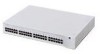
12 CHAPTER 1: 3COM ETHERNET POWER SOURCE OVERVIEW 10/100BASE-TX Data and Power Output Ports The EPS output ports (top row) carry two kinds of accepting power via its Ethernet connection. For example, if the yellow LED for any port is ON, the EPS is not supplying power to that port/device, which may... a problem. For information on and a device is drawing power from the switch or hub to draw too much power from the port. On Off I DC power on , but no device cable is plugged into the port is off the port power. The EPS has shut off . Table 3 LED Behavior ...
12 CHAPTER 1: 3COM ETHERNET POWER SOURCE OVERVIEW 10/100BASE-TX Data and Power Output Ports The EPS output ports (top row) carry two kinds of accepting power via its Ethernet connection. For example, if the yellow LED for any port is ON, the EPS is not supplying power to that port/device, which may... a problem. For information on and a device is drawing power from the switch or hub to draw too much power from the port. On Off I DC power on , but no device cable is plugged into the port is off the port power. The EPS has shut off . Table 3 LED Behavior ...

User Guide
Page 15
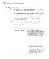
... a short UTP cable of 1 to 2 m (6 to 7 ft.) from the switch or hub to the EPS and a longer UTP cable of 1 to 90 m (3 to the powered device such as the NBX Business Telephone or a 3Com wireless access point. If an external DC supply is 100 m (328 ft.) using Category 5 cable (from the main... switch or hub to the EPS output ports. Sample topologies are shown in Figure...
... a short UTP cable of 1 to 2 m (6 to 7 ft.) from the switch or hub to the EPS and a longer UTP cable of 1 to 90 m (3 to the powered device such as the NBX Business Telephone or a 3Com wireless access point. If an external DC supply is 100 m (328 ft.) using Category 5 cable (from the main... switch or hub to the EPS output ports. Sample topologies are shown in Figure...
User Guide
Page 16
16 CHAPTER 1: 3COM ETHERNET POWER SOURCE OVERVIEW Figure 4 Sample EPS Topology with the NBX 100 Communications System NBX 100 Switch or Hub 3Com Ethernet Power Source Premises Cabling Wall Jack Wiring Closet Patch Panel
16 CHAPTER 1: 3COM ETHERNET POWER SOURCE OVERVIEW Figure 4 Sample EPS Topology with the NBX 100 Communications System NBX 100 Switch or Hub 3Com Ethernet Power Source Premises Cabling Wall Jack Wiring Closet Patch Panel
User Guide
Page 17
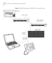
Guidelines for Network Configuration 17 Figure 5 Sample Network Topology with a 3Com Wireless Access Point Servers Switch or Hub 3Com Wireless Access Point Premises Cabling 3Com Ethernet Power Source Wiring Closet Patch Panel Laptop with Wireless PCM Card
Guidelines for Network Configuration 17 Figure 5 Sample Network Topology with a 3Com Wireless Access Point Servers Switch or Hub 3Com Wireless Access Point Premises Cabling 3Com Ethernet Power Source Wiring Closet Patch Panel Laptop with Wireless PCM Card
User Guide
Page 22
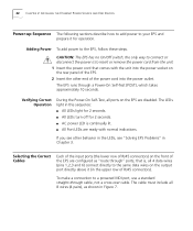
...pairs), as "route through" ports; the only way to connect or disconnect the power is continually lit. CAUTION: The EPS has no On/Off switch; If you see other end of the power cord into the power socket on the output port directly above it for operation. I All Port LEDs ... light for 2 seconds. The LEDs light in this sequence: I All LEDs turn off for 2 seconds. 22 CHAPTER 2: INSTALLING THE ETHERNET POWER SOURCE AND END DEVICES Power-up Sequence The following sections describe how to add power to your EPS and prepare it (in the upper row of RJ45 connectors). Adding...
...pairs), as "route through" ports; the only way to connect or disconnect the power is continually lit. CAUTION: The EPS has no On/Off switch; If you see other end of the power cord into the power socket on the output port directly above it for operation. I All Port LEDs ... light for 2 seconds. The LEDs light in this sequence: I All LEDs turn off for 2 seconds. 22 CHAPTER 2: INSTALLING THE ETHERNET POWER SOURCE AND END DEVICES Power-up Sequence The following sections describe how to add power to your EPS and prepare it (in the upper row of RJ45 connectors). Adding...

User Guide
Page 23
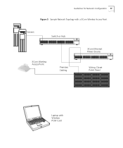
Rx Data Signal from DTE 2 P_RX - Selecting the Correct Cables 23 Figure 7 Connecting Other Devices to the Power Source Unit o e ub Switch/Hub RJ-IN RJ-OUT DTE/Splitter RJ45 RJ45 1 2 3 4 5 6 7 8 data data data spare spare data spare spare 1 2 3 4 5 6 7 8 1 2 3 data data data 1 2 3 4 5 6 DC...Data Signal to DTE 4 -24Vdc_return (+) Feeding power (+) 5 -24Vdc_return (+) Feeding power (+) 6 P_TX - RX + Spare Spare RX - Tx Data Signal to switch or hub Rx data signal from switch or hub Unused Unused Rx data signal from switch or hub Unused Unused Connector shielding Table 5...
Rx Data Signal from DTE 2 P_RX - Selecting the Correct Cables 23 Figure 7 Connecting Other Devices to the Power Source Unit o e ub Switch/Hub RJ-IN RJ-OUT DTE/Splitter RJ45 RJ45 1 2 3 4 5 6 7 8 data data data spare spare data spare spare 1 2 3 4 5 6 7 8 1 2 3 data data data 1 2 3 4 5 6 DC...Data Signal to DTE 4 -24Vdc_return (+) Feeding power (+) 5 -24Vdc_return (+) Feeding power (+) 6 P_TX - RX + Spare Spare RX - Tx Data Signal to switch or hub Rx data signal from switch or hub Unused Unused Rx data signal from switch or hub Unused Unused Connector shielding Table 5...

User Guide
Page 31
If none of these procedures identifies the problem, contact an authorized 3Com service representative for additional assistance. If operating properly. The NBX NCP is not I If the date and time appear in the LCD display... properly, the NCP is functioning properly. Verify all connections between the telephone and the NCP (patch cables, premises wiring, hubs, and switches). If operating properly. Telephone receives power, date and time appear in the LCD display. I Check other telephones. Solving NBX Telephone Problems 31 Table 7 Solving NBX Business Telephone...
If none of these procedures identifies the problem, contact an authorized 3Com service representative for additional assistance. If operating properly. The NBX NCP is not I If the date and time appear in the LCD display... properly, the NCP is functioning properly. Verify all connections between the telephone and the NCP (patch cables, premises wiring, hubs, and switches). If operating properly. Telephone receives power, date and time appear in the LCD display. I Check other telephones. Solving NBX Telephone Problems 31 Table 7 Solving NBX Business Telephone...

User Guide
Page 33
... these procedures identifies the problem, contact an authorized 3Com service representative for additional assistance. Check patch panels, premises wiring, hubs, and switches. Solving Wireless Access Point Problems 33 Table 8 ...Solving Wireless Access Point Problems (continued) Problem Possible Cause Suggested Action Faulty EPS I Check all physical connections between the Wireless Access Point and the LAN (network). I Follow the procedures described in Table 6 to determine if the EPS is Faulty network receiving power...
... these procedures identifies the problem, contact an authorized 3Com service representative for additional assistance. Check patch panels, premises wiring, hubs, and switches. Solving Wireless Access Point Problems 33 Table 8 ...Solving Wireless Access Point Problems (continued) Problem Possible Cause Suggested Action Faulty EPS I Check all physical connections between the Wireless Access Point and the LAN (network). I Follow the procedures described in Table 6 to determine if the EPS is Faulty network receiving power...

User Guide
Page 42
Table 12 Pin Assignments Pin Number Signal Input Ports (Data + Power) 1 RxData + 2 RxData - 3 TxData + 4 - 24vDC + 5 - 24vDC + 6 TxData - 7 - 24vDC (-) 8 - 24vDC (-) Input Ports (Data only) 1 TxData + 2 TxData - 3 RxData + 4 Not assigned 5 Not assigned...feeding Transmit data to DTE / NIC Return signal feeding Return signal feeding Transmit data to switch Transmit data to switch Receive data from switch Terminated Terminated Receive data from switch Terminated Terminated 42 APPENDIX B: TECHNICAL SPECIFICATIONS AND PIN ASSIGNMENTS Pin assignments are the same for...
Table 12 Pin Assignments Pin Number Signal Input Ports (Data + Power) 1 RxData + 2 RxData - 3 TxData + 4 - 24vDC + 5 - 24vDC + 6 TxData - 7 - 24vDC (-) 8 - 24vDC (-) Input Ports (Data only) 1 TxData + 2 TxData - 3 RxData + 4 Not assigned 5 Not assigned...feeding Transmit data to DTE / NIC Return signal feeding Return signal feeding Transmit data to switch Transmit data to switch Receive data from switch Terminated Terminated Receive data from switch Terminated Terminated 42 APPENDIX B: TECHNICAL SPECIFICATIONS AND PIN ASSIGNMENTS Pin assignments are the same for...