User Guide
Page 3
... 2000 Compliance 6 3Com Support 7 1 3COM ETHERNET POWER SOURCE OVERVIEW Overview 10 Features 10 Front Panel Connections and LEDs 11 10/100BASE-TX Data Input Ports 11 10/100BASE-TX Data and Power Output Ports 12 LEDs 12 Rear Panel Connections 14 Information Label 14 Console Port 14 DC Power Socket 15 AC Power Socket 15 Guidelines for Network Configuration 15 2 INSTALLING THE ETHERNET POWER SOURCE AND END DEVICES...
... 2000 Compliance 6 3Com Support 7 1 3COM ETHERNET POWER SOURCE OVERVIEW Overview 10 Features 10 Front Panel Connections and LEDs 11 10/100BASE-TX Data Input Ports 11 10/100BASE-TX Data and Power Output Ports 12 LEDs 12 Rear Panel Connections 14 Information Label 14 Console Port 14 DC Power Socket 15 AC Power Socket 15 Guidelines for Network Configuration 15 2 INSTALLING THE ETHERNET POWER SOURCE AND END DEVICES...
User Guide
Page 5
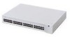
...-T/100BASE-TX ports The guide is intended for installing and setting up network equipment. Table 1 and Table 2 list conventions that are responsible for use either of the Ethernet Power Source (EPS) units: I 3C10222 - with 12 10BASE-T/100BASE-TX ports I 3C10220 - Table 1 Notice Icons Icon Notice Type Description Information note Information that describes important features or instructions Caution Information that alerts...
...-T/100BASE-TX ports The guide is intended for installing and setting up network equipment. Table 1 and Table 2 list conventions that are responsible for use either of the Ethernet Power Source (EPS) units: I 3C10222 - with 12 10BASE-T/100BASE-TX ports I 3C10220 - Table 1 Notice Icons Icon Notice Type Description Information note Information that describes important features or instructions Caution Information that alerts...
User Guide
Page 9
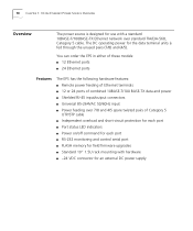
1 3COM ETHERNET POWER SOURCE OVERVIEW The 3Com Ethernet Power Source (EPS) provides power, over the Ethernet cable, and supply power only to those devices capable of the Ethernet Power Source I Front Panel Connections and LEDs I Rear Panel Connections I Guidelines for AC outlets, Uninterrupted Power Supplies (UPS), and AC/DC adapters I Allows you to devices such as NBX telephones and 3Com wireless access points. The EPS: I Eliminates the need for Network Configuration I Is easy...
1 3COM ETHERNET POWER SOURCE OVERVIEW The 3Com Ethernet Power Source (EPS) provides power, over the Ethernet cable, and supply power only to those devices capable of the Ethernet Power Source I Front Panel Connections and LEDs I Rear Panel Connections I Guidelines for AC outlets, Uninterrupted Power Supplies (UPS), and AC/DC adapters I Allows you to devices such as NBX telephones and 3Com wireless access points. The EPS: I Eliminates the need for Network Configuration I Is easy...
User Guide
Page 10
10 CHAPTER 1: 3COM ETHERNET POWER SOURCE OVERVIEW Overview The power source is designed for the data terminal units is fed through the unused pairs (7/8) and (4/5). The DC operating power for use with hardware I Standard 19" 1.5U rack mounting with a standard 10BASE-T/100BASE-TX Ethernet network over 7/8 and 4/5 spare twisted pairs of combined 10BASE-T/100 BASE-TX data and power I Shielded RJ-45 input/output connectors I Universal...
10 CHAPTER 1: 3COM ETHERNET POWER SOURCE OVERVIEW Overview The power source is designed for the data terminal units is fed through the unused pairs (7/8) and (4/5). The DC operating power for use with hardware I Standard 19" 1.5U rack mounting with a standard 10BASE-T/100BASE-TX Ethernet network over 7/8 and 4/5 spare twisted pairs of combined 10BASE-T/100 BASE-TX data and power I Shielded RJ-45 input/output connectors I Universal...
User Guide
Page 11
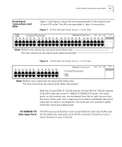
.... Front View Note: Bottom row connectors are output ports (data and power). Figure 2 12-Port Ethernet Power Source - Both the 12-port (P/N 3C10220) and the 24-port (P/N 3C10222) versions of the EPS have two rows of the 24-port and 12-port EPS units. You must use non crossover cables with both input and output ports. 10/100BASE-TX The EPS...
.... Front View Note: Bottom row connectors are output ports (data and power). Figure 2 12-Port Ethernet Power Source - Both the 12-port (P/N 3C10220) and the 24-port (P/N 3C10222) versions of the EPS have two rows of the 24-port and 12-port EPS units. You must use non crossover cables with both input and output ports. 10/100BASE-TX The EPS...
User Guide
Page 12
... EPS Problems" in Chapter 3. Port power is plugged into the port. The EPS has shut off the port power. or I An internal fault has occurred on pins 1 and 2; 12 CHAPTER 1: 3COM ETHERNET POWER SOURCE OVERVIEW 10/100BASE-TX Data and Power Output Ports The EPS output ports (top row) carry two kinds of transmissions: I Normal condition. Off On I Ethernet data on the standard two wire pairs...
... EPS Problems" in Chapter 3. Port power is plugged into the port. The EPS has shut off the port power. or I An internal fault has occurred on pins 1 and 2; 12 CHAPTER 1: 3COM ETHERNET POWER SOURCE OVERVIEW 10/100BASE-TX Data and Power Output Ports The EPS output ports (top row) carry two kinds of transmissions: I Normal condition. Off On I Ethernet data on the standard two wire pairs...
User Guide
Page 14
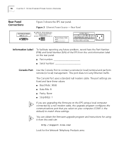
... Port Use the Console Port to match these settings. You can obtain the firmware upgrade program and instructions for the Network Telephony Products area. REFER TO INSTRUCTIONS MANUAL. Power Source Unit P/N S/N SUPPLY DATA V~ Hz A 100-120/200-240 60/50 3/1.5 Caution: Shock Potential. Rear Panel DC INPUTS: 24Vdc/16Amp max. This port does not carry Ethernet traffic. 14 CHAPTER 1: 3COM ETHERNET POWER SOURCE OVERVIEW Rear Panel Connections...
... Port Use the Console Port to match these settings. You can obtain the firmware upgrade program and instructions for the Network Telephony Products area. REFER TO INSTRUCTIONS MANUAL. Power Source Unit P/N S/N SUPPLY DATA V~ Hz A 100-120/200-240 60/50 3/1.5 Caution: Shock Potential. Rear Panel DC INPUTS: 24Vdc/16Amp max. This port does not carry Ethernet traffic. 14 CHAPTER 1: 3COM ETHERNET POWER SOURCE OVERVIEW Rear Panel Connections...

User Guide
Page 15
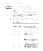
... DC Power Socket The EPS has a 12-pin DC power socket for Network Configuration Design your UPS. Sample topologies are shown in the EPS draws power from the main switch or hub to the EPS output ports. If an external DC supply is 100 m (328 ft.) using Category 5 cable (from either the internal or external supply to ensure steady power delivery...
... DC Power Socket The EPS has a 12-pin DC power socket for Network Configuration Design your UPS. Sample topologies are shown in the EPS draws power from the main switch or hub to the EPS output ports. If an external DC supply is 100 m (328 ft.) using Category 5 cable (from either the internal or external supply to ensure steady power delivery...
User Guide
Page 19
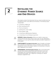
... ETHERNET POWER SOURCE AND END DEVICES This chapter contains the information that you must read the safety information provided in diesem Handbuch aufgefuehrt sind. Before you install or remove any components from the Power Source unit or carry out any maintenance procedures, you need to install and set up Sequence I Selecting the Correct Cables I Power Splitter Cable I Connecting an NBX Business Telephone I Connecting a 3Com...
... ETHERNET POWER SOURCE AND END DEVICES This chapter contains the information that you must read the safety information provided in diesem Handbuch aufgefuehrt sind. Before you install or remove any components from the Power Source unit or carry out any maintenance procedures, you need to install and set up Sequence I Selecting the Correct Cables I Power Splitter Cable I Connecting an NBX Business Telephone I Connecting a 3Com...
User Guide
Page 20
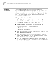
...Ethernet, including the 100-meter limit on all sides of the EPS for proper cooling. 3Com recommends that you provide a minimum of 25 mm (1 in a single stack. If you use . I Locate the EPS so that no water or moisture can connect cables easily. I If you mount multiple EPS units in a wiring... table, or counter. Both the 12-port and 24-port EPS packages (3C10220 and 3C10222 respectively) contain a rack-mounting kit with two mounting brackets and six screws. 20 CHAPTER 2: INSTALLING THE ETHERNET POWER SOURCE AND END DEVICES Choosing a Suitable Site The EPS is not designed for an...
...Ethernet, including the 100-meter limit on all sides of the EPS for proper cooling. 3Com recommends that you provide a minimum of 25 mm (1 in a single stack. If you use . I Locate the EPS so that no water or moisture can connect cables easily. I If you mount multiple EPS units in a wiring... table, or counter. Both the 12-port and 24-port EPS packages (3C10220 and 3C10222 respectively) contain a rack-mounting kit with two mounting brackets and six screws. 20 CHAPTER 2: INSTALLING THE ETHERNET POWER SOURCE AND END DEVICES Choosing a Suitable Site The EPS is not designed for an...
User Guide
Page 22
... RJ45 connectors) on the output port directly above it for 2 seconds. The EPS runs through " ports; The cable must include all 4 data wires (pins 1,2,3 and 6) connect directly to the same data wires on the front of RJ45 connectors). CAUTION: The EPS has no On/Off switch; the only way to connect or disconnect the power is , all 8 wires (4 pairs), as "route through a Power-On Self-Test...
... RJ45 connectors) on the output port directly above it for 2 seconds. The EPS runs through " ports; The cable must include all 4 data wires (pins 1,2,3 and 6) connect directly to the same data wires on the front of RJ45 connectors). CAUTION: The EPS has no On/Off switch; the only way to connect or disconnect the power is , all 8 wires (4 pairs), as "route through a Power-On Self-Test...

User Guide
Page 24
... Business Telephone Ethernet Power Source NBX Telephone Wiring Closet Patch Panel Wall Jack Premises Cabling Splitter The RJ45 carries the data signals (transmit and receive) on this connector are connected, either to the power or to data. This connection may involve multiple segments such as the patch panel and premises cabling shown in Chapter 1 for continuity on all eight wires, connect an EPS output port...
... Business Telephone Ethernet Power Source NBX Telephone Wiring Closet Patch Panel Wall Jack Premises Cabling Splitter The RJ45 carries the data signals (transmit and receive) on this connector are connected, either to the power or to data. This connection may involve multiple segments such as the patch panel and premises cabling shown in Chapter 1 for continuity on all eight wires, connect an EPS output port...
User Guide
Page 25
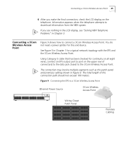
... of connectors) to the data jack closest to a 3Com Wireless Access Point Ethernet Power Source 3Com Wireless Access Point Wiring Closet Patch Panel Premises Cabling Connecting a 3Com Wireless Access Point 25 4 After you see nothing in the LCD display, see "Solving NBX Telephone Problems" in Chapter 3. See Figure 5 in Figure 9. Using Category 5 cable that has been checked for continuity on all eight wires, connect an EPS output...
... of connectors) to the data jack closest to a 3Com Wireless Access Point Ethernet Power Source 3Com Wireless Access Point Wiring Closet Patch Panel Premises Cabling Connecting a 3Com Wireless Access Point 25 4 After you see nothing in the LCD display, see "Solving NBX Telephone Problems" in Chapter 3. See Figure 5 in Figure 9. Using Category 5 cable that has been checked for continuity on all eight wires, connect an EPS output...

User Guide
Page 26
If the Wireless Access Point LEDs do not light, refer to flash until the Wireless Access Point completes the bootstrap sequence. 26 CHAPTER 2: INSTALLING THE ETHERNET POWER SOURCE AND END DEVICES When the connection is a connection to the Ethernet, the Ethernet status LED flashes. I The power LED continues to "Solving Wireless Access Point Problems" in Chapter 3. If there is complete between the EPS and the 3Com Wireless Access Point, verify that: I The Power LED then stays illuminated.
If the Wireless Access Point LEDs do not light, refer to flash until the Wireless Access Point completes the bootstrap sequence. 26 CHAPTER 2: INSTALLING THE ETHERNET POWER SOURCE AND END DEVICES When the connection is a connection to the Ethernet, the Ethernet status LED flashes. I The power LED continues to "Solving Wireless Access Point Problems" in Chapter 3. If there is complete between the EPS and the 3Com Wireless Access Point, verify that: I The Power LED then stays illuminated.

User Guide
Page 27
... the AC outlet, but there is still no power available, check for some other end of the connections are secure and there is still no power to the supply outlet. 3 TROUBLESHOOTING Solving EPS Problems If the LEDs on the EPS indicate a problem, see Table 6 for a building power problem such as a burned-out fuse or an open circuit breaker. Contact an...
... the AC outlet, but there is still no power available, check for some other end of the connections are secure and there is still no power to the supply outlet. 3 TROUBLESHOOTING Solving EPS Problems If the LEDs on the EPS indicate a problem, see Table 6 for a building power problem such as a burned-out fuse or an open circuit breaker. Contact an...

User Guide
Page 28
... connection I Check the device specification to determine whether these pins are no harm to either the device or the EPS. the port does not light. Faulty Ethernet cable I Some Ethernet devices (for example, accept power via the Ethernet cable. If these pins are not twisted, corrupted, or shorted together. The device is receiving connected device power. 28 CHAPTER 3: TROUBLESHOOTING Table 6 Solving EPS Problems (continued) Problem...
... connection I Check the device specification to determine whether these pins are no harm to either the device or the EPS. the port does not light. Faulty Ethernet cable I Some Ethernet devices (for example, accept power via the Ethernet cable. If these pins are not twisted, corrupted, or shorted together. The device is receiving connected device power. 28 CHAPTER 3: TROUBLESHOOTING Table 6 Solving EPS Problems (continued) Problem...

User Guide
Page 30
... that is wired for all physical connections. The telephone may I Replace the power splitter. Faulty power splitter I Supply power to an EPS output port (one that is not the source of connectors). telephone using the standard external adapter that the Ethernet wall jack is connected to use the information in the LCD display, replace the Ethernet patch cable, being sure to the EPS. I Verify all eight pins. Faulty connection between...
... that is wired for all physical connections. The telephone may I Replace the power splitter. Faulty power splitter I Supply power to an EPS output port (one that is not the source of connectors). telephone using the standard external adapter that the Ethernet wall jack is connected to use the information in the LCD display, replace the Ethernet patch cable, being sure to the EPS. I Verify all eight pins. Faulty connection between...

User Guide
Page 36
... EPS to an earth (ground) connection when you connect it is the connector to the unit, not to IEC 950. and Canada Denmark Switzerland I The cord set must always be near to an AC outlet (power supply). I The power cord set must be carried out by disconnecting the power cord from the outlet. I The attachment plug must be approved for mating with a NEMA...
... EPS to an earth (ground) connection when you connect it is the connector to the unit, not to IEC 950. and Canada Denmark Switzerland I The cord set must always be near to an AC outlet (power supply). I The power cord set must be carried out by disconnecting the power cord from the outlet. I The attachment plug must be approved for mating with a NEMA...

User Guide
Page 41
B TECHNICAL SPECIFICATIONS AND PIN ASSIGNMENTS Table 11 Technical Specifications for 100BASE-TX ports) complies with the Class B requirements of unscreened cables (category 3 or 5 for 10BASE-T ports or category 5 for the Ethernet Power Source Physical Dimensions Environmental Requirements Operating Temperature Storage Temperature Operating Humidity Standards Safety Agency Certifications EMC Emissions Immunity Heat Dissipation Power Supply AC Line Frequency Input Voltage Options Current...
B TECHNICAL SPECIFICATIONS AND PIN ASSIGNMENTS Table 11 Technical Specifications for 100BASE-TX ports) complies with the Class B requirements of unscreened cables (category 3 or 5 for 10BASE-T ports or category 5 for the Ethernet Power Source Physical Dimensions Environmental Requirements Operating Temperature Storage Temperature Operating Humidity Standards Safety Agency Certifications EMC Emissions Immunity Heat Dissipation Power Supply AC Line Frequency Input Voltage Options Current...
User Guide
Page 43
... or specifications as not meeting this standard. 3Com Corporation LIMITED WARRANTY 3COM ETHERNET POWER SOURCE 12-PORT UNIT (3C10220) AND 24-PORT UNIT (3C10222) HARDWARE 3Com warrants this hardware product to be free from defects in workmanship and materials, under normal use of the software product not in accordance with 3Com's published specifications or user manual. In the event a product completely fails to obtain warranty service authorization...
... or specifications as not meeting this standard. 3Com Corporation LIMITED WARRANTY 3COM ETHERNET POWER SOURCE 12-PORT UNIT (3C10220) AND 24-PORT UNIT (3C10222) HARDWARE 3Com warrants this hardware product to be free from defects in workmanship and materials, under normal use of the software product not in accordance with 3Com's published specifications or user manual. In the event a product completely fails to obtain warranty service authorization...
