
Owners Manual
Page 6
... WARNING AND SPECIFICATION LABELS...1-1 SAFETY INFORMATION...2-1 DESCRIPTION AND MACHINE IDENTIFICATION ...3-1 Identification number records...3-2 Key identification number...3-2 Vehicle identification number ...3-3 Model label ...3-3 2 3 CONTROL FUNCTIONS...4-1 Main switch ...4-1 Indicator and warning lights ...4-2 Handlebar switches ...4-5 Throttle lever ...4-8 Speed limiter ...4-9 Front brake lever...4-10 Brake pedal and rear brake lever ...4-10 Parking brake...4-11 Drive select lever ...4-12 Recoil starter...4-12 Fuel tank cap ...4-13 Fuel cock...4-14 Starter (choke) ...4-15 Seat...4-16...
... WARNING AND SPECIFICATION LABELS...1-1 SAFETY INFORMATION...2-1 DESCRIPTION AND MACHINE IDENTIFICATION ...3-1 Identification number records...3-2 Key identification number...3-2 Vehicle identification number ...3-3 Model label ...3-3 2 3 CONTROL FUNCTIONS...4-1 Main switch ...4-1 Indicator and warning lights ...4-2 Handlebar switches ...4-5 Throttle lever ...4-8 Speed limiter ...4-9 Front brake lever...4-10 Brake pedal and rear brake lever ...4-10 Parking brake...4-11 Drive select lever ...4-12 Recoil starter...4-12 Fuel tank cap ...4-13 Fuel cock...4-14 Starter (choke) ...4-15 Seat...4-16...
Owners Manual
Page 7
5 PRE-OPERATION CHECKS ...5-1 Front and rear brakes ...5-2 Fuel ...5-4 Engine oil ...5-6 Final gear oil...5-6 Differential gear oil ...5-7 Throttle lever ...5-7 Fittings and fasteners...5-7 Lights...5-7 Switches...5-7 Tires ...5-8 How to measure tire pressure...5-10 Tire wear limit...5-11 OPERATION...6-1 Starting a cold engine ...6-1 Starting a warm engine...6-3 Warming up...6-3 Drive select lever operation and reverse driving...6-4 Engine break-in...6-7 Parking ...6-8 Parking on a slope ...6-9 Accessories and loading ...6-10 7 RIDING YOUR ATV ...7-1 Getting to know your ATV ...7-3 Ride with...
5 PRE-OPERATION CHECKS ...5-1 Front and rear brakes ...5-2 Fuel ...5-4 Engine oil ...5-6 Final gear oil...5-6 Differential gear oil ...5-7 Throttle lever ...5-7 Fittings and fasteners...5-7 Lights...5-7 Switches...5-7 Tires ...5-8 How to measure tire pressure...5-10 Tire wear limit...5-11 OPERATION...6-1 Starting a cold engine ...6-1 Starting a warm engine...6-3 Warming up...6-3 Drive select lever operation and reverse driving...6-4 Engine break-in...6-7 Parking ...6-8 Parking on a slope ...6-9 Accessories and loading ...6-10 7 RIDING YOUR ATV ...7-1 Getting to know your ATV ...7-3 Ride with...
Owners Manual
Page 8
... ...8-4 Panel removal and installation ...8-6 Engine oil and oil filter cartridge ...8-7 Final gear oil ...8-12 Differential gear oil replacement ...8-15 Axle boots...8-17 Spark plug inspection...8-17 Air filter element cleaning...8-20 V-belt cooling duct check hose ...8-23 V-belt case drain plug...8-23 Spark arrester cleaning ...8-24 Carburetor adjustment...8-25 Idle speed adjustment ...8-26 Valve clearance adjustment ...8-26 Select lever safety system cable adjustment...8-27 Throttle lever adjustment...8-27 Front brake pad check ...8-28 Rear brake shoe inspection...8-29 Brake fluid level...
... ...8-4 Panel removal and installation ...8-6 Engine oil and oil filter cartridge ...8-7 Final gear oil ...8-12 Differential gear oil replacement ...8-15 Axle boots...8-17 Spark plug inspection...8-17 Air filter element cleaning...8-20 V-belt cooling duct check hose ...8-23 V-belt case drain plug...8-23 Spark arrester cleaning ...8-24 Carburetor adjustment...8-25 Idle speed adjustment ...8-26 Valve clearance adjustment ...8-26 Select lever safety system cable adjustment...8-27 Throttle lever adjustment...8-27 Front brake pad check ...8-28 Rear brake shoe inspection...8-29 Brake fluid level...
Owners Manual
Page 20
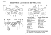
Rear shock absorber assembly spring preload adjusting ring 2. Spark plug 5. Fuel cock 9. Left handlebar switches 17. Drive select lever 19. Main switch 20. Fuses 11. Starter (choke) 18. V-belt case 8. Air filter case 10. Engine oil dipstick 15. Fuel tank cap 21. Rear brake lever 16. On-Command four-wheel drive switch 22. Throttle lever 23. Storage box and tool kit 4. Front shock absorber assembly spring preload adjusting ring 6. EBU00032 1- DESCRIPTION AND MACHINE IDENTIFICATION 1. Brake pedal 7. Front brake lever NOTE: The machine you...
Rear shock absorber assembly spring preload adjusting ring 2. Spark plug 5. Fuel cock 9. Left handlebar switches 17. Drive select lever 19. Main switch 20. Fuses 11. Starter (choke) 18. V-belt case 8. Air filter case 10. Engine oil dipstick 15. Fuel tank cap 21. Rear brake lever 16. On-Command four-wheel drive switch 22. Throttle lever 23. Storage box and tool kit 4. Front shock absorber assembly spring preload adjusting ring 6. EBU00032 1- DESCRIPTION AND MACHINE IDENTIFICATION 1. Brake pedal 7. Front brake lever NOTE: The machine you...
Owners Manual
Page 25
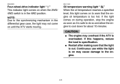
... the engine. _ 4-3 EBU00605 EBU11400 Four-wheel-drive indicator light " " This indicator light comes on when the 2WD/ 4WD switch is in the differential gear case, the light may not come on until the ATV starts moving. If this light comes on to the synchronizing mechanism in the 4WD position. If the light comes on may overheat if the ATV is out. NOTE: Due to warn...
... the engine. _ 4-3 EBU00605 EBU11400 Four-wheel-drive indicator light " " This indicator light comes on when the 2WD/ 4WD switch is in the differential gear case, the light may not come on until the ATV starts moving. If this light comes on to the synchronizing mechanism in the 4WD position. If the light comes on may overheat if the ATV is out. NOTE: Due to warn...
Owners Manual
Page 27
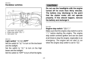
... to turn on the low beam and the taillight. The engine will not operate properly. EBU00053 Handlebar switches _ CAUTION: Do not use the headlights with the engine turned off all times to " ". The engine stop switch controls ignition and can be used at all the lights. 4-5 Engine stop switch " / " Make sure that the starter motor will not start or run when the engine stop switch is set to stop switch " / " 3. Light switch " / /OFF...
... to turn on the low beam and the taillight. The engine will not operate properly. EBU00053 Handlebar switches _ CAUTION: Do not use the headlights with the engine turned off all times to " ". The engine stop switch controls ignition and can be used at all the lights. 4-5 Engine stop switch " / " Make sure that the starter motor will not start or run when the engine stop switch is set to stop switch " / " 3. Light switch " / /OFF...
Owners Manual
Page 30
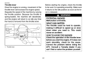
EBU00062 Throttle lever Once the engine is running, movement of throttle. WHAT CAN HAPPEN The throttle could cause an accident. Consult a Yamaha dealer if you start the engine. WARNING POTENTIAL HAZARD Malfunction of the throttle lever will return to the idle position as soon as the lever is removed from the throttle lever. If it returns to an idle any time the hand is released. Throttle lever...
EBU00062 Throttle lever Once the engine is running, movement of throttle. WHAT CAN HAPPEN The throttle could cause an accident. Consult a Yamaha dealer if you start the engine. WARNING POTENTIAL HAZARD Malfunction of the throttle lever will return to the idle position as soon as the lever is removed from the throttle lever. If it returns to an idle any time the hand is released. Throttle lever...
Owners Manual
Page 45
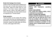
If a problem cannot be a leak in this manual, have a Yamaha dealer check for the cause. 5-3 If there is leaking out of the hose, joint or brake fluid reservoir of every ride. HOW TO AVOID THE HAZARD Always check the brakes at slow speed after starting out to make sure they are working properly. Apply the brake firmly for wear. (See pages 8-28-8-29.) WARNING POTENTIAL HAZARD...
If a problem cannot be a leak in this manual, have a Yamaha dealer check for the cause. 5-3 If there is leaking out of the hose, joint or brake fluid reservoir of every ride. HOW TO AVOID THE HAZARD Always check the brakes at slow speed after starting out to make sure they are working properly. Apply the brake firmly for wear. (See pages 8-28-8-29.) WARNING POTENTIAL HAZARD...
Owners Manual
Page 54
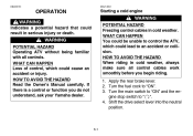
... the Owner's Manual carefully. If there is a control or function you begin riding. 1. Turn the main switch to "ON" and the engine stop switch to "ON". 3. Shift the drive select lever into the neutral position. WARNING POTENTIAL HAZARD Operating ATV without being familiar with all control cables work smoothly before you do not understand, ask your Yamaha dealer. 6-1 Turn the fuel cock to " ". 4. Apply the rear brake...
... the Owner's Manual carefully. If there is a control or function you begin riding. 1. Turn the main switch to "ON" and the engine stop switch to "ON". 3. Shift the drive select lever into the neutral position. WARNING POTENTIAL HAZARD Operating ATV without being familiar with all control cables work smoothly before you do not understand, ask your Yamaha dealer. 6-1 Turn the fuel cock to " ". 4. Apply the rear brake...
Owners Manual
Page 55
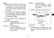
... the throttle lever and start the engine by pushing the start position. 1 2 3 4 5 6 7 8 9 10 5. If it is recommended to shift into neutral before starting the engine. _ _ Position 3: Cold engine startambient temperature above 25 °C (80 °F) and warm engine start switch. 6-2 Starter (choke) 2. Use the starter (choke) in any gear if the rear brake lever is applied. a. Half open 3. G The engine can be started in reference to the figure: Position 1: Cold engine...
... the throttle lever and start the engine by pushing the start position. 1 2 3 4 5 6 7 8 9 10 5. If it is recommended to shift into neutral before starting the engine. _ _ Position 3: Cold engine startambient temperature above 25 °C (80 °F) and warm engine start switch. 6-2 Starter (choke) 2. Use the starter (choke) in any gear if the rear brake lever is applied. a. Half open 3. G The engine can be started in reference to the figure: Position 1: Cold engine...
Owners Manual
Page 86
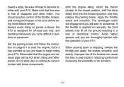
... front wheels may lift off the ground resulting in contact with these components. Always avoid riding on paved surfaces: the ATV is free of obstacles and other riders. Avoid higher speeds until you are ready to the closed position, shift the drive select lever into the forward position, and then release the parking brake. With the engine idling, return the starter (choke...
... front wheels may lift off the ground resulting in contact with these components. Always avoid riding on paved surfaces: the ATV is free of obstacles and other riders. Avoid higher speeds until you are ready to the closed position, shift the drive select lever into the forward position, and then release the parking brake. With the engine idling, return the starter (choke...

Owners Manual
Page 107
... 1- Safety is running. The most efficient condition possible. The tools provided in the Owner's tool kit are recommended to properly tighten nuts and bolts. Put the owner's tool kit and low-pressure tire gauge under the seat. PERIODIC MAINTENANCE AND ADJUSTMENT Periodic inspection, adjustment and lubrication will keep your own preventive maintenance and minor repairs. EBU14510 WARNING POTENTIAL HAZARD Servicing an engine while it on the following pages. Electrical...
... 1- Safety is running. The most efficient condition possible. The tools provided in the Owner's tool kit are recommended to properly tighten nuts and bolts. Put the owner's tool kit and low-pressure tire gauge under the seat. PERIODIC MAINTENANCE AND ADJUSTMENT Periodic inspection, adjustment and lubrication will keep your own preventive maintenance and minor repairs. EBU14510 WARNING POTENTIAL HAZARD Servicing an engine while it on the following pages. Electrical...
Owners Manual
Page 109
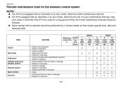
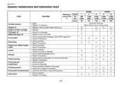
...) (3,200) 160 320 Valves* Spark plug Carburetor* Cylinder head cover breather system* Exhaust system* Spark arrester Fuel line* Check valve clearance. Check and adjust idle speed/starter operation. Adjust if necessary. Replace if necessary. Check for the emission control system NOTE: _ G For ATVs not equipped with an odometer or an hour meter, follow the km (mi) or hours maintenance intervals. Check fuel hose for cracks or damage...
...) (3,200) 160 320 Valves* Spark plug Carburetor* Cylinder head cover breather system* Exhaust system* Spark arrester Fuel line* Check valve clearance. Check and adjust idle speed/starter operation. Adjust if necessary. Replace if necessary. Check for the emission control system NOTE: _ G For ATVs not equipped with an odometer or an hour meter, follow the km (mi) or hours maintenance intervals. Check fuel hose for cracks or damage...
Owners Manual
Page 110
... operation. Replace if necessary. Adjust if necessary. Check for cracks or damage. Check balance/damage/runout. Check toe-in wet or dusty areas.) ITEM ROUTINE Air filter element Engine oil Engine oil filter cartridge Final gear oil Differential gear oil Front brake* Rear brake Select lever safety system cable* V-belt* Wheels* Wheel bearing* Front and rear suspension* Steering system* Drive shaft universal joint* Axle boots* Clean. Correct if necessary. Check operation. Repair if necessary. Replace if damaged. Replace if damaged...
... operation. Replace if necessary. Adjust if necessary. Check for cracks or damage. Check balance/damage/runout. Check toe-in wet or dusty areas.) ITEM ROUTINE Air filter element Engine oil Engine oil filter cartridge Final gear oil Differential gear oil Front brake* Rear brake Select lever safety system cable* V-belt* Wheels* Wheel bearing* Front and rear suspension* Steering system* Drive shaft universal joint* Axle boots* Clean. Correct if necessary. Check operation. Repair if necessary. Replace if damaged. Replace if damaged...
Owners Manual
Page 141
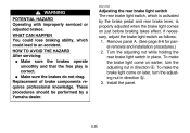
... direction b. 3. Adjusting the rear brake light switch The rear brake light switch, which could lead to an accident. Turn the adjusting nut while holding the rear brake light switch in direction a. Replacement of brake components requires professional knowledge. Install the panel. 8-35 EBU12590 WARNING POTENTIAL HAZARD Operating with improperly serviced or adjusted brakes. To make the brake light come on just before braking takes effect. Remove panel A. (See page 8-6 for panel removal and installation...
... direction b. 3. Adjusting the rear brake light switch The rear brake light switch, which could lead to an accident. Turn the adjusting nut while holding the rear brake light switch in direction a. Replacement of brake components requires professional knowledge. Install the panel. 8-35 EBU12590 WARNING POTENTIAL HAZARD Operating with improperly serviced or adjusted brakes. To make the brake light come on just before braking takes effect. Remove panel A. (See page 8-6 for panel removal and installation...
Owners Manual
Page 142
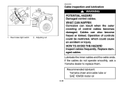
... cables frequently. Rear brake light switch 2. Recommended lubricant: Yamaha chain and cable lube or SAE 10W30 motor oil 8-36 1. WHAT CAN HAPPEN Corrosion can also become frayed or kinked. Cables can result when the outer covering of controls could be restricted, which could cause an accident or injury. EBU00356 Cable inspection and lubrication WARNING POTENTIAL HAZARD Damaged control cables. Replace damaged cables. Lubricate...
... cables frequently. Rear brake light switch 2. Recommended lubricant: Yamaha chain and cable lube or SAE 10W30 motor oil 8-36 1. WHAT CAN HAPPEN Corrosion can also become frayed or kinked. Cables can result when the outer covering of controls could be restricted, which could cause an accident or injury. EBU00356 Cable inspection and lubrication WARNING POTENTIAL HAZARD Damaged control cables. Replace damaged cables. Lubricate...
Owners Manual
Page 148
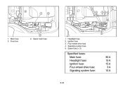
Fuse box 2. Spare main fuse 1. 2. 3. 4. 5. Headlight fuse Ignition fuse Four-wheel drive fuse Signaling system fuse Spare fuse (× 3) Specified fuses: Main fuse: Headlight fuse: Ignition fuse: Four-wheel drive fuse: Signaling system fuse: 30 A 15 A 15 A 3A 10 A 8-42 1. Main fuse 3.
Fuse box 2. Spare main fuse 1. 2. 3. 4. 5. Headlight fuse Ignition fuse Four-wheel drive fuse Signaling system fuse Spare fuse (× 3) Specified fuses: Main fuse: Headlight fuse: Ignition fuse: Four-wheel drive fuse: Signaling system fuse: 30 A 15 A 15 A 3A 10 A 8-42 1. Main fuse 3.
Owners Manual
Page 156
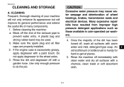
... appearance but will improve its general performance and extend the useful life of wheel bearings, brakes, transmission seals and electrical devices. Once the majority of the exhaust pipe to -get-at places. 5. Before cleaning the machine: a. Many expensive repair bills have resulted from improper high pressure detergent applications such as those available in coin-operated car washers. 4. Do not apply degreaser...
... appearance but will improve its general performance and extend the useful life of wheel bearings, brakes, transmission seals and electrical devices. Once the majority of the exhaust pipe to -get-at places. 5. Before cleaning the machine: a. Many expensive repair bills have resulted from improper high pressure detergent applications such as those available in coin-operated car washers. 4. Do not apply degreaser...
Owners Manual
Page 158
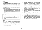
...: 1. Ground the spark plug wire and turn the engine over the exhaust pipe outlet to drain the fuel system. Block up the frame to guard against deterioration. STORAGE Long term storage (60 days or more) of Yamaha Fuel Stabilizer and Conditioner or an equivalent product. Lubricate all control cables. 4. Fill the fuel tank with oil. 3. Tie a plastic bag over several times to coat the cylinder wall with fresh fuel...
...: 1. Ground the spark plug wire and turn the engine over the exhaust pipe outlet to drain the fuel system. Block up the frame to guard against deterioration. STORAGE Long term storage (60 days or more) of Yamaha Fuel Stabilizer and Conditioner or an equivalent product. Lubricate all control cables. 4. Fill the fuel tank with oil. 3. Tie a plastic bag over several times to coat the cylinder wall with fresh fuel...
Owners Manual
Page 165
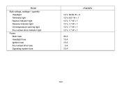
Model Bulb voltage, wattage × quantity: Headlight Tail/brake light Neutral indicator light Reverse indicator light Oil temperature warning light Four-wheel-drive indicator light Fuses: Main fuse Headlight fuse Ignition fuse Four-wheel drive fuse Signaling system fuse 12 V, 30/30 W × 2 12 V, 5/21 W × 1 12 V, 1.7 W × 1 12 V, 1.7 W × 1 12 V, 1.7 W × 1 12 V, 1.7 W × 1 30 A 15 A 15 A 3A 10 A YFM35FA 10-6
Model Bulb voltage, wattage × quantity: Headlight Tail/brake light Neutral indicator light Reverse indicator light Oil temperature warning light Four-wheel-drive indicator light Fuses: Main fuse Headlight fuse Ignition fuse Four-wheel drive fuse Signaling system fuse 12 V, 30/30 W × 2 12 V, 5/21 W × 1 12 V, 1.7 W × 1 12 V, 1.7 W × 1 12 V, 1.7 W × 1 12 V, 1.7 W × 1 30 A 15 A 15 A 3A 10 A YFM35FA 10-6