
Owners Manual
Page 6
... and panels ...6-8 Checking the spark plugs ...6-9 Engine oil and oil filter cartridge ...6-10 Final gear oil ...6-13 Coolant ...6-14 Cleaning the air filter element ...6-17 Adjusting the carburetors ...6-18 Adjusting the throttle cable free play ...6-19 Adjusting the valve clearance ...6-19 Tires ...6-19 Cast wheels ...6-21 Accessories and replacement parts ...6-22 Clutch lever free play ...6-23 Adjusting the brake lever free play ...6-23 Adjusting the brake pedal position ...6-24 Adjusting the rear brake light switch...
... and panels ...6-8 Checking the spark plugs ...6-9 Engine oil and oil filter cartridge ...6-10 Final gear oil ...6-13 Coolant ...6-14 Cleaning the air filter element ...6-17 Adjusting the carburetors ...6-18 Adjusting the throttle cable free play ...6-19 Adjusting the valve clearance ...6-19 Tires ...6-19 Cast wheels ...6-21 Accessories and replacement parts ...6-22 Clutch lever free play ...6-23 Adjusting the brake lever free play ...6-23 Adjusting the brake pedal position ...6-24 Adjusting the rear brake light switch...
Owners Manual
Page 7
... front fork ...6-29 Checking the steering ...6-30 Checking the wheel bearings ...6-30 Battery ...6-31 Replacing the fuses ...6-33 Replacing the headlight bulb ...6-34 Replacing a turn signal light bulb or the tail/brake light bulb ...6-35 Front wheel ...6-36 Rear wheel ...6-37 Troubleshooting ...6-39 Troubleshooting charts ...6-40 MOTORCYCLE CARE AND STORAGE ...7-1 Care ...7-1 Storage ...7-3 SPECIFICATIONS ...8-1 CONSUMER INFORMATION...9-1 Identification numbers ...9-1 Reporting safety defects ...9-3 Motorcycle noise regulation ...9-4 Maintenance record ...9-5 YAMAHA MOTOR CORPORATION, U.S.A.
... front fork ...6-29 Checking the steering ...6-30 Checking the wheel bearings ...6-30 Battery ...6-31 Replacing the fuses ...6-33 Replacing the headlight bulb ...6-34 Replacing a turn signal light bulb or the tail/brake light bulb ...6-35 Front wheel ...6-36 Rear wheel ...6-37 Troubleshooting ...6-39 Troubleshooting charts ...6-40 MOTORCYCLE CARE AND STORAGE ...7-1 Care ...7-1 Storage ...7-3 SPECIFICATIONS ...8-1 CONSUMER INFORMATION...9-1 Identification numbers ...9-1 Reporting safety defects ...9-3 Motorcycle noise regulation ...9-4 Maintenance record ...9-5 YAMAHA MOTOR CORPORATION, U.S.A.
Owners Manual
Page 9
... handling if the weight distribution of the motorcycle is important for proper control. • The operator should also observe the above precautions. 1 Modifications Modifications made to this motorcycle not approved by road and traffic conditions. • Always signal before turning or changing lanes. The posture of the operator and passenger is changed. G The use extreme caution when adding cargo or accessories...
... handling if the weight distribution of the motorcycle is important for proper control. • The operator should also observe the above precautions. 1 Modifications Modifications made to this motorcycle not approved by road and traffic conditions. • Always signal before turning or changing lanes. The posture of the operator and passenger is changed. G The use extreme caution when adding cargo or accessories...

Owners Manual
Page 10
... may limit control ability, therefore, such accessories are securely attached to distribute the weight as evenly as possible. SAFETY INFORMATION Loading The total weight of the operator, passenger, accessories and cargo must personally be responsible for use of non-Yamaha accessories. If electrical accessories exceed the capacity of the motorcycle's electrical system an electric failure could result, which could cause a dangerous loss of lights or engine power.
... may limit control ability, therefore, such accessories are securely attached to distribute the weight as evenly as possible. SAFETY INFORMATION Loading The total weight of the operator, passenger, accessories and cargo must personally be responsible for use of non-Yamaha accessories. If electrical accessories exceed the capacity of the motorcycle's electrical system an electric failure could result, which could cause a dangerous loss of lights or engine power.
Owners Manual
Page 11
SAFETY INFORMATION Gasoline and exhaust gas G GASOLINE IS HIGHLY FLAMMABLE: • Always turn the engine off when refueling. • Take care not to get into your eyes, see your doctor immediately. Always operate your clothes. 1 G G 1-4 G Always turn the engine off before leaving the motorcycle unattended and remove the key from the main switch. If any length of time in a place where pedestrians...
SAFETY INFORMATION Gasoline and exhaust gas G GASOLINE IS HIGHLY FLAMMABLE: • Always turn the engine off when refueling. • Take care not to get into your eyes, see your doctor immediately. Always operate your clothes. 1 G G 1-4 G Always turn the engine off before leaving the motorcycle unattended and remove the key from the main switch. If any length of time in a place where pedestrians...
Owners Manual
Page 17
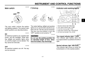
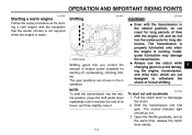
... . The key can be started. Neutral indicator light "NEUTRAL" Turn signal indicator light "TURN" Fuel level warning light "FUEL" High beam indicator light "HIGH BEAM" Oil level warning light "OIL LEVEL" EAU11040 CAUTION: Do not use the parking position for an extended length of time, otherwise the battery may discharge. INSTRUMENT AND CONTROL FUNCTIONS EAU10450 EAU10821 EAU11000 Main switch P (Parking) Indicator and warning lights 3 The main switch controls the ignition and lighting systems. The various main switch positions are supplied with power, and the headlight, meter lighting...
... . The key can be started. Neutral indicator light "NEUTRAL" Turn signal indicator light "TURN" Fuel level warning light "FUEL" High beam indicator light "HIGH BEAM" Oil level warning light "OIL LEVEL" EAU11040 CAUTION: Do not use the parking position for an extended length of time, otherwise the battery may discharge. INSTRUMENT AND CONTROL FUNCTIONS EAU10450 EAU10821 EAU11000 Main switch P (Parking) Indicator and warning lights 3 The main switch controls the ignition and lighting systems. The various main switch positions are supplied with power, and the headlight, meter lighting...
Owners Manual
Page 18
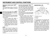
... the engine stop switch to "RUN" and turn the key to "ON". 2. Shift the transmission into the neutral position or pull the clutch lever. 3. Push the start switch. Push the start switch. Odometer 3. The speedometer shows riding speed. This information will enable you to the following procedure. 1. If the warning light does not come on, have a Yamaha dealer check the electrical circuit. The electrical circuit of fuel. Speedometer unit 1. INSTRUMENT AND CONTROL...
... the engine stop switch to "RUN" and turn the key to "ON". 2. Shift the transmission into the neutral position or pull the clutch lever. 3. Push the start switch. Push the start switch. Odometer 3. The speedometer shows riding speed. This information will enable you to the following procedure. 1. If the warning light does not come on, have a Yamaha dealer check the electrical circuit. The electrical circuit of fuel. Speedometer unit 1. INSTRUMENT AND CONTROL...
Owners Manual
Page 19
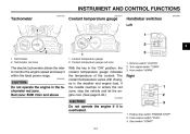
... to monitor the engine speed and keep it is overheated. 1. Tachometer red zone 1. Red zone: 8500 r/min and above With the key in the "ON" position, the coolant temperature gauge indicates the temperature of the coolant. Tachometer 2. If the needle reaches or enters the red zone, stop switch "ENGINE STOP" 2. INSTRUMENT AND CONTROL FUNCTIONS EAU11851 EAU12171 EAU12341 Tachometer Coolant temperature gauge Handlebar switches Left 3 1. Turn signal switch "TURN" 3.
... to monitor the engine speed and keep it is overheated. 1. Tachometer red zone 1. Red zone: 8500 r/min and above With the key in the "ON" position, the coolant temperature gauge indicates the temperature of the coolant. Tachometer 2. If the needle reaches or enters the red zone, stop switch "ENGINE STOP" 2. INSTRUMENT AND CONTROL FUNCTIONS EAU11851 EAU12171 EAU12341 Tachometer Coolant temperature gauge Handlebar switches Left 3 1. Turn signal switch "TURN" 3.
Owners Manual
Page 20
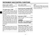
... throttle cable is equipped with the starter. To signal a left . Since this switch should be canceled manually by pushing the switch in the fuel tank. EAU12650 3 Turn signal switch "TURN" To signal a right-hand turn signal lights will not self-cancel while you are stopped at an intersection. INSTRUMENT AND CONTROL FUNCTIONS EAU12410 EAU12510 Dimmer switch "LIGHTS" Set the switch to "HI" for the high beam and to the right. EAU12420 Horn switch "HORN...
... throttle cable is equipped with the starter. To signal a left . Since this switch should be canceled manually by pushing the switch in the fuel tank. EAU12650 3 Turn signal switch "TURN" To signal a right-hand turn signal lights will not self-cancel while you are stopped at an intersection. INSTRUMENT AND CONTROL FUNCTIONS EAU12410 EAU12510 Dimmer switch "LIGHTS" Set the switch to "HI" for the high beam and to the right. EAU12420 Horn switch "HORN...
Owners Manual
Page 23
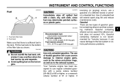
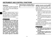
INSTRUMENT AND CONTROL FUNCTIONS EAU13210 ECA10070 Fuel CAUTION: Immediately wipe off spilled fuel with a pump octane number [(R+M)/2] of 86 or higher, or a research octane number of leaded gasoline will extend spark plug life and reduce maintenance costs. EWA10880 Recommended fuel: UNLEADED GASOLINE ONLY Fuel tank capacity: 15.0 L (3.96 us.gal) (3.30 imp.gal) Fuel reserve amount: 3.0 L (0.79 us.gal) (0.66 imp.gal) ECA11400 knocking (or pinging...
INSTRUMENT AND CONTROL FUNCTIONS EAU13210 ECA10070 Fuel CAUTION: Immediately wipe off spilled fuel with a pump octane number [(R+M)/2] of 86 or higher, or a research octane number of leaded gasoline will extend spark plug life and reduce maintenance costs. EWA10880 Recommended fuel: UNLEADED GASOLINE ONLY Fuel tank capacity: 15.0 L (3.96 us.gal) (3.30 imp.gal) Fuel reserve amount: 3.0 L (0.79 us.gal) (0.66 imp.gal) ECA11400 knocking (or pinging...
Owners Manual
Page 30
... the running engine when the transmission is in gear and the clutch lever is pulled, but the clutch lever is not pulled. Periodically check the operation of the frame. G It prevents starting off. EWA10260 3 WARNING The vehicle must be properly moved up (or does not stay up , but the sidestand is still down for an explanation of control. EAU15321 Ignition circuit...
... the running engine when the transmission is in gear and the clutch lever is pulled, but the clutch lever is not pulled. Periodically check the operation of the frame. G It prevents starting off. EWA10260 3 WARNING The vehicle must be properly moved up (or does not stay up , but the sidestand is still down for an explanation of control. EAU15321 Ignition circuit...
Owners Manual
Page 34
... necessary. • Check operation of ignition circuit cut-off system. • If system is smooth. • Lubricate if necessary Check for leakage. Check tire condition and tread depth. Correct if necessary. 6-19, 6-27 4 Control cables 6-27 Wheels and tires 6-19, 6-21 Brake and shift pedals Brake and clutch levers Centerstand, sidestand Chassis fasteners Instruments, lights, signals and switches Sidestand switch Battery • Make sure that operation...
... necessary. • Check operation of ignition circuit cut-off system. • If system is smooth. • Lubricate if necessary Check for leakage. Check tire condition and tread depth. Correct if necessary. 6-19, 6-27 4 Control cables 6-27 Wheels and tires 6-19, 6-21 Brake and shift pedals Brake and clutch levers Centerstand, sidestand Chassis fasteners Instruments, lights, signals and switches Sidestand switch Battery • Make sure that operation...
Owners Manual
Page 35
... a Yamaha dealer check the electrical circuit. 3. Consult a Yamaha dealer regarding any control or function that the sidestand is in the neutral position. Turn the starter (choke) on when the start the engine or operate it could contact the ground and distract the operator, resulting in the neutral position, the neutral indicator light should be as short as possible. 5-1 CAUTION: G The oil level warning light and fuel level warning light...
... a Yamaha dealer check the electrical circuit. 3. Consult a Yamaha dealer regarding any control or function that the sidestand is in the neutral position. Turn the starter (choke) on when the start the engine or operate it could contact the ground and distract the operator, resulting in the neutral position, the neutral indicator light should be as short as possible. 5-1 CAUTION: G The oil level warning light and fuel level warning light...
Owners Manual
Page 37
... transmission into first gear. Open the throttle gradually, and at the same time, release the clutch lever slowly. 5-3 The gear positions are not designed to disengage the clutch. 2. Shift the transmission into the neutral position, press the shift pedal down repeatedly until it reaches the end of its travel, and then slightly raise it. Shift pedal Shifting gears lets you control the amount of engine power available for starting a cold engine...
... transmission into first gear. Open the throttle gradually, and at the same time, release the clutch lever slowly. 5-3 The gear positions are not designed to disengage the clutch. 2. Shift the transmission into the neutral position, press the shift pedal down repeatedly until it reaches the end of its travel, and then slightly raise it. Shift pedal Shifting gears lets you control the amount of engine power available for starting a cold engine...
Owners Manual
Page 42
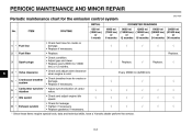
... engine idle speed. • Check for the emission control system INITIAL No. Replace. 6 4 * Valve clearance Crankcase breather system Carburetor synchronization Idle speed Every 26600 mi (42000 km 5 * 6 * 7 * 8 * Exhaust system * Since these items require special tools, data and technical skills, have a Yamaha dealer perform the service. 6-3 PERIODIC MAINTENANCE AND MINOR REPAIR EAU17600 Periodic maintenance chart for leakage. • Tighten if necessary. • Replace gasket(s) if necessary. √ √ 3 Spark plugs Replace...
... engine idle speed. • Check for the emission control system INITIAL No. Replace. 6 4 * Valve clearance Crankcase breather system Carburetor synchronization Idle speed Every 26600 mi (42000 km 5 * 6 * 7 * 8 * Exhaust system * Since these items require special tools, data and technical skills, have a Yamaha dealer perform the service. 6-3 PERIODIC MAINTENANCE AND MINOR REPAIR EAU17600 Periodic maintenance chart for leakage. • Tighten if necessary. • Replace gasket(s) if necessary. √ √ 3 Spark plugs Replace...
Owners Manual
Page 59
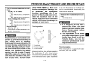
... can shift. Securely pack your vehicle, such as handling, braking, performance and safety. It is important for several characteristics of your heaviest items close to the center of your tires. Tire sidewall 2. Tire inspection in ) EWA10580 WARNING G G WARNING Proper loading of the vehicle, and distribute the weight evenly from side to ride with tubeless tires, and cast wheels. Tire wear indicator 3. Operation of rider, passenger, cargo and accessories EWA10510...
... can shift. Securely pack your vehicle, such as handling, braking, performance and safety. It is important for several characteristics of your heaviest items close to the center of your tires. Tire sidewall 2. Tire inspection in ) EWA10580 WARNING G G WARNING Proper loading of the vehicle, and distribute the weight evenly from side to ride with tubeless tires, and cast wheels. Tire wear indicator 3. Operation of rider, passenger, cargo and accessories EWA10510...
Owners Manual
Page 73
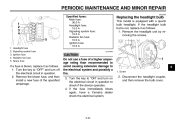
... fuse of a higher amperage rating than recommended to avoid causing extensive damage to check if the device operates. 4. Headlight fuse Signaling system fuse Ignition fuse Radiator fan fuse Spare fuse Specified fuses: Main fuse: 30.0 A Headlight fuse: 15.0 A Signaling system fuse: 10.0 A Radiator fan fuse: 10.0 A Ignition fuse: 10.0 A ECA10640 Replacing the headlight bulb This model is blown, replace it as follows. 1. Screw 2. Turn the key to "ON" and turn off the electrical circuit in question to the electrical system and possibly a fire. 3. Turn the key...
... fuse of a higher amperage rating than recommended to avoid causing extensive damage to check if the device operates. 4. Headlight fuse Signaling system fuse Ignition fuse Radiator fan fuse Spare fuse Specified fuses: Main fuse: 30.0 A Headlight fuse: 15.0 A Signaling system fuse: 10.0 A Radiator fan fuse: 10.0 A Ignition fuse: 10.0 A ECA10640 Replacing the headlight bulb This model is blown, replace it as follows. 1. Screw 2. Turn the key to "ON" and turn off the electrical circuit in question to the electrical system and possibly a fire. 3. Turn the key...
Owners Manual
Page 85
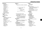
... :1 Starting system: Electric starter Lubrication system: Wet sump Recommended engine oil grade: API service SE, SF, SG type or higher Engine oil quantity: Without oil filter cartridge replacement: 3.50 L (3.70 us.qt) (3.08 Imp.qt) With oil filter cartridge replacement: 3.80 L (4.02 us.qt) (3.34 Imp.qt) Spark plug(s): Manufacturer/model: NGK/DPR8EA-9 Manufacturer/model: DENSO/X24EPR-U9 Spark plug gap: 0.8-0.9 mm (0.031-0.035 in) Final gear oil: Type: SAE80API "GL-4" hypoid gear oil...
... :1 Starting system: Electric starter Lubrication system: Wet sump Recommended engine oil grade: API service SE, SF, SG type or higher Engine oil quantity: Without oil filter cartridge replacement: 3.50 L (3.70 us.qt) (3.08 Imp.qt) With oil filter cartridge replacement: 3.80 L (4.02 us.qt) (3.34 Imp.qt) Spark plug(s): Manufacturer/model: NGK/DPR8EA-9 Manufacturer/model: DENSO/X24EPR-U9 Spark plug gap: 0.8-0.9 mm (0.031-0.035 in) Final gear oil: Type: SAE80API "GL-4" hypoid gear oil...
Owners Manual
Page 87
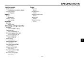
... Fuses: Main fuse: 30.0 A Headlight fuse: 15.0 A Signaling system fuse: 10.0 A Ignition fuse: 10.0 A Radiator fan fuse: 10.0 A Battery: Model: YB16AL-A2 Voltage, capacity: 12 V, 16.0 Ah Headlight: Bulb type: Halogen bulb Bulb voltage, wattage x quantity: Headlight: 12 V, 60.0 W/55.0 W × 1 Tail/brake light: 12 V, 8.0 W/27.0 W × 2 Front turn signal/position light: 12 V-27.0 W/8.0 W × 2 Rear turn signal light: 12 V, 27.0 W × 2 Meter lighting: 14 V, 3.0 W × 2 Neutral indicator light: 14 V, 3.0 W × 1 High beam indicator light: 14 V, 3.0 W × 1 Oil level warning...
... Fuses: Main fuse: 30.0 A Headlight fuse: 15.0 A Signaling system fuse: 10.0 A Ignition fuse: 10.0 A Radiator fan fuse: 10.0 A Battery: Model: YB16AL-A2 Voltage, capacity: 12 V, 16.0 Ah Headlight: Bulb type: Halogen bulb Bulb voltage, wattage x quantity: Headlight: 12 V, 60.0 W/55.0 W × 1 Tail/brake light: 12 V, 8.0 W/27.0 W × 2 Front turn signal/position light: 12 V-27.0 W/8.0 W × 2 Rear turn signal light: 12 V, 27.0 W × 2 Meter lighting: 14 V, 3.0 W × 2 Neutral indicator light: 14 V, 3.0 W × 1 High beam indicator light: 14 V, 3.0 W × 1 Oil level warning...
Owners Manual
Page 98
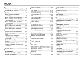
INDEX A Accessories and replacement parts...6-22 Air filter element, cleaning...6-17 Engine stop switch...3-4 Noise regulation ...9-4 F Final gear oil ...6-13 Front and rear brake pads, checking...6-25 Front fork, adjusting...3-10 Front fork, checking ...6-29 Fuel...3-7 Fuel level warning light ...3-2 Fuel reserve switch...3-4 Fuel tank cap ...3-6 Fuses, replacing ...6-33 O Oil level warning light ...3-2 B Battery...6-31 Brake and clutch fluid levels, checking ...6-25 Brake and clutch fluids, changing ...6-26 Brake and clutch levers, checking and lubricating ...6-28 Brake and shift pedals, ...
INDEX A Accessories and replacement parts...6-22 Air filter element, cleaning...6-17 Engine stop switch...3-4 Noise regulation ...9-4 F Final gear oil ...6-13 Front and rear brake pads, checking...6-25 Front fork, adjusting...3-10 Front fork, checking ...6-29 Fuel...3-7 Fuel level warning light ...3-2 Fuel reserve switch...3-4 Fuel tank cap ...3-6 Fuses, replacing ...6-33 O Oil level warning light ...3-2 B Battery...6-31 Brake and clutch fluid levels, checking ...6-25 Brake and clutch fluids, changing ...6-26 Brake and clutch levers, checking and lubricating ...6-28 Brake and shift pedals, ...