
Owners Manual
Page 12
... mounting accessories. 1. When loading within this motorcycle. Make sure that accessories and cargo are securely attached to the motorcycle before using it does not in any way reduce ground clearance or cornering clearance, limit suspension travel, steering travel or control operation, or obscure lights or reflectors. 1 1-4 Cargo and accessory weight should be responsible for use of non-Yamaha accessories. Shifting weights can create unstable handling...
... mounting accessories. 1. When loading within this motorcycle. Make sure that accessories and cargo are securely attached to the motorcycle before using it does not in any way reduce ground clearance or cornering clearance, limit suspension travel, steering travel or control operation, or obscure lights or reflectors. 1 1-4 Cargo and accessory weight should be responsible for use of non-Yamaha accessories. Shifting weights can create unstable handling...
Owners Manual
Page 13
... movement of lights or engine power. 1 Gasoline and exhaust gas 1. Use caution when adding electrical accessories. If electrical accessories exceed the capacity of the motorcycle's electrical system, an electric failure could result, which could cause a dangerous loss of the operator and may limit control ability, therefore, such accessories are poisonous and may also cause instability when passing or being passed by large vehicles. If accessories are...
... movement of lights or engine power. 1 Gasoline and exhaust gas 1. Use caution when adding electrical accessories. If electrical accessories exceed the capacity of the motorcycle's electrical system, an electric failure could result, which could cause a dangerous loss of the operator and may limit control ability, therefore, such accessories are poisonous and may also cause instability when passing or being passed by large vehicles. If accessories are...
Owners Manual
Page 24
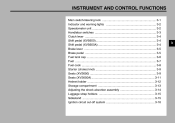
INSTRUMENT AND CONTROL FUNCTIONS Main switch/steering lock ...3-1 Indicator and warning lights ...3-2 Speedometer unit ...3-2 Handlebar switches ...3-3 Clutch lever ...3-4 Shift pedal (XVS650)...3-4 Shift pedal (XVS650A) ...3-4 Brake lever ...3-5 Brake pedal ...3-5 Fuel tank cap ...3-6 Fuel ...3-7 Fuel cock ...3-8 Starter (choke) knob ...3-9 Seats (XVS650) ...3-9 Seats (XVS650A) ...3-11 Helmet holder ...3-12 Storage compartment ...3-13 Adjusting the shock absorber assembly ...3-14 Luggage strap holders ...3-15 Sidestand ...3-15 Ignition circuit cut-off system ...3-16 3
INSTRUMENT AND CONTROL FUNCTIONS Main switch/steering lock ...3-1 Indicator and warning lights ...3-2 Speedometer unit ...3-2 Handlebar switches ...3-3 Clutch lever ...3-4 Shift pedal (XVS650)...3-4 Shift pedal (XVS650A) ...3-4 Brake lever ...3-5 Brake pedal ...3-5 Fuel tank cap ...3-6 Fuel ...3-7 Fuel cock ...3-8 Starter (choke) knob ...3-9 Seats (XVS650) ...3-9 Seats (XVS650A) ...3-11 Helmet holder ...3-12 Storage compartment ...3-13 Adjusting the shock absorber assembly ...3-14 Luggage strap holders ...3-15 Sidestand ...3-15 Ignition circuit cut-off system ...3-16 3

Owners Manual
Page 25
To lock the steering 1. Turn the handlebars all electrical systems are supplied with power, the headlight, meter lighting, taillight and front position lights come on, and the engine can be removed. The key cannot be switched off, which may result in loss of control or an accident. EAU00038 WARNING Never turn the key to "OFF" while still pushing it to "OFF" or "LOCK" while the motorcycle is...
To lock the steering 1. Turn the handlebars all electrical systems are supplied with power, the headlight, meter lighting, taillight and front position lights come on, and the engine can be removed. The key cannot be switched off, which may result in loss of control or an accident. EAU00038 WARNING Never turn the key to "OFF" while still pushing it to "OFF" or "LOCK" while the motorcycle is...
Owners Manual
Page 26
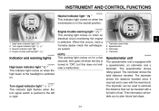
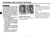
..., have a Yamaha dealer check the self-diagnosis system. High beam indicator light " " Turn signal indicator light " " Neutral indicator light " " Engine trouble warning light " " EAU03034 Engine trouble warning light " " This warning light comes on when an electrical circuit monitoring the engine is switched on. NOTE: This warning light comes on for a few seconds, then goes off when the key is in the neutral position. This information will enable you to plan future fuel stops...
..., have a Yamaha dealer check the self-diagnosis system. High beam indicator light " " Turn signal indicator light " " Neutral indicator light " " Engine trouble warning light " " EAU03034 Engine trouble warning light " " This warning light comes on when an electrical circuit monitoring the engine is switched on. NOTE: This warning light comes on for a few seconds, then goes off when the key is in the neutral position. This information will enable you to plan future fuel stops...
Owners Manual
Page 27
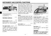
... beam. Start switch " " / " EAU03890 EAU00129 Turn signal switch " / " To signal a right-hand turn signal lights can also be canceled manually by pushing the switch in case of an emergency, such as when the motorcycle overturns or when the throttle cable is stuck. Dimmer switch " / 2. Set this switch to " " to " ". INSTRUMENT AND CONTROL FUNCTIONS Since this model is equipped with the starter. EAU00143 Start switch " " Push this switch to crank the engine with...
... beam. Start switch " " / " EAU03890 EAU00129 Turn signal switch " / " To signal a right-hand turn signal lights can also be canceled manually by pushing the switch in case of an emergency, such as when the motorcycle overturns or when the throttle cable is stuck. Dimmer switch " / 2. Set this switch to " " to " ". INSTRUMENT AND CONTROL FUNCTIONS Since this model is equipped with the starter. EAU00143 Start switch " " Push this switch to crank the engine with...
Owners Manual
Page 31
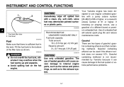
... Fuel Make sure that containing methanol. Gasohol containing ethanol can cause damage to the exhaust system. _ _ 3-7 The use a gasoline of gasohol: gasohol containing ethanol and that there is not recommended by Yamaha because it may deteriorate painted surfaces or plastic parts. @ @ EAU04265 3 1. Fill the fuel tank to the bottom of leaded gasoline will extend spark plug life and reduce maintenance...
... Fuel Make sure that containing methanol. Gasohol containing ethanol can cause damage to the exhaust system. _ _ 3-7 The use a gasoline of gasohol: gasohol containing ethanol and that there is not recommended by Yamaha because it may deteriorate painted surfaces or plastic parts. @ @ EAU04265 3 1. Fill the fuel tank to the bottom of leaded gasoline will extend spark plug life and reduce maintenance...
Owners Manual
Page 39
... the gas cylinder. NOTE: The built-in sidestand switch is part of the ignition circuit cut-off system, which cuts the ignition in poor damping performance. Raise the sidestand or lower it may result from improper handling. The manufacturer cannot be held responsible for an explanation of the frame. INSTRUMENT AND CONTROL FUNCTIONS EAU00315 EAU00330 3 WARNING This shock absorber contains highly pressurized nitrogen gas.
... the gas cylinder. NOTE: The built-in sidestand switch is part of the ignition circuit cut-off system, which cuts the ignition in poor damping performance. Raise the sidestand or lower it may result from improper handling. The manufacturer cannot be held responsible for an explanation of the frame. INSTRUMENT AND CONTROL FUNCTIONS EAU00315 EAU00330 3 WARNING This shock absorber contains highly pressurized nitrogen gas.
Owners Manual
Page 44
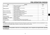
PAGE 6-27 Wheels and tires 6-17-6-19 Brake and shift pedals Brake and clutch levers Sidestand Chassis fasteners Instruments, lights, signals and switches Sidestand switch • Make sure that operation is smooth. • Lubricate pedal pivoting points if ...more than worth the time involved. @ @ EWA00033 WARNING If any item in a very short time; Check air pressure. Check tire condition and tread depth. Correct if necessary. Such an inspection can be accomplished in the Pre-operation check list is not working properly, have Yamaha dealer check vehicle. 6-28 6-28 6-...
PAGE 6-27 Wheels and tires 6-17-6-19 Brake and shift pedals Brake and clutch levers Sidestand Chassis fasteners Instruments, lights, signals and switches Sidestand switch • Make sure that operation is smooth. • Lubricate pedal pivoting points if ...more than worth the time involved. @ @ EWA00033 WARNING If any item in a very short time; Check air pressure. Check tire condition and tread depth. Correct if necessary. Such an inspection can be accomplished in the Pre-operation check list is not working properly, have Yamaha dealer check vehicle. 6-28 6-28 6-...
Owners Manual
Page 46
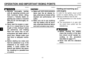
... starting, one of time. EW000054 @ _ WARNING Before starting out, make sure that there is up a cold engine In order for any control or function that the sidestand is adequate ventilation. OPERATION AND IMPORTANT RIDING POINTS EAU00373 EAU00376 EAU00372 EAU04219* @ 5 WARNING Become thoroughly familiar with the sidestand down. Consult a Yamaha dealer regarding any length of the following conditions must be blocked and performance...
... starting, one of time. EW000054 @ _ WARNING Before starting out, make sure that there is up a cold engine In order for any control or function that the sidestand is adequate ventilation. OPERATION AND IMPORTANT RIDING POINTS EAU00373 EAU00376 EAU00372 EAU04219* @ 5 WARNING Become thoroughly familiar with the sidestand down. Consult a Yamaha dealer regarding any length of the following conditions must be blocked and performance...

Owners Manual
Page 47
... engine, and have a Yamaha dealer check the electrical circuit. _ _ _ 4. ECA00055 5 CAUTION: For maximum engine life, always warm the engine up before starting off . 5-2 Turn the fuel cock lever to preserve the battery. Do not crank the engine more than 10 seconds on and completely close the throttle. (See page 3-9 for starter (choke) operation.) 5. When the engine is set to start, release the start switch. If the engine trouble warning light...
... engine, and have a Yamaha dealer check the electrical circuit. _ _ _ 4. ECA00055 5 CAUTION: For maximum engine life, always warm the engine up before starting off . 5-2 Turn the fuel cock lever to preserve the battery. Do not crank the engine more than 10 seconds on and completely close the throttle. (See page 3-9 for starter (choke) operation.) 5. When the engine is set to start, release the start switch. If the engine trouble warning light...
Owners Manual
Page 49
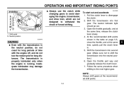
... for long distances. To start out and accelerate 1. The neutral indicator light should go out. 3. NOTE: Always shift gears at the same time, release the clutch lever slowly. 4. Shift pedal N. Inadequate lubrication may damage the transmission. Follow the same procedure when shifting to disengage the clutch. 2. Open the throttle gradually, and at the recommended shift points. @ @ 5 5-4 The transmission is properly lubricated only when the engine is running.
... for long distances. To start out and accelerate 1. The neutral indicator light should go out. 3. NOTE: Always shift gears at the same time, release the clutch lever slowly. 4. Shift pedal N. Inadequate lubrication may damage the transmission. Follow the same procedure when shifting to disengage the clutch. 2. Open the throttle gradually, and at the recommended shift points. @ @ 5 5-4 The transmission is properly lubricated only when the engine is running.
Owners Manual
Page 52
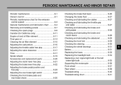
... MINOR REPAIR Periodic maintenance ...6-1 Owner's tool kit ...6-1 Periodic maintenance chart for the emission control system ...6-3 General maintenance and lubrication chart ...6-4 Removing and installing panels ...6-7 Checking the spark plugs ...6-9 Canister (for California only) ...6-11 Engine oil and oil filter element ...6-11 Final gear oil ...6-14 Cleaning the air filter element ...6-15 Adjusting the carburetors ...6-16 Adjusting the throttle cable free play ...6-17 Adjusting the valve clearance ...6-17 Tires ...6-17 Spoke wheels ...6-19 Accessories and replacement...
... MINOR REPAIR Periodic maintenance ...6-1 Owner's tool kit ...6-1 Periodic maintenance chart for the emission control system ...6-3 General maintenance and lubrication chart ...6-4 Removing and installing panels ...6-7 Checking the spark plugs ...6-9 Canister (for California only) ...6-11 Engine oil and oil filter element ...6-11 Final gear oil ...6-14 Cleaning the air filter element ...6-15 Adjusting the carburetors ...6-16 Adjusting the throttle cable free play ...6-17 Adjusting the valve clearance ...6-17 Tires ...6-17 Spoke wheels ...6-19 Accessories and replacement...
Owners Manual
Page 55
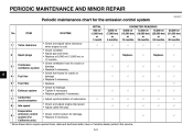
.... • Replace gasket(s) if necessary. • Adjust synchronization of carburetors. • Check and adjust engine idle speed. • Adjust cable free play. • Check control system for the emission control system INITIAL No. PERIODIC MAINTENANCE AND MINOR REPAIR EAU00471 Periodic maintenance chart for damage. • Replace if necessary. 2 Spark plugs √ Replace. √ Replace. √ 3 * Crankcase ventilation system √ √ √ √ √ 6 4 * 5 * 6 * 7 * 8 * Fuel line Fuel filter Exhaust system...
.... • Replace gasket(s) if necessary. • Adjust synchronization of carburetors. • Check and adjust engine idle speed. • Adjust cable free play. • Check control system for the emission control system INITIAL No. PERIODIC MAINTENANCE AND MINOR REPAIR EAU00471 Periodic maintenance chart for damage. • Replace if necessary. 2 Spark plugs √ Replace. √ Replace. √ 3 * Crankcase ventilation system √ √ √ √ √ 6 4 * 5 * 6 * 7 * 8 * Fuel line Fuel filter Exhaust system...
Owners Manual
Page 76
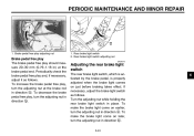
..., adjust the brake light switch as follows. PERIODIC MAINTENANCE AND MINOR REPAIR 1. To make the brake light come on earlier, turn the adjusting nut in direction a. To make the brake light come on just before braking takes effect. To decrease the brake pedal free play should measure 20-30 mm (0.79-1.18 in direction b. 1. Rear brake light switch adjusting nut EAU00713 Adjusting the rear brake light switch The rear brake light switch, which is...
..., adjust the brake light switch as follows. PERIODIC MAINTENANCE AND MINOR REPAIR 1. To make the brake light come on earlier, turn the adjusting nut in direction a. To make the brake light come on just before braking takes effect. To decrease the brake pedal free play should measure 20-30 mm (0.79-1.18 in direction b. 1. Rear brake light switch adjusting nut EAU00713 Adjusting the rear brake light switch The rear brake light switch, which is...
Owners Manual
Page 85
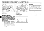
... installation procedures.) If a fuse is blown, replace it as follows. 1. Turn the key to "OFF" and turn on the electrical circuit in question. 2. PERIODIC MAINTENANCE AND MINOR REPAIR EC000103 CAUTION: Do not use a fuse of the specified amperage. 1. 2. 3. 4. 5. Turn the key to "ON" and turn off the electrical circuit in question to the electrical system and possibly a fire. _ _ 1. Main fuse 3. Ignition fuse Signaling system fuse Headlight fuse Carburetor heater fuse Spare fuse (× 2) 3. Remove the...
... installation procedures.) If a fuse is blown, replace it as follows. 1. Turn the key to "OFF" and turn on the electrical circuit in question. 2. PERIODIC MAINTENANCE AND MINOR REPAIR EC000103 CAUTION: Do not use a fuse of the specified amperage. 1. 2. 3. 4. 5. Turn the key to "ON" and turn off the electrical circuit in question to the electrical system and possibly a fire. _ _ 1. Main fuse 3. Ignition fuse Signaling system fuse Headlight fuse Carburetor heater fuse Spare fuse (× 2) 3. Remove the...
Owners Manual
Page 91
... axle nut, the final gear case bolts and the brake torque rod bolt to the swingarm. 7. Middle gear universal joint 2. Install the rear wheel, wheel axle, final gear case, and drive shaft by pushing the wheel forward and guiding the drive shaft into the middle gear universal joint. 2. Final gear case 1. NOTE: Make sure to support the drive shaft as an assembly: wheel, wheel axle, final gear case, and drive shaft. PERIODIC MAINTENANCE AND MINOR REPAIR 3. Install the brake...
... axle nut, the final gear case bolts and the brake torque rod bolt to the swingarm. 7. Middle gear universal joint 2. Install the rear wheel, wheel axle, final gear case, and drive shaft by pushing the wheel forward and guiding the drive shaft into the middle gear universal joint. 2. Final gear case 1. NOTE: Make sure to support the drive shaft as an assembly: wheel, wheel axle, final gear case, and drive shaft. PERIODIC MAINTENANCE AND MINOR REPAIR 3. Install the brake...
Owners Manual
Page 105
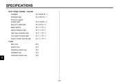
SPECIFICATIONS Bulb voltage, wattage × quantity Headlight Tail/brake light Front turn signal/ position light Rear turn signal light Meter lighting Neutral indicator light High beam indicator light Turn signal indicator light Engine trouble warning light Fuses Main fuse Ignition fuse Signaling system fuse Headlight fuse Carburetor heater fuse 30 A 10 A 10 A 15 A 15 A 12 V, 60/55 W × 1 12 V, 8/27 W × 1 12 V, 27/8 W × 2 12 V, 27 W × 2 12 V, 1.7 W × 1 12 V, 1.7 W × 1 12 V, 1.7 W × 1 12 V, 1.7 W × 1 12 V, 1.7 W × 1 8 8-5
SPECIFICATIONS Bulb voltage, wattage × quantity Headlight Tail/brake light Front turn signal/ position light Rear turn signal light Meter lighting Neutral indicator light High beam indicator light Turn signal indicator light Engine trouble warning light Fuses Main fuse Ignition fuse Signaling system fuse Headlight fuse Carburetor heater fuse 30 A 10 A 10 A 15 A 15 A 12 V, 60/55 W × 1 12 V, 8/27 W × 1 12 V, 27/8 W × 2 12 V, 27 W × 2 12 V, 1.7 W × 1 12 V, 1.7 W × 1 12 V, 1.7 W × 1 12 V, 1.7 W × 1 12 V, 1.7 W × 1 8 8-5
Owners Manual
Page 117
... Maintenance record ...9-5 Model label ...9-2 B Battery ...6-31 Brake and clutch levers, checking and lubricating ...6-28 Brake and shift pedals, checking and lubricating ...6-28 Brake fluid, changing ...6-27 Brake fluid level, checking...6-26 Brake lever...3-5 Brake lever free play, adjusting ...6-22 Brake light switch (rear), adjusting ...6-24 Brake pads and shoes, checking ...6-25 Brake pedal...3-5 Brake pedal position and free play, adjusting ...6-23 F Final gear oil...6-14 Front fork, checking ...6-29 Fuel ...3-7 Fuel cock...3-8 Fuel tank cap...3-6 Fuses, replacing ...6-33 N Neutral...
... Maintenance record ...9-5 Model label ...9-2 B Battery ...6-31 Brake and clutch levers, checking and lubricating ...6-28 Brake and shift pedals, checking and lubricating ...6-28 Brake fluid, changing ...6-27 Brake fluid level, checking...6-26 Brake lever...3-5 Brake lever free play, adjusting ...6-22 Brake light switch (rear), adjusting ...6-24 Brake pads and shoes, checking ...6-25 Brake pedal...3-5 Brake pedal position and free play, adjusting ...6-23 F Final gear oil...6-14 Front fork, checking ...6-29 Fuel ...3-7 Fuel cock...3-8 Fuel tank cap...3-6 Fuses, replacing ...6-33 N Neutral...
Owners Manual
Page 118
...36 V Valve clearance, adjusting ...6-17 Vehicle identification number...9-1 W Warranty, extended...9-9 Warranty limited ...9-7 Wheel bearings, checking ...6-31 Wheel (front) ...6-37 Installing ...6-37 Removing ...6-37 Wheel (rear) ...6-38 Installing ...6-39 Removing ...6-38 Wheels...6-19 T Throttle cable free play, adjusting ...6-17 Throttle grip and cable, checking and lubricating...6-27 Tires ...6-17 Tool kit...6-1 Troubleshooting...6-40 Troubleshooting chart...6-41 Turn signal indicator light ...3-2 Turn signal light or tail/brake light bulb, replacing ...6-35 Turn signal switch...3-3
...36 V Valve clearance, adjusting ...6-17 Vehicle identification number...9-1 W Warranty, extended...9-9 Warranty limited ...9-7 Wheel bearings, checking ...6-31 Wheel (front) ...6-37 Installing ...6-37 Removing ...6-37 Wheel (rear) ...6-38 Installing ...6-39 Removing ...6-38 Wheels...6-19 T Throttle cable free play, adjusting ...6-17 Throttle grip and cable, checking and lubricating...6-27 Tires ...6-17 Tool kit...6-1 Troubleshooting...6-40 Troubleshooting chart...6-41 Turn signal indicator light ...3-2 Turn signal light or tail/brake light bulb, replacing ...6-35 Turn signal switch...3-3