

Owners Manual
Page 12
... Yamaha cannot test all other accessories that would impair the performance of your motorcycle. Keep the following in mind, as well as those provided under "Loading" when mounting accessories. 1. Carefully inspect the accessory before riding. Check accessory mounts and cargo restraints frequently. 3. Cargo and accessory weight should be responsible for use of non-Yamaha accessories. SAFETY INFORMATION Loading The total weight of the operator, passenger, accessories...
... Yamaha cannot test all other accessories that would impair the performance of your motorcycle. Keep the following in mind, as well as those provided under "Loading" when mounting accessories. 1. Carefully inspect the accessory before riding. Check accessory mounts and cargo restraints frequently. 3. Cargo and accessory weight should be responsible for use of non-Yamaha accessories. SAFETY INFORMATION Loading The total weight of the operator, passenger, accessories...
Owners Manual
Page 13
... electrical accessories exceed the capacity of the motorcycle's electrical system, an electric failure could result, which could cause a dangerous loss of consciousness and death within a short time. Take care not to spill any length of the motorcycle due to aerodynamic effects. The exhaust fumes are poisonous and may cause loss of lights or engine power. 1 Gasoline and exhaust gas 1. b. Use caution when adding electrical accessories...
... electrical accessories exceed the capacity of the motorcycle's electrical system, an electric failure could result, which could cause a dangerous loss of consciousness and death within a short time. Take care not to spill any length of the motorcycle due to aerodynamic effects. The exhaust fumes are poisonous and may cause loss of lights or engine power. 1 Gasoline and exhaust gas 1. b. Use caution when adding electrical accessories...

Owners Manual
Page 24
INSTRUMENT AND CONTROL FUNCTIONS Main switch/steering lock ...3-1 Indicator and warning lights ...3-2 Speedometer unit ...3-2 Handlebar switches ...3-3 Clutch lever ...3-4 Shift pedal (XVS650)...3-4 Shift pedal (XVS650A) ...3-4 Brake lever ...3-5 Brake pedal ...3-5 Fuel tank cap ...3-6 Fuel ...3-7 Fuel cock ...3-8 Starter (choke) knob ...3-9 Seats (XVS650) ...3-9 Seats (XVS650A) ...3-11 Helmet holder ...3-12 Storage compartment ...3-13 Adjusting the shock absorber assembly ...3-14 Luggage strap holders ...3-15 Sidestand ...3-15 Ignition circuit cut-off system ...3-16 3
INSTRUMENT AND CONTROL FUNCTIONS Main switch/steering lock ...3-1 Indicator and warning lights ...3-2 Speedometer unit ...3-2 Handlebar switches ...3-3 Clutch lever ...3-4 Shift pedal (XVS650)...3-4 Shift pedal (XVS650A) ...3-4 Brake lever ...3-5 Brake pedal ...3-5 Fuel tank cap ...3-6 Fuel ...3-7 Fuel cock ...3-8 Starter (choke) knob ...3-9 Seats (XVS650) ...3-9 Seats (XVS650A) ...3-11 Helmet holder ...3-12 Storage compartment ...3-13 Adjusting the shock absorber assembly ...3-14 Luggage strap holders ...3-15 Sidestand ...3-15 Ignition circuit cut-off system ...3-16 3

Owners Manual
Page 25
... key to "OFF" or "LOCK". @ @ OFF All electrical systems are off. Turn. EW000016 EAU00029 EAU00040 Main switch/steering lock The main switch/steering lock controls the ignition and lighting systems, and is locked, and all the way to "LOCK" while still pushing it . 3-1 ON All electrical systems are described below. The various positions are supplied with power, the headlight, meter lighting, taillight and front position lights come on, and the engine...
... key to "OFF" or "LOCK". @ @ OFF All electrical systems are off. Turn. EW000016 EAU00029 EAU00040 Main switch/steering lock The main switch/steering lock controls the ignition and lighting systems, and is locked, and all the way to "LOCK" while still pushing it . 3-1 ON All electrical systems are described below. The various positions are supplied with power, the headlight, meter lighting, taillight and front position lights come on, and the engine...
Owners Manual
Page 26
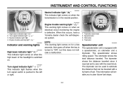
... be used to "ON", but this occurs, have a Yamaha dealer check the self-diagnosis system. High beam indicator light " " Turn signal indicator light " " Neutral indicator light " " Engine trouble warning light " " EAU03034 Engine trouble warning light " " This warning light comes on when the transmission is pushed to plan future fuel stops. EAU04243* 1. 2. 3. 4. EAU00057 Turn signal indicator light " " This indicator light flashes when the turn signal switch is in the neutral position. Tripmeter reset knob...
... be used to "ON", but this occurs, have a Yamaha dealer check the self-diagnosis system. High beam indicator light " " Turn signal indicator light " " Neutral indicator light " " Engine trouble warning light " " EAU03034 Engine trouble warning light " " This warning light comes on when the transmission is pushed to plan future fuel stops. EAU04243* 1. 2. 3. 4. EAU00057 Turn signal indicator light " " This indicator light flashes when the turn signal switch is in the neutral position. Tripmeter reset knob...
Owners Manual
Page 27
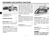
Turn signal switch " 3. Start switch " " / " EAU03890 EAU00129 Turn signal switch " / " To signal a right-hand turn, push this switch to " ". To signal a left-hand turn, push this switch to " ". When released, the switch returns to the center position. Engine stop switch " / " Set this switch to crank the engine with a self-canceling system, the turn signal lights will not selfcancel while you are stopped at an intersection. _ _ 1. INSTRUMENT AND CONTROL FUNCTIONS Since this model is equipped with the starter. EC000005 CAUTION...
Turn signal switch " 3. Start switch " " / " EAU03890 EAU00129 Turn signal switch " / " To signal a right-hand turn, push this switch to " ". To signal a left-hand turn, push this switch to " ". When released, the switch returns to the center position. Engine stop switch " / " Set this switch to crank the engine with a self-canceling system, the turn signal lights will not selfcancel while you are stopped at an intersection. _ _ 1. INSTRUMENT AND CONTROL FUNCTIONS Since this model is equipped with the starter. EC000005 CAUTION...
Owners Manual
Page 31
... exceed 10%. The use of unleaded fuel will cause severe damage to the fuel system or vehicle performance problems. _ WARNING G Do not overfill the fuel tank, otherwise it may deteriorate painted surfaces or plastic parts. @ @ EAU04265 3 1. Fuel level EAU03753 Fuel Make sure that containing methanol. Gasohol containing methanol is sufficient fuel in the tank. Use of leaded gasoline will extend spark plug life and reduce maintenance costs.
... exceed 10%. The use of unleaded fuel will cause severe damage to the fuel system or vehicle performance problems. _ WARNING G Do not overfill the fuel tank, otherwise it may deteriorate painted surfaces or plastic parts. @ @ EAU04265 3 1. Fuel level EAU03753 Fuel Make sure that containing methanol. Gasohol containing methanol is sufficient fuel in the tank. Use of leaded gasoline will extend spark plug life and reduce maintenance costs.

Owners Manual
Page 39
... ignition circuit cut -off system.) @ @ 1. G Always have a Yamaha dealer service the shock absorber. @ @ Sidestand The sidestand is part of the frame. NOTE: The built-in sidestand switch is located on each passenger footrest. 3-15 G Do not subject the shock absorber to an open the gas cylinder. INSTRUMENT AND CONTROL FUNCTIONS EAU00315 EAU00330 3 WARNING This shock absorber contains highly pressurized nitrogen gas. Raise the sidestand or lower...
... ignition circuit cut -off system.) @ @ 1. G Always have a Yamaha dealer service the shock absorber. @ @ Sidestand The sidestand is part of the frame. NOTE: The built-in sidestand switch is located on each passenger footrest. 3-15 G Do not subject the shock absorber to an open the gas cylinder. INSTRUMENT AND CONTROL FUNCTIONS EAU00315 EAU00330 3 WARNING This shock absorber contains highly pressurized nitrogen gas. Raise the sidestand or lower...

Owners Manual
Page 44
.... @ @ 4-2 Check tire condition and tread depth. and the added safety it assures is more than worth the time involved. @ @ EWA00033 WARNING If any item in the Pre-operation check list is smooth. • Lubricate if necessary Check for damage. Check air pressure. PAGE 6-27 Wheels and tires 6-17-6-19 Brake and shift pedals Brake and clutch levers Sidestand Chassis fasteners Instruments, lights, signals and switches Sidestand switch •...
.... @ @ 4-2 Check tire condition and tread depth. and the added safety it assures is more than worth the time involved. @ @ EWA00033 WARNING If any item in the Pre-operation check list is smooth. • Lubricate if necessary Check for damage. Check air pressure. PAGE 6-27 Wheels and tires 6-17-6-19 Brake and shift pedals Brake and clutch levers Sidestand Chassis fasteners Instruments, lights, signals and switches Sidestand switch •...
Owners Manual
Page 46
.... EW000054 @ _ WARNING Before starting the engine, check the function of control. G Never start the engine or operate it could contact the ground and distract the operator, resulting in gear with the clutch lever pulled and the sidestand up . If the sidestand is in a closed area for the ignition circuit cut -off system to store personal items near the battery and its...
.... EW000054 @ _ WARNING Before starting the engine, check the function of control. G Never start the engine or operate it could contact the ground and distract the operator, resulting in gear with the clutch lever pulled and the sidestand up . If the sidestand is in a closed area for the ignition circuit cut -off system to store personal items near the battery and its...
Owners Manual
Page 47
... warning light should be as short as possible to start, release the start switch. When the engine is cold! _ _ 7. Turn the fuel cock lever to "ON", and then go off . 5-2 ECA00055 5 CAUTION: For maximum engine life, always warm the engine up before starting attempt should be on, otherwise have a Yamaha dealer check the self-diagnosis system. _ 1. Shift the transmission into the neutral position. Turn the key to " ". 3. After starting...
... warning light should be as short as possible to start, release the start switch. When the engine is cold! _ _ 7. Turn the fuel cock lever to "ON", and then go off . 5-2 ECA00055 5 CAUTION: For maximum engine life, always warm the engine up before starting attempt should be on, otherwise have a Yamaha dealer check the self-diagnosis system. _ 1. Shift the transmission into the neutral position. Turn the key to " ". 3. After starting...
Owners Manual
Page 49
... 5-5, close the throttle, and at the same time, release the clutch lever slowly. 4. EAU02988 @ 1. Neutral position EC000048 @ CAUTION: G Even with the transmission in . 5. Shift the transmission into the neutral position.) 6. Shift the transmission into second gear. (Make sure not to withstand the shock of time with the engine off, and do not tow the motorcycle for long distances. Shift pedal N. The neutral indicator light should go...
... 5-5, close the throttle, and at the same time, release the clutch lever slowly. 4. EAU02988 @ 1. Neutral position EC000048 @ CAUTION: G Even with the transmission in . 5. Shift the transmission into the neutral position.) 6. Shift the transmission into second gear. (Make sure not to withstand the shock of time with the engine off, and do not tow the motorcycle for long distances. Shift pedal N. The neutral indicator light should go...
Owners Manual
Page 52
... MINOR REPAIR Periodic maintenance ...6-1 Owner's tool kit ...6-1 Periodic maintenance chart for the emission control system ...6-3 General maintenance and lubrication chart ...6-4 Removing and installing panels ...6-7 Checking the spark plugs ...6-9 Canister (for California only) ...6-11 Engine oil and oil filter element ...6-11 Final gear oil ...6-14 Cleaning the air filter element ...6-15 Adjusting the carburetors ...6-16 Adjusting the throttle cable free play ...6-17 Adjusting the valve clearance ...6-17 Tires ...6-17 Spoke wheels ...6-19 Accessories and replacement...
... MINOR REPAIR Periodic maintenance ...6-1 Owner's tool kit ...6-1 Periodic maintenance chart for the emission control system ...6-3 General maintenance and lubrication chart ...6-4 Removing and installing panels ...6-7 Checking the spark plugs ...6-9 Canister (for California only) ...6-11 Engine oil and oil filter element ...6-11 Final gear oil ...6-14 Cleaning the air filter element ...6-15 Adjusting the carburetors ...6-16 Adjusting the throttle cable free play ...6-17 Adjusting the valve clearance ...6-17 Tires ...6-17 Spoke wheels ...6-19 Accessories and replacement...
Owners Manual
Page 55
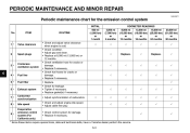
PERIODIC MAINTENANCE AND MINOR REPAIR EAU00471 Periodic maintenance chart for damage. • Replace if necessary. 2 Spark plugs √ Replace. √ Replace. √ 3 * Crankcase ventilation system √ √ √ √ √ 6 4 * 5 * 6 * 7 * 8 * Fuel line Fuel filter Exhaust system Carburetor synchronization Idle speed Evaporative emission control system (For California only) √ √ √ √ √ √ √ √ √ √ √ √ √ √ √ √ √ √ 9 * √...
PERIODIC MAINTENANCE AND MINOR REPAIR EAU00471 Periodic maintenance chart for damage. • Replace if necessary. 2 Spark plugs √ Replace. √ Replace. √ 3 * Crankcase ventilation system √ √ √ √ √ 6 4 * 5 * 6 * 7 * 8 * Fuel line Fuel filter Exhaust system Carburetor synchronization Idle speed Evaporative emission control system (For California only) √ √ √ √ √ √ √ √ √ √ √ √ √ √ √ √ √ √ 9 * √...

Owners Manual
Page 76
... nut EAU00713 Adjusting the rear brake light switch The rear brake light switch, which is activated by the brake pedal, is properly adjusted when the brake light comes on earlier, turn the adjusting nut at the brake pedal end. Periodically check the brake pedal free play , turn the adjusting nut in direction b. 6-24 6 To make the brake light come on just before braking takes effect. PERIODIC MAINTENANCE AND MINOR REPAIR 1. Rear brake light switch 2.
... nut EAU00713 Adjusting the rear brake light switch The rear brake light switch, which is activated by the brake pedal, is properly adjusted when the brake light comes on earlier, turn the adjusting nut at the brake pedal end. Periodically check the brake pedal free play , turn the adjusting nut in direction b. 6-24 6 To make the brake light come on just before braking takes effect. PERIODIC MAINTENANCE AND MINOR REPAIR 1. Rear brake light switch 2.

Owners Manual
Page 85
..., replace it as follows. 1. PERIODIC MAINTENANCE AND MINOR REPAIR EC000103 CAUTION: Do not use a fuse of the specified amperage. 1. 2. 3. 4. 5. Turn the key to "ON" and turn off the electrical circuit in question to the electrical system and possibly a fire. _ _ 1. If the fuse immediately blows again, have a Yamaha dealer check the electrical system. 30 A 15 A 10 A 10 A 15 A Specified fuses: Main fuse: Headlight fuse: Signaling system fuse: Ignition fuse: Carburetor heater fuse: 6-33 Turn the key...
..., replace it as follows. 1. PERIODIC MAINTENANCE AND MINOR REPAIR EC000103 CAUTION: Do not use a fuse of the specified amperage. 1. 2. 3. 4. 5. Turn the key to "ON" and turn off the electrical circuit in question to the electrical system and possibly a fire. _ _ 1. If the fuse immediately blows again, have a Yamaha dealer check the electrical system. 30 A 15 A 10 A 10 A 15 A Specified fuses: Main fuse: Headlight fuse: Signaling system fuse: Ignition fuse: Carburetor heater fuse: 6-33 Turn the key...

Owners Manual
Page 91
... an assembly: wheel, wheel axle, final gear case, and drive shaft. Install the rear wheel, wheel axle, final gear case, and drive shaft by pushing the wheel forward and guiding the drive shaft into the middle gear universal joint. 2. Install the final gear case bolts. 6-39 Install the brake torque rod bolt at the brake shoe plate. 5. Lower the rear wheel so that secure the final gear case to the procedure on the ground. 7. Tighten the axle nut...
... an assembly: wheel, wheel axle, final gear case, and drive shaft. Install the rear wheel, wheel axle, final gear case, and drive shaft by pushing the wheel forward and guiding the drive shaft into the middle gear universal joint. 2. Install the final gear case bolts. 6-39 Install the brake torque rod bolt at the brake shoe plate. 5. Lower the rear wheel so that secure the final gear case to the procedure on the ground. 7. Tighten the axle nut...

Owners Manual
Page 105
SPECIFICATIONS Bulb voltage, wattage × quantity Headlight Tail/brake light Front turn signal/ position light Rear turn signal light Meter lighting Neutral indicator light High beam indicator light Turn signal indicator light Engine trouble warning light Fuses Main fuse Ignition fuse Signaling system fuse Headlight fuse Carburetor heater fuse 30 A 10 A 10 A 15 A 15 A 12 V, 60/55 W × 1 12 V, 8/27 W × 1 12 V, 27/8 W × 2 12 V, 27 W × 2 12 V, 1.7 W × 1 12 V, 1.7 W × 1 12 V, 1.7 W × 1 12 V, 1.7 W × 1 12 V, 1.7 W × 1 8 8-5
SPECIFICATIONS Bulb voltage, wattage × quantity Headlight Tail/brake light Front turn signal/ position light Rear turn signal light Meter lighting Neutral indicator light High beam indicator light Turn signal indicator light Engine trouble warning light Fuses Main fuse Ignition fuse Signaling system fuse Headlight fuse Carburetor heater fuse 30 A 10 A 10 A 15 A 15 A 12 V, 60/55 W × 1 12 V, 8/27 W × 1 12 V, 27/8 W × 2 12 V, 27 W × 2 12 V, 1.7 W × 1 12 V, 1.7 W × 1 12 V, 1.7 W × 1 12 V, 1.7 W × 1 12 V, 1.7 W × 1 8 8-5

Owners Manual
Page 117
...22 Brake light switch (rear), adjusting ...6-24 Brake pads and shoes, checking ...6-25 Brake pedal...3-5 Brake pedal position and free play, adjusting ...6-23 F Final gear oil...6-14 Front fork, checking ...6-29 Fuel ...3-7 Fuel cock...3-8 Fuel tank cap...3-6 Fuses, replacing ...6-33 N Neutral indicator light ...3-2 Noise regulation ...9-4 P Panels, removing and installing...6-7 Parking...5-6 Part locations ...2-1 Pre-operation check list...4-1 H Handlebar switches ...3-3 Headlight bulb, replacing ...6-34 Helmet holder ...3-12 High beam indicator light ...3-2 Horn switch ...3-3 S Safety...
...22 Brake light switch (rear), adjusting ...6-24 Brake pads and shoes, checking ...6-25 Brake pedal...3-5 Brake pedal position and free play, adjusting ...6-23 F Final gear oil...6-14 Front fork, checking ...6-29 Fuel ...3-7 Fuel cock...3-8 Fuel tank cap...3-6 Fuses, replacing ...6-33 N Neutral indicator light ...3-2 Noise regulation ...9-4 P Panels, removing and installing...6-7 Parking...5-6 Part locations ...2-1 Pre-operation check list...4-1 H Handlebar switches ...3-3 Headlight bulb, replacing ...6-34 Helmet holder ...3-12 High beam indicator light ...3-2 Horn switch ...3-3 S Safety...

Owners Manual
Page 118
...36 V Valve clearance, adjusting ...6-17 Vehicle identification number...9-1 W Warranty, extended...9-9 Warranty limited ...9-7 Wheel bearings, checking ...6-31 Wheel (front) ...6-37 Installing ...6-37 Removing ...6-37 Wheel (rear) ...6-38 Installing ...6-39 Removing ...6-38 Wheels...6-19 T Throttle cable free play, adjusting ...6-17 Throttle grip and cable, checking and lubricating...6-27 Tires ...6-17 Tool kit...6-1 Troubleshooting...6-40 Troubleshooting chart...6-41 Turn signal indicator light ...3-2 Turn signal light or tail/brake light bulb, replacing ...6-35 Turn signal switch...3-3
...36 V Valve clearance, adjusting ...6-17 Vehicle identification number...9-1 W Warranty, extended...9-9 Warranty limited ...9-7 Wheel bearings, checking ...6-31 Wheel (front) ...6-37 Installing ...6-37 Removing ...6-37 Wheel (rear) ...6-38 Installing ...6-39 Removing ...6-38 Wheels...6-19 T Throttle cable free play, adjusting ...6-17 Throttle grip and cable, checking and lubricating...6-27 Tires ...6-17 Tool kit...6-1 Troubleshooting...6-40 Troubleshooting chart...6-41 Turn signal indicator light ...3-2 Turn signal light or tail/brake light bulb, replacing ...6-35 Turn signal switch...3-3