

Owners Manual
Page 34
... vehicle is left unattended, always place the transmission in PARK and lock the parking brake. Whenever the ATV is moving could cause transmission damage. Belt Life To extend belt life, use low forward gear when pulling a heavy load at less than seven miles per hour for extended periods and when operating uphill at a slow speed. 32 H: High Gear L: Low Gear N: Neutral R: Reverse P: Park To shift gears, brake to the desired gear. FEATURES AND CONTROLS Automatic Transmission Gear...
... vehicle is left unattended, always place the transmission in PARK and lock the parking brake. Whenever the ATV is moving could cause transmission damage. Belt Life To extend belt life, use low forward gear when pulling a heavy load at less than seven miles per hour for extended periods and when operating uphill at a slow speed. 32 H: High Gear L: Low Gear N: Neutral R: Reverse P: Park To shift gears, brake to the desired gear. FEATURES AND CONTROLS Automatic Transmission Gear...
Owners Manual
Page 35
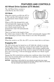
... vehicle automatically engages 4X4 when operating in reverse if the switch is set to the length of time the vehicle may be visible. 4X4 When in 4X4, the demand drive unit Switch will not enable 4X4 until the 4X4 switch is below 3100. Once enabled, 4X4 remains enabled until the engine RPM is turned off. FEATURES AND CONTROLS All Wheel Drive System (ETX Model) The All Wheel Drive system...
... vehicle automatically engages 4X4 when operating in reverse if the switch is set to the length of time the vehicle may be visible. 4X4 When in 4X4, the demand drive unit Switch will not enable 4X4 until the 4X4 switch is below 3100. Once enabled, 4X4 remains enabled until the engine RPM is turned off. FEATURES AND CONTROLS All Wheel Drive System (ETX Model) The All Wheel Drive system...
Owners Manual
Page 37
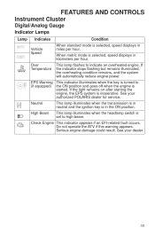
... will automatically reduce engine power. This lamp flashes to (if equipped) the ON position and goes off when the engine is started. Do not operate the ATV if this warning appears. This lamp illuminates when the headlamp switch is inoperative. FEATURES AND CONTROLS Instrument Cluster Digital/Analog Gauge Indicator Lamps Lamp Indicates Vehicle Speed Over Temperature Condition When standard mode is selected, speed displays in miles per...
... will automatically reduce engine power. This lamp flashes to (if equipped) the ON position and goes off when the engine is started. Do not operate the ATV if this warning appears. This lamp illuminates when the headlamp switch is inoperative. FEATURES AND CONTROLS Instrument Cluster Digital/Analog Gauge Indicator Lamps Lamp Indicates Vehicle Speed Over Temperature Condition When standard mode is selected, speed displays in miles per...
Owners Manual
Page 39
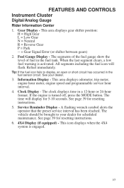
...: H = High Gear L = Low Gear N = Neutral R = Reverse Gear P = Park -- = Gear Signal Error (or shifter between gears) 2. When the last segment clears, a low fuel warning is turned off, press the MODE button. The time will flash. The vehicle should be brought to display, an open or short circuit has occurred in the fuel sensor circuit. Clock Display - If the engine is activated. FEATURES AND CONTROLS Instrument Cluster Digital/Analog Gauge Rider Information Center 1. Tip...
...: H = High Gear L = Low Gear N = Neutral R = Reverse Gear P = Park -- = Gear Signal Error (or shifter between gears) 2. When the last segment clears, a low fuel warning is turned off, press the MODE button. The time will flash. The vehicle should be brought to display, an open or short circuit has occurred in the fuel sensor circuit. Clock Display - If the engine is activated. FEATURES AND CONTROLS Instrument Cluster Digital/Analog Gauge Rider Information Center 1. Tip...

Owners Manual
Page 45
... 523 523 523 651 651 1268 1268 1347 1347 1071 1071 520193 520193 1321 520207 168 168 520194 520194 520194 520194 520203 FMI 3 4 3 4 16 0 3 4 3 4 8 4 3 2 5 3 5 3 5 3 5 3 5 11 3 3 3 4 3 4 2 7 3 Intake Air Temperature Sensor Manifold Absolute Pressure Sensor Crankshaft Position Sensor Gear Sensor Signal Injector 1 (MAG) Ignition Coil Primary Driver 1 (MAG) Fuel Pump Driver Circuit Fan Relay Driver Circuit Idle Air Control Starter Enable Circuit All Wheel Drive Control System Power Throttle Safety Signal Active Descent Control System *Assumes unipolar configuration of stepper motor 43
... 523 523 523 651 651 1268 1268 1347 1347 1071 1071 520193 520193 1321 520207 168 168 520194 520194 520194 520194 520203 FMI 3 4 3 4 16 0 3 4 3 4 8 4 3 2 5 3 5 3 5 3 5 3 5 11 3 3 3 4 3 4 2 7 3 Intake Air Temperature Sensor Manifold Absolute Pressure Sensor Crankshaft Position Sensor Gear Sensor Signal Injector 1 (MAG) Ignition Coil Primary Driver 1 (MAG) Fuel Pump Driver Circuit Fan Relay Driver Circuit Idle Air Control Starter Enable Circuit All Wheel Drive Control System Power Throttle Safety Signal Active Descent Control System *Assumes unipolar configuration of stepper motor 43

Owners Manual
Page 47
... and add marks. 3. See page 48. 6. Pull only light loads. OPERATION Break-In Period Engine and Drivetrain Break-in period. Fill the fuel tank with vehicle operation and handling. 4. Change both the oil and the filter at sustained idle. 5. If a belt fails, always clean away all gearcases after the first 25 hours of the clutches and drive belt will ensure a longer life and better...
... and add marks. 3. See page 48. 6. Pull only light loads. OPERATION Break-In Period Engine and Drivetrain Break-in period. Fill the fuel tank with vehicle operation and handling. 4. Change both the oil and the filter at sustained idle. 5. If a belt fails, always clean away all gearcases after the first 25 hours of the clutches and drive belt will ensure a longer life and better...
Owners Manual
Page 62
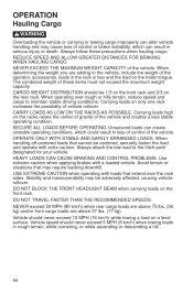
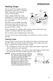
... brakes with loads that extend over rough or hilly terrain, reduce speed and cargo to the hitch point designated for your vehicle. OPERATION Hauling Cargo WARNING Overloading the vehicle or carrying or towing cargo improperly can result in serious injury or death. Always attach the tow load to maintain stable driving conditions. Always follow these items must not exceed the maximum weight capacity...
... brakes with loads that extend over rough or hilly terrain, reduce speed and cargo to the hitch point designated for your vehicle. OPERATION Hauling Cargo WARNING Overloading the vehicle or carrying or towing cargo improperly can result in serious injury or death. Always attach the tow load to maintain stable driving conditions. Always follow these items must not exceed the maximum weight capacity...
Owners Manual
Page 63
... maximum weight capacity of this manual. 1/3 Cargo weight should be evenly distributed (1/3 on the front rack and 2/3 on the rear rack) and mounted as low as possible. NOTICE: Using an improper hitch or exceeding the maximum tongue weight capacity can result in the specifications 2/3 section of the vehicle. Maximum 4" (10 cm) 61 When operating over rough or hilly terrain, reduce speed and cargo weight to extend belt...
... maximum weight capacity of this manual. 1/3 Cargo weight should be evenly distributed (1/3 on the front rack and 2/3 on the rear rack) and mounted as low as possible. NOTICE: Using an improper hitch or exceeding the maximum tongue weight capacity can result in the specifications 2/3 section of the vehicle. Maximum 4" (10 cm) 61 When operating over rough or hilly terrain, reduce speed and cargo weight to extend belt...

Owners Manual
Page 81
... key to water, mud, etc. 1000 (1600) Inspect; replace as needed Inspect periodically; replace as needed 2000 (3200) Change every two years 3000 (4800) Clean out Replace coolant Adjust as needed Remarks ► Radiator (if applicable) ► Cooling hoses (if applicable) ► Engine mounts Exhaust muffler/ pipe D Spark plug E ► Wiring 100 H 100 H 100 H 100 H 100 H 100 H 12 M 12 M 12 M 12 M 12 M 12 M D Clutches (drive and driven) D Front wheel bearings D Brake fluid Spark arrester ► Coolant Idle speed...
... key to water, mud, etc. 1000 (1600) Inspect; replace as needed Inspect periodically; replace as needed 2000 (3200) Change every two years 3000 (4800) Clean out Replace coolant Adjust as needed Remarks ► Radiator (if applicable) ► Cooling hoses (if applicable) ► Engine mounts Exhaust muffler/ pipe D Spark plug E ► Wiring 100 H 100 H 100 H 100 H 100 H 100 H 12 M 12 M 12 M 12 M 12 M 12 M D Clutches (drive and driven) D Front wheel bearings D Brake fluid Spark arrester ► Coolant Idle speed...
Owners Manual
Page 97
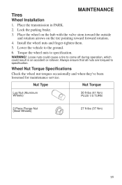
... maintenance service. Install the wheel nuts and finger-tighten them. 5. Place the wheel on the hub with the valve stem toward the outside and rotation arrows on the tire pointing toward forward rotation. 4. Nut Type Lug Nut (Aluminum Wheels) Nut Torque 30 ft-lbs (41 Nm) PLUS 1/4 TURN 2-Piece Flange Nut (Steel Wheels) 27 ft-lbs (37 Nm) 95 WARNING! Lower the vehicle...
... maintenance service. Install the wheel nuts and finger-tighten them. 5. Place the wheel on the hub with the valve stem toward the outside and rotation arrows on the tire pointing toward forward rotation. 4. Nut Type Lug Nut (Aluminum Wheels) Nut Torque 30 ft-lbs (41 Nm) PLUS 1/4 TURN 2-Piece Flange Nut (Steel Wheels) 27 ft-lbs (37 Nm) 95 WARNING! Lower the vehicle...
Owners Manual
Page 100
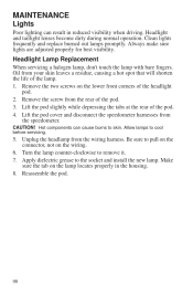
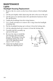
...Oil from the speedometer. Apply dielectric grease to remove it. 7. Clean lights frequently and replace burned out lamps promptly. Headlight Lamp Replacement When servicing a halogen lamp, don't touch the lamp with bare fingers. Lift the pod cover and disconnect the speedometer harnesses from your skin leaves a residue, causing a hot spot that will shorten the life of the headlight... headlamp from the rear of the pod. 4. Lift the pod slightly while depressing the tabs at the rear of the pod. 3. MAINTENANCE Lights Poor lighting can cause burns to cool before servicing. 5. CAUTION!...
...Oil from the speedometer. Apply dielectric grease to remove it. 7. Clean lights frequently and replace burned out lamps promptly. Headlight Lamp Replacement When servicing a halogen lamp, don't touch the lamp with bare fingers. Lift the pod cover and disconnect the speedometer harnesses from your skin leaves a residue, causing a hot spot that will shorten the life of the headlight... headlamp from the rear of the pod. 4. Lift the pod slightly while depressing the tabs at the rear of the pod. 3. MAINTENANCE Lights Poor lighting can cause burns to cool before servicing. 5. CAUTION!...
Owners Manual
Page 101
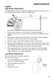
.... Tilt the headlamp upward or downward. 3. Start the engine. Include rider weight on the wall. Loosen the Phillips screw located at the same height. 3. Measure the distance from a wall. Tighten the screw. Position the vehicle on the right side of the headlight pod. Turn the headlight switch to the center of the headlight and make the adjustment. Use the following...
.... Tilt the headlamp upward or downward. 3. Start the engine. Include rider weight on the wall. Loosen the Phillips screw located at the same height. 3. Measure the distance from a wall. Tighten the screw. Position the vehicle on the right side of the headlight pod. Turn the headlight switch to the center of the headlight and make the adjustment. Use the following...
Owners Manual
Page 102
... 5 1/8" turning the adjusting knob. (13 cm) 100 Carefully pull the assembly up to remove it from the headlight mounting tabs. 6. Lift the pod cover and disconnect the speedometer harnesses from the wiring harness. 5. Use a small screwdriver to the end of the pod. 3. Reverse the steps to release it from the headlamp parting line to remove the o-rings from the locking tabs...
... 5 1/8" turning the adjusting knob. (13 cm) 100 Carefully pull the assembly up to remove it from the headlight mounting tabs. 6. Lift the pod cover and disconnect the speedometer harnesses from the wiring harness. 5. Use a small screwdriver to the end of the pod. 3. Reverse the steps to release it from the headlamp parting line to remove the o-rings from the locking tabs...
Owners Manual
Page 103
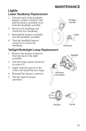
... headlight assembly. 4. Turn the back of the headlight harness counter-clockwise and pull the harness assembly away from the back of the light assembly. 2. Test the light for proper operation. Turn the lamp counter-clockwise to secure the headlamp. Turn the headlight harness clockwise to remove it. 3. Apply dielectric grease to the socket and install the new lamp. 4. Remove the harness connector from the headlight assembly. 2. MAINTENANCE Lights Lower Headlamp Replacement...
... headlight assembly. 4. Turn the back of the headlight harness counter-clockwise and pull the harness assembly away from the back of the light assembly. 2. Test the light for proper operation. Turn the lamp counter-clockwise to secure the headlamp. Turn the headlight harness clockwise to remove it. 3. Apply dielectric grease to the socket and install the new lamp. 4. Remove the harness connector from the headlight assembly. 2. MAINTENANCE Lights Lower Headlamp Replacement...

Owners Manual
Page 120
Grease all zerk fittings immediately after washing. Polishing the Vehicle POLARIS recommends the use clean cloths and pads for polishing the finish on the container. Replacement safety labels are provided by POLARIS at the following items: • Wheel bearings • Radiator • Transmission seals • Brakes • Cab and body panels • Electrical components • Switches and controls • Labels If an informational or graphic label becomes illegible...
Grease all zerk fittings immediately after washing. Polishing the Vehicle POLARIS recommends the use clean cloths and pads for polishing the finish on the container. Replacement safety labels are provided by POLARIS at the following items: • Wheel bearings • Radiator • Transmission seals • Brakes • Cab and body panels • Electrical components • Switches and controls • Labels If an informational or graphic label becomes illegible...

Owners Manual
Page 123
... of fresh oil. 5. Oil will be completely drained of the spark plug cap and reinstall the caps onto the plugs. 4. Turn the engine over several times using electric start. After stabilizing the fuel, remove the spark plugs and add 2-3 tablespoons of oil. 2. Torque to the inside of gasoline. 121 MAINTENANCE Cleaning and Storage Storage Tips Fluid Levels Inspect the fluid levels. If POLARIS fuel system additive is not used, the fuel tank, fuel lines...
... of fresh oil. 5. Oil will be completely drained of the spark plug cap and reinstall the caps onto the plugs. 4. Turn the engine over several times using electric start. After stabilizing the fuel, remove the spark plugs and add 2-3 tablespoons of oil. 2. Torque to the inside of gasoline. 121 MAINTENANCE Cleaning and Storage Storage Tips Fluid Levels Inspect the fluid levels. If POLARIS fuel system additive is not used, the fuel tank, fuel lines...

Owners Manual
Page 130
SPECIFICATIONS SPORTSMAN ETX / HAWKEYE 325 2X4 Maximum Weight Capacity Dry Weight Fuel Capacity Engine Oil Capacity Transmission Oil Capacity Demand Drive Fluid Capacity Coolant Capacity Front Rack/Box Capacity Rear Rack/Box Capacity Receiver Hitch Tongue Capacity Hitch Towing Rating Unbraked Trailer Towing Capacity* Overall Length/Width/Height Wheelbase Ground Clearance Minimum Turning Radius Engine Displacement Bore x Stroke Alternator Output Compression Ratio Starting System Fuel System Ignition System Spark Plug / Gap Lubrication System Driving System Type Front Suspension Rear Suspension ...
SPECIFICATIONS SPORTSMAN ETX / HAWKEYE 325 2X4 Maximum Weight Capacity Dry Weight Fuel Capacity Engine Oil Capacity Transmission Oil Capacity Demand Drive Fluid Capacity Coolant Capacity Front Rack/Box Capacity Rear Rack/Box Capacity Receiver Hitch Tongue Capacity Hitch Towing Rating Unbraked Trailer Towing Capacity* Overall Length/Width/Height Wheelbase Ground Clearance Minimum Turning Radius Engine Displacement Bore x Stroke Alternator Output Compression Ratio Starting System Fuel System Ignition System Spark Plug / Gap Lubrication System Driving System Type Front Suspension Rear Suspension ...
Owners Manual
Page 135
... to continue your vehicle. This policy does not apply to products that you receive safety information and notices regarding your warranty coverage. however, you should warranty register your product at a local POLARIS dealer in which the product was purchased: If you are traveling within the country where your product was purchased, Warranty and Service Bulletin repairs may use...
... to continue your vehicle. This policy does not apply to products that you receive safety information and notices regarding your warranty coverage. however, you should warranty register your product at a local POLARIS dealer in which the product was purchased: If you are traveling within the country where your product was purchased, Warranty and Service Bulletin repairs may use...

Owners Manual
Page 137
... off road vehicles 100cc or greater emissions-certified vehicles starts on the vehicle as the standard factory warranty that would cause it is first purchased, this warranty is extended for at least as long as a whole. Environmental Protection Agency emission regulations. warrants that at the time it to fail to the following systems: • Air-induction system • Fuel system • Ignition system • Exhaust gas...
... off road vehicles 100cc or greater emissions-certified vehicles starts on the vehicle as the standard factory warranty that would cause it is first purchased, this warranty is extended for at least as long as a whole. Environmental Protection Agency emission regulations. warrants that at the time it to fail to the following systems: • Air-induction system • Fuel system • Ignition system • Exhaust gas...

Owners Manual
Page 144
INDEX F Foot Brake, Auxiliary ...Footwell Removal ...Fuel Recommendations ...Fuel Safety ...Fuel Tank Cap ...Fuse Replacement ...30 93 31 11 31 97 M Maintenance Chart...76-79 Master Cylinder ...28 Metric Display ...38 Mode Switch ...24 Modifications...9 G Gasoline Handling ...11 Gauge, Code Definitions ...42-43 Gauge, Digital/Analog...34-41 Gear Selector ...32 Gloves ...9 N Noise Emission Control System ...75 O Oil Engine ...81-84 Transmission...85-86 Oil and Filter Change ...83-84 Oil Change, Transmission ...86 Oil Level Engine ...82 Transmission...86 Oil Recommendations ...81...
INDEX F Foot Brake, Auxiliary ...Footwell Removal ...Fuel Recommendations ...Fuel Safety ...Fuel Tank Cap ...Fuse Replacement ...30 93 31 11 31 97 M Maintenance Chart...76-79 Master Cylinder ...28 Metric Display ...38 Mode Switch ...24 Modifications...9 G Gasoline Handling ...11 Gauge, Code Definitions ...42-43 Gauge, Digital/Analog...34-41 Gear Selector ...32 Gloves ...9 N Noise Emission Control System ...75 O Oil Engine ...81-84 Transmission...85-86 Oil and Filter Change ...83-84 Oil Change, Transmission ...86 Oil Level Engine ...82 Transmission...86 Oil Recommendations ...81...

