Sony STR-K700 Support Question
Sony STR-K700 Support Question
Find answers below for this question about Sony STR-K700 - Fm Stereo/fm-am Receiver.Need a Sony STR-K700 manual? We have 5 online manuals for this item!
Question posted by tstelagogas on October 28th, 2014
Is Sony Str-k700 Compatible With Ps3
The person who posted this question about this Sony product did not include a detailed explanation. Please use the "Request More Information" button to the right if more details would help you to answer this question.
Current Answers


Related Sony STR-K700 Manual Pages
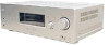
Marketing Specifications (HTDDW700 Home Theater System) - Page 2
...; www.sony.com
Last Updated: 04/04/2006 All rights reserved. All other are registered trademarks of Sony. Nonmetric weights...Component Home Theater System
Specifications
Receiver
Audio Audio Power Output: 800W (133w x 5 + 135w
(1KHz, 10% THD))
Inputs and Outputs Analog Audio Input(s): 4 (Rear) Antenna Terminal(s): Yes (FM 75ohms, AM
Loop) Coaxial Audio Digital Input(s): 1 (Rear) Optical Audio...
Service Manual - Page 1
.... FM STEREO FM-AM RECEIVER
9-887-073-01
2006A1678-1 © 2006.01
Sony Corporation
Home Audio Division Published by Sony Techno Create Corporation "DTS" and "DTS Digital Surround" are trademarks of area code US only) With 6 ohm loads, both channels driven, from 250 milliwatts to rated output. SERVICE MANUAL
Ver. 1.0 2006.01
STR-K700
US Model Canadian Model
• STR-K700...
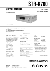
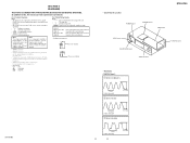
Service Manual - Page 2
... longer time. About area codes
The area code of the receiver you purchased is more viscou-s (sticky, less prone to...example, "Models of area code AA only". Rear Panel - STR-K700
General Power requirements 120 V AC, 60 Hz
Power consumption Area....
2
Notes on chip component replacement • Never reuse a disconnected chip component. • Notice that the minus side of a tantalum...
Service Manual - Page 3
...36
Earth Ground
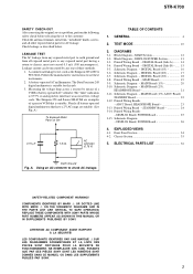
Fig. REPLACE THESE COMPONENTS WITH SONY PARTS WHOSE PART NUMBERS APPEAR AS SHOWN IN THIS MANUAL OR IN SUPPLEMENTS PUBLISHED BY SONY. ATTENTION AU COMPOSANT AYANT RAPPORT À... 35
5. Using an AC voltmeter to use these instruments.
2. SAFETY-RELATED COMPONENT WARNING!! STR-K700
SAFETY CHECK-OUT After correcting the original service problem, perform the following safety check...
Service Manual - Page 4
STR-K700
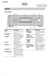
Receiver
Front panel
1 234
?/1
SECTION 1 GENERAL
5
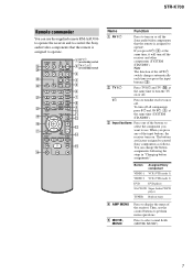
This section is extracted from remote commander.
Press to select the input mode when the same components are connected to turn the receiver on the display. Receives...Timer function and the duration which the receiver turns off .
Press to playback. Press...The current status of the selected component or a list of all speakers at ...
Service Manual - Page 5
...qa
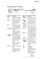
MEMORY D.RANGE STEREO MONO
0
9
...indicator does not light up when audio signal is set to the ...receiver downmixes the source sound.
Lights up when the receiver applies Pro Logic processing to tune in radio stations you have preset. The boxes around the letters vary to output the center and surround channel signals. STR-K700.... Lights up when the receiver is activated. Lights up when...
Service Manual - Page 6
STR-K700
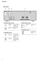
Rear panel
1
23
4
DIGITAL OPTICAL
VIDEO 2 IN
DVD IN COAXIAL
ANTENNA
AM
L L
R R
AUDIO IN AUDIO IN AUDIO IN
S
DVD VIDEO 2
L
R AUDIO IN VIDEO 1
RL
RL
+
++
+
SUB WOOFER
RL SURROUND
SPEAKERS
CENTER
RL FRONT
A DIGITAL INPUT section
OPTICAL Connects to a CD
White (L) jack
player, etc. B ANTENNA section
FM ANTENNA
AM ANTENNA
Connects to the FM wire antenna supplied...
Service Manual - Page 7
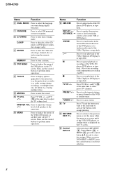
... control Sony components as follows. C Input buttons Press one of the input buttons, the receiver turns on /standby) switch
3
4 5
DUAL MONO
123
6
FM MODE
456
7
7
>10/
-
MOVIE MUSIC
1 AV ?/1
(on/standby) switch
2 TV ?/1, ?/1
(on . Note The function of the receiver.
The buttons are factory assigned to perform menu operations. wg wf wd ws
wa w; STR-K700
Remote...
Service Manual - Page 8
...same time. STR-K700
Name
Function
... enter direct tuning mode. audio settings during digital broadcast.
...stereo reception. Press TV VOL +/- TUNING +/-
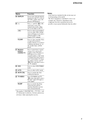
G FM MODE
Press to scan a station.
Press to fastforward/rewind of the VCR, CD player, DVD player, or tape deck.
Press TV CH +/-
level of all speakers at the same time to activate the buttons with components...
Service Manual - Page 9
... return to select 2CH STEREO mode. V 2CH
Press to continuous playback, etc. SLEEP
Press to select
the input signal (TV input or
video input). STR-K700
Name
Function
S DISPLAY
Press... differently than described.
9 Therefore, depending on the component, the above explanation is intended to serve as references when operating the receiver. Press -/--
Press 0/10 to select the TV...
Service Manual - Page 10
STR-K700
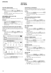
SECTION 2 TEST MODE
FACTORY PRESET MODE All preset contents are not counted again.
3. Procedure:
1. ... DIGITALEXD PRO LOGIC II x DTS-ES NEO:6 MPEG-2 AAC RDS MEMORY SP B SLEEP OPT COAX MULTI CH IN 96/24 D.RANGE EQ STEREO MONO DIRECT
dB kHz mft.
SOFTWARE VERSION DISPLAY MODE The software version is performed. Procedure:
1. While depressing the A.F.D. KEY CHECK MODE Button check...
Service Manual - Page 11
..., 20 ns/DIV
3 IC1301 ws (XIN)
4.2 Vp-p
STR-K700
81 ns 1 V/DIV, 40 ns/DIV
11
11
4.4 Vp-p For Printed Wiring Boards.
Note: The components identified by mark 0 or dotted line with mark 0 are taken with a oscilloscope. • Circled numbers refer to ground un-
No mark : FM • Voltages are critical for electrolytics and...
Service Manual - Page 13
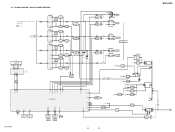
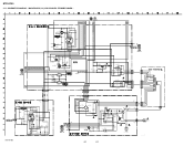
... REG
IC1001
3
+5V REG
1
RELAY +B
AUDIO +7V
AUDIO -7V
TUNER +10V
IC821
1
+7V REG
3
IC822
3
-7V REG
2
IC1902
3
+10V REG
1
+3.3V(STBY)
IC1111 1 RESET 2
Q911 AC DET
IC1904
3
+3.3V REG
1
R803 D920-923
F1 F2
D910-913
T902
D914
Q901 RELAY DRIVE
D915 RY901
STR-K700
13
13
STR-K700
AC IN BLOCK DIAGRAM -
3-2. DISPLAY/POWER...
Service Manual - Page 14
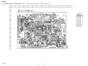
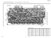
...D1001 D1301 D1302
Location
B-5 C-2 C-2
IC1101 D-5 IC1111 C-6 IC1131 E-5 IC1301 B-2 IC1303 C-2 IC1401 E-2 IC1452 D-3 IC1501 D-4 IC1502 B-4 IC1503 D-4
STR-K700
14
14 DIGITAL BOARD (SIDE A) - • See page 11 for Circuit Boards Location.
:Uses unleaded solder.
1
2
3
4
5
6
...48 1
13 12
IC1401
E
IC1131
• Semiconductor Location
Ref.
PRINTED WIRING BOARD - STR-K700
3-3. No.
Service Manual - Page 15
...) TN1
D E CNP801
(Page 24)
TUNER UNIT
B
IC1031 IC1902
1
2
5
5
3
1
6
IC1901
8
C
IC1904
1
4
D
A MAIN
BOARD
CNP503
(Page 19)
5
B 1
MAIN
BOARD
E
CNP503
(Page 19)
C
DISPLAY
BOARD
CNS100
F
(Page 25)
STR-K700
F MAIN BOARD CNP502 (Page 19)
IC1001
G MAIN BOARD CNP501 (Page 19)
15
15...
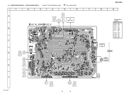
Service Manual - Page 19
... - MAIN BOARD - • See page 11 for Circuit Boards Location.
:Uses unleaded solder.
STR-K700
1
2
3
4
5
6
7
8
9
10
11
12
13
14
15
16
ADCC BOARD
A
CNP2000
(Page 23)
AUDIO IN
SA-CD/CD
DVD
VIDEO 2
H
VIDEO 1 AUDIO IN
R
L
R
L
R
L
R
L
B
SUB WOOFER
-+
SPEAKER IMPEDANCE USE 6-16 Ω
SURROUND
R
-+
L
-+
CENTER
-+
FRONT
R
-+
L
-+
C
D
G
DIGITAL BOARD...
Service Manual - Page 22
...0.033
C2013 1
50V
D2014 ISS133T-72
D2013 ISS133T-72
C2014 0.47 50V
TP2000 CHASSIS GND
R2015 33k
R2016 15k
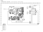
STR-K700
CNP801 5P
CNP906 5P
C915 2200 25V
C916 1000 25V
D920 10EDB40-TA2B5
D921 10EDB40-TA2B5
R810 0.22 D923 10EDB40-...JW
T902 R900 3.3M
G901 EARTH TERMINAL
CNP903 3P CNP904 2P
CNP900 2P
No mark : FM
22
22
MAIN BOARD (3/3), ADCC BOARD, STANDBY BOARD - SCHEMATIC DIAGRAM -
Service Manual - Page 23
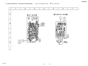
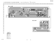
PRINTED WIRING BOARDS - ADCC BOARD, HEADPHONE BOARD - • See page 11 for Circuit Boards Location.
:Uses unleaded solder.
1
2
3
4
5
6
7
A
L MAIN BOARD CN701 (Page 19)
B
AUTO CAL MIC
4
1
IC2000
C
1
H MAIN
BOARD
4
D
CNP732
(Page 19)
PHONES
STR-K700
STR-K700
23
23 3-12.
Service Manual - Page 24
...
3-13. PRINTED WIRING BOARD - D901 D910 D911 D912 D913 D914 D915 D920 D921 D922 D923
Location
D-5 B-6 B-6 B-6 C-6 C-6 C-6 E-4 E-4 E-4 E-4
Q901 C-5 Q911 D-5
STR-K700
2 2
1 1
F901
POWER TRANSFORMER (SUB)
E E
1
5
1
5
J MAIN BOARD CNP916 (Page 19)
D DIGITAL BOARD CNP505 (Page 15)
24
24
7
8
I
MAIN BOARD CNP901 (Page 19)
9
10
T901 POWER TRANSFORMER
(...
Service Manual - Page 25
...D103 D104 D105
Location
B-4 B-2 B-3 B-3 B-7
IC100 A-7 IC101 B-6 IC102 A-9
Q110 C-7
25
25
STR-K700
11
12
13
14
4 1 42
1
7
IC101
14
8
A.F.D. DISPLAY BOARD, POWER BOARD - &#... VOLUME
INPUT MODE
INPUT SELECTOR
DISPLAY
5 1
10
15
IC102
IC100
3
1
F
G
H
STR-K700
• Semiconductor Location
Ref. No. 3-14. MOVIE
MUSIC
DIMMER
SLEEP
2CH
1 4 PRINTED WIRING BOARDS -
Similar Questions

Str-k700 Need To Know How To Change The Station?
want to find out how to navigate the stations and preset the
want to find out how to navigate the stations and preset the
(Posted by javiez1966 2 years ago)

Sony Str K700 With No Remote
How so I change the radio stations on my Sony STR K700 without the remote?
How so I change the radio stations on my Sony STR K700 without the remote?
(Posted by brian7hunter 2 years ago)

What Time S The Best Adapter To Get This Stereo To Receive Bluetooth?
(Posted by Jasworx 3 years ago)

What Is The Code To Program The Remote Control For My Sony Str-k700-fm Receiver
(Posted by rickcharles246 11 years ago)