
Sharp XL-DK255 Support Question
Sharp XL-DK255 Support Question
Find answers below for this question about Sharp XL-DK255.Need a Sharp XL-DK255 manual? We have 1 online manual for this item!
Question posted by Bigchance2 on August 16th, 2014
I Can't Get My Xldk255 To Completely Power Down. It Is Stuck In Stand By Mode
The person who posted this question about this Sharp product did not include a detailed explanation. Please use the "Request More Information" button to the right if more details would help you to answer this question.
Current Answers
Related Sharp XL-DK255 Manual Pages
Service Manual - Page 1
... Circuit 5-1 [2] IC Voltage 5-3
CHAPTER 6. XL-DK225
SERVICE MANUAL
No. ADJUSTMENTS [1] CD Section 2-1 [2] Test Mode 2-2 [3] Standard Specification Of Stereo System
Error ... 2. FLOWCHART [1] Troubleshooting 7-1
CHAPTER 8.
S7734XLDK225/
MICRO COMPONENT SYSTEM
VIDEO /AUX
MODEL XL-DK225
XL-DK225 Micro Component System consisting of XL-DK225 (main unit) and CP-DK225 (speaker system)....
Service Manual - Page 2
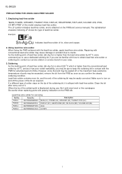
... Clean the bit after every use , file it .
XL-DK225
AXSMEPeRuLardEr-vMkMiiCocePAePt1U1M55T00aIOnuNaSl FOR USING LEAD-FREE SOLDER
1.
Description
PWB-A
92LPWB6895MANS MAIN (A1), POWER (A2), SPEAKER (A3), TRANSIT iPOD (A4)
PWB-B
...-D
92LPWB6894CDUS CD MP3
- 2i However, since the land may be peeled off the power of parts may cause damage or accident due to turn on the tip of time....
Service Manual - Page 3
...XL-DK225
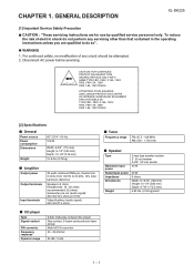
[1] Important Service Safety Precaution
CAUTION : "These servicing instructions are qualified to 20 kHz, 10% total harmonic distortion
Speakers: 6 ohms Headphones: 16 - 50 ohms (recommended: 32 ohms) Subwoofer pre-out (audio signal): 200 mV/10 k ohms at 70 Hz
Video/Auxiliary (audio...6A, 125V FUSES.
[2] Specifications
General
Power source Power consumption Dimensions
Weight
AC 120 V - ...
Service Manual - Page 4
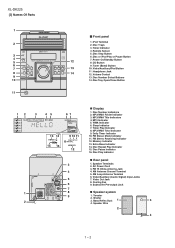
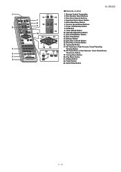
...Power On/Standby Button 8. Video/Auxiliary/iPod Button 11. Headphone Jack 12. WMA Indicator 6. FM Stereo Receiving Indicator 12. Memory Indicator
13. Cooling Fan
6
9. CD Button 9. FM Stereo Mode Indicator 11. Video/Auxiliary (Audio...3. Extra Bass Indicator 14. AC Power Cord
3. Speaker Wire
2
4
1 - 24 Disc Pause Indicator 16. XL-DK225 [3] Names Of Parts
10
...
Service Manual - Page 5
XL-DK225
Remote control
1
1. Equalizer Mode Select Button
8
12
5. Memory Button
14. Disc Play or Pause Button
15.... Up Button
20
21 22
18. Disc Direct Search Buttons
7
4. Disc Clear/Dimmer Button
16
17
12. Play Mode Button
6
21. Power On/Stand-by Button
8. Disc Stop Button
13. Disc Number Select Buttons
13
3. Video/Auxiliary/iPod Button 11. Volume Up and...
Service Manual - Page 6
... switch when TRAY is moving . Can't detect CAM switch when CAM is moving . CD ERROR CODE DESCRIPTION
Error 10* 11* 20*
21*
Explanation CAM error. XL-DK225
CHAPTER 2.
Service Manual - Page 7
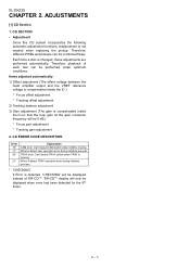
...pick-up location. Laser ON. > key input. CLV Servo ON > key input. STOP and return to enter the test mode.\
XL-DK225
Step 1 Step 2 Step 3 Step 4 Step 5
CD
TE ST
OPEN/CLOSE operation is using manual. > key ...1 Hold down the 3 button and 44 button. [2] Test Mode • Setting the test mode During stand-by mode, press STOP button while pressing down > key for more than 2 sec.
Service Manual - Page 8
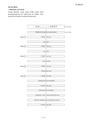
...
= FOFF : XX
f) Tracking Offset
= TOFF : XX
g) RFRP
= RFRP : XX
h) Focus Error
(RW Judgement)
= RW : XX - XXXX
i) Focus Error
(Other than 1 sec, it directly
To cancel: Power OFF
2 - 3
XL-DK225
STOP and return to Step 1
Note
Sliding the PICKUP with , > button can be set / >> for more than RW Judgement) = DA : XX -
Service Manual - Page 9
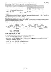
Press the POWER ON/STAND-BY button to stand-by mode.
2. While pressing down the 3 button and the number will be displayed as below. button.
Unplug the AC cord and the unit is detected, 'CHECKING' will ...
Service Manual - Page 10
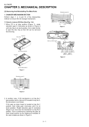
... until disc tray is at tray No.1 play position. In another case, if CD mechanism is at stalk position.
Figure 1
Reduction gear C
Front Rear Figure 2
2. XL-DK255
CHAPTER 3. CHANGER MECHANISM SECTION Perform steps 1, 2, 9 and 10 of the disassembly method to remove the CD changer mechanism.
1.1 How to tray No.3 position. MECHANICAL DESCRIPTION...
Service Manual - Page 11
...C3)x1
PULL
Front Panel
4 Rear Panel with Speaker PWB
1. Knob J1) X 1
5
2. XL-DK255
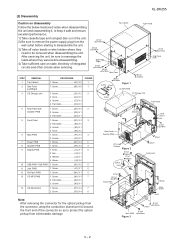
[2] Disassembly
Caution on static electricity of the unit. 2) Be sure to keep it safe and ensure...X 2 3. Socket C3) X 3 4. Socket D2) X 1
3. Flat Cable D3) X 1
5 Front Panel
6 Main PWB 7 Power PWB 8 Speaker PWB 9 Display PWB
1. Flat Cable E2) X 2
3. Socket E3) X 1
4. Hook E4) X 2
1. Screw...
Service Manual - Page 12
...
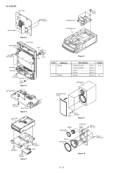
Figure 9
Tweeter Tweeter Ring
Woofer Woofer Ring
Front Board
(B1)x2 Ø3x14mm
(A4)x4 Ø3.5x14mm
Figure 10
3 - 3 Screw A3) X 4 4. Net Frame Ass'y A1) X 1 2. XL-DK255
Rear Panel
(H1)x2 Ø3x10mm
CD Mechanism
(P2)x4 Special
Speaker PWB
Figure 4
Display PWB
Front Panel
(J2)x1
CD Changer Unit
(J4)x6...
Service Manual - Page 23
... SW709 SW710 SW711 SW712 VR701
DESCRIPTION DISC4 DISC5 OPEN/CLOSE DISC1 DISC2 DISC3 POWER ON/STAND-BY PLAY/REPEAT STOP VIDEO/AUX/USB TUNER (BAND) CD VOLUME
POSITION ...is a fuse type.
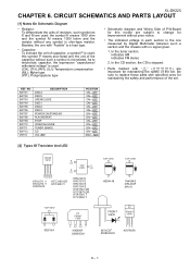
• Capacitor: To indicate the unit of capacitor, a symbol P is microfarad. XL-DK225
CHAPTER 6. CIRCUIT SCHEMATICS AND PARTS LAYOUT
[1] Notes On Schematic Diagram
• Resistor: To differentiate the units...
Service Manual - Page 34
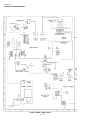
XL-DK225
[4] Charts Of Connecting Wires
WH
F F C 7 0 5
TUNER PACK
9
FFC301
A
ANTENNA
1
FM
GND
... 4 5 6
C N P 8 0 2
7654321
BI701
11 9 7 5 3 1 12 10 8 6 4 2
CNP705
2 4 6 8 10 13579
CNP702
17 15 13 16 14
C
1 2 CNS703
POWER PWB-A2
PT801
G
WH BK
H
AC POWER SUPPLY CORD
AC 120V~60Hz
C N S 8 0 5 C N P 8 0 5
PT841
BI703
1 2 WH RD
VOLUME LED PWB-B4
W H
BI702
987654321
DISPLAY PWB-B1...
Service Manual - Page 40
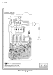
... solder" for instructions and precautions. XL-DK225
POWER PWB-A2
5
4
6
3
7
8
2
9
1
6 54321
T.F.
8 9 10 11 12 13 14 15 16 17
BC E
BK WH
POWER SUPPLY AC 120V~60Hz
BC E
10 9 8 7 6 5 4 3 2 1
1
2
3
6 54 32 1
Lead-free solder indication Lead-free solder is used in the POWER PWB. Figure 6-17: WIRING SIDE OF POWER PWB
6 - 18
COLOR TABLE W H WHITE...
Service Manual - Page 54
... and renting this section does not operate even after the above step is clean. Turn the power off any adjustment make certain that the lens is taken, check the following items.
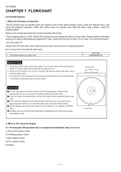
Remove the... cannot be used on car CD players or on the laser pickup lens. FLOWCHART
[1] Troubleshooting
1.
XL-DK225
CHAPTER 7. When the CD does not function
The CD section may be effective for about 20...
Service Manual - Page 56

Yes
A normal jump operation cannot be completed or the
beginning of the track cannot be read. Check the around pin 25 on IC1, ...No "Initialization" is OK. Yes
The tracking servo is not possible. Yes
The spin driver circuit is possible, but play operation.
XL-DK225
(2) Focus-RF system check. Check the TE waveform at pins 15, 16 and 23 on IC1.
Check around pin 23 on...
Service Manual - Page 67
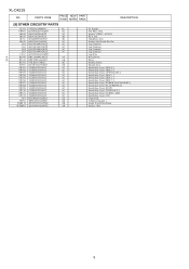
...,Key Type [ OPEN/CLOSE ] Switch,Key Type [ DISC 1 ] Switch,Key Type [ DISC 2 ] Switch,Key Type [ DISC 3 ] Switch,Key Type [ POWER ON/STAND-BY ] Switch,Key Type [ PLAY/REPEAT ] Switch,Key Type [ STOP ] Switch,Key Type [ VIDEO/AUX ] Switch,Key Type [ TUNER / XM ] Switch,...QLUGPA001AWZZ
AC
LG4 QLUGPA001AWZZ
AC
LG5 QLUGPA001AWZZ
AC
LUG1 QCNWNA863AWPZ
! XL-DK225
NO. RL841 RRLYDA002AWZZ
AF
!
Service Manual - Page 70
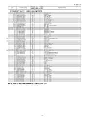
...Rear Panel [For Canada] Side Panel, Left Side Panel, Right Knob, VOLUME Nylon Band Bushing, AC Power Supply Cord Chassis, Main Holder, Fuse Cushion, Leg Chassis, Changer Unit Holder, FL Display Holder, LED...X8mm Screw, M3 X10mm Screw, M3 X6mm
NOTE: FOR CD MECHANISM PARTS, ITEM NO.
ARE 3XX
XL-DK225
12 PARTS CODE
PRICE NEW PART RANK MARK RANK
DESCRIPTION
[10] CABINET PARTS / CD MECHANISM ...
Service Manual - Page 72
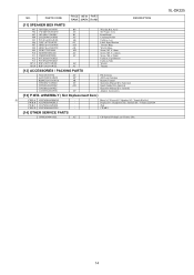
... Antenna Remote Control Operation Manual [For America] Quick Guide [For America] Operation Manual [For Canada] Adaptor Accessories
[13] P.W.B. PWB-A 92LPWB6895MANS
-
PWB-B 92LPWB6894DPLS
- NO.
Main A1 / Power A2 / Speaker A3 / Transit iPod A4 Display B1 / Headphone B2 / Reflash B3 / Volume LED B4 iPod CD MP3
[14] OTHER SERVICE PARTS
UDSKA0004AFZZ
AZ
CD...
Similar Questions

Won't Power Up But Has Flashing Timer Lights.
unit was working until we lost power one night. I have tried multiple outlets with no changes. Unit ...
unit was working until we lost power one night. I have tried multiple outlets with no changes. Unit ...
(Posted by rothellkc 3 years ago)

Delete Individual Or All Preset Stations. Xldk255
How to reset all preset radio stations.....or delete individual presets. Xldk255
How to reset all preset radio stations.....or delete individual presets. Xldk255
(Posted by ldswat 3 years ago)

I Had Power Surge Sharp Xl-dk255 Will Not Power Up.
I had power surge AND MY Sharp XL-DK255 will not power up. None of the mother /power borad have burn...
I had power surge AND MY Sharp XL-DK255 will not power up. None of the mother /power borad have burn...
(Posted by beneathhiswings 4 years ago)

Problem With Unit Shut Down (off).
After a recent brief power failure we had to reset most of electronic epuipmentin the house. The Sha...
After a recent brief power failure we had to reset most of electronic epuipmentin the house. The Sha...
(Posted by hckos 12 years ago)