Sharp LC-26SH12U Support Question
Sharp LC-26SH12U Support Question
Find answers below for this question about Sharp LC-26SH12U - 26" LCD HDTV.Need a Sharp LC-26SH12U manual? We have 1 online manual for this item!
Question posted by amtjeannet on December 22nd, 2012
Location Of Antenna Input On The Menu
I need to check the Input in my TV set, and I can't find it in the Menu.
Current Answers
Related Sharp LC-26SH12U Manual Pages
Service Manual - Page 1

CONTENTS
Page
• SERVICING NOTICES ON CHECKING A1-1 • HOW TO ORDER PARTS ...A1-1 • IMPORTANT ...A1-1 • ABOUT LEAD....
The contents are subject to change without notice. S3701LC26SH12
LCD COLOR TELEVISION
MODEL LC-26SH12U
In the interests of user-safety (Required by safety regulations in some countries) the set should be restored to its original condition and only parts ...
Service Manual - Page 2

...parts which need special ...LCD PANEL
Avoid a shock to keep the indications and notices in this equipment have not the 500V insulation resistance meter, use the insulation material such as a mark, the designated parts must be used .
4. The inside . And be found on the TV. 3. Insulation resistance between the antenna...in your SERVICE MANUAL. Check the insulation between the cord...
Service Manual - Page 4

... TV Sound Tuner Sound Muting Video Signal
LCD Size / Visual Size LCD ...Type Number of Pixels
View Range
Position Size Impedance Max 10%(Typical) Analog Digital System Destination CH Coverage
Picture(FP) Sound(FS) FP-FS
Left/Right Up/Down
Input Level Output Level S/N Ratio (Weighted) Horizontal Resolution at DVD Mode
RGB Signal Audio Signal
Output Level Input Level Output Level
at DVD at TV...
Service Manual - Page 5

...
UM size x pcs
Total Keys
Keys
POWER
FUNCTION
Source POWER
DISPLAY
LIGHT
SEARCH+
SEARCH- SURROUND
MUTE
FREEZE
MENU
LEFT
ENTER
RIGHT
UP
DOWN
EXIT
RETURN
FAVORITE A
FAVORITE B
FAVORITE C
FAVORITE D
FAVORITE
SLEEP
AUDIO
AV MODE...A2-2 CH+
CH-
VIEW MODE
1
2
3
4
5
6
7
8
9
0
ŋ
ENT
INPUT
FLASH BACK
VOL+
VOL-
PLAY
REC
STOP
PAUSE
SKIP+
SKIP-
Service Manual - Page 6
...
Auto Setup(Language/CH Program)
Picture Setting(TV)
AV Mode(Picture Preference)
Brightness , Contrast , Color
Tint
Sharpness
Color Temperature
Cable Clear
Backlight
Picture Setting(PC)
Brightness , Contrast
HOR Position ... Scroll
Cinema Mode
Aspect
PFC(Power Factor circuit)
Freeze frame
PIP/POP
Direct Input Selection
Digital Out
Dolby Digital
MPEG
PCM
DTS
Yes No
Yes Yes
3 -D...
Service Manual - Page 7

...720×576p (4:3)
720×576p (16:9)
1280×720p
1920×1080i
Component Input
720×480i (4:3)
720×480i (16:9)
720×480p (4:3)
720×480p...Antenna
Poles
Terminal
Loop Antenna
Terminal
U/V Mixer
DC Car Cord (Center+)
Guarantee Card
Warning Sheet
Circuit Diagram
Antenna Change Plug
Service Facility List
Important Safeguard
Dew/AHC Caution Sheet
Quick Set...
Service Manual - Page 8

...) Yes Yes
A2-5 Input 3
Other Terminal
Rear
AC Inlet
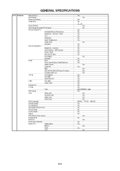
Approx. GENERAL SPECIFICATIONS
G-12 Interface
G-13 Set Size G-14 Weight G-15 Carton G-16 Material G-17 Environment
Switch
Indicator Terminals
Top
Power (Tact)
Channel Up/Menu Up
Channel Down/Menu Down
Volume Up/Menu >
Volume Down/Menu <
Menu
Play
Eject
Skip+, Search+
Skip-, Search- Input 1
Video Input 2
Audio Input 2
S -
Service Manual - Page 10

... the 9 screws 4. 7. Remove the 4 screws 1. 2. Disconnect the following connector: (CP3401).
2. Remove the Digital PCB and Shield Digital in the direction of arrow (B).
1 2 3 2
4 4
Shield Digital
1-7: COVER LCD (Refer to Fig. 1-7)
1. Remove the Power PCB in the direction of arrow.
1 1
1
11 11
1
Power PCB
Fig. 1-6
B1-2 Remove the 4 screws 2. 4. Remove the 8 screws...
Service Manual - Page 11
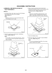
... IC leads using tweezers and remove the IC by moving with the IC desoldering machine. (Refer to Fig. 2-3.)
NOTE
Some ICs on all the parts located within 10 mm distance from any damage. (Refer to Fig. 2-4.) NOTE Do not move back and forth easily after desoldering completely, pickup the corner of...
Service Manual - Page 13

...channel setting, and the POWER ON total hours.
Display of the Adjustment MENU on the screen. DOWN (Minimum)
1
Power ON
VOL. DOWN (Minimum)
6
Standard Time
Operations
2 sec. Can be checked of ...you set factory initialization, the memories are displayed on the screen. To enter to the "WHEN REPLACING EEPROM (MEMORY) IC".
DOWN (Minimum)
9
2 sec. 2 sec. Check of factory TV ...
Service Manual - Page 14
... off the power. 7. Turn on the power.
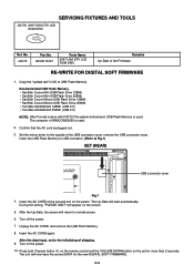
C-2 The Up-Date will return to normal screen. 6. After the data input, set and turn on the power. 10. SERVICING FIXTURES AND TOOLS
JG176 2007 USA DTV LCD ROM DISC
Ref. Insert the USB Flash Memory to USB connector. (Refer to USB Flash Memory. Insert the...
Service Manual - Page 15
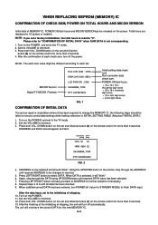
...check sum, turn off the power. Press both VOL. MICON Version Digital TV MICON Fimware
HCS CHK SUM : 07EA HRM CHK SUM : 9BD4 LCD PWR ON : 0000 OEC6088A_T039 DTV CA03B72232
FIG. 1
Initial setting data check sum. Turn on the set... should "blink". Press LEFT/RIGHT button to the initializing of each set to finish DATA input. Press both VOL. When DATA is undertaken where it will turn ...
Service Manual - Page 16

... 22 V POSI 60Hz
NO. Using the remote control, set the brightness and
contrast to select "CONTRAST MAX". 10. Check if the picture is normal. 12. Activate the adjustment mode... tools for TV, VIDEO1, VIDEO2, ColorStream HD, HDMI-0 and PC mode, press the INPUT button on the remote control to set and the
...CENT 24 BAK LIGHT MAX 25 BAK LIGHT MIN 26 BRIGHT CENT 27 BRIGHT MAX 28 BRIGHT MIN 29 ...
Service Manual - Page 17

.... becomes "132". 22. D-2 Playback the DVD(480i) disc. (COMPONENT Input) 10.Press the INPUT button on the remote control to set to select "R DRIVE(N)". 6. Using the remote control, set in Aging Test for more than 15 minutes. 2. Check if the picture is normal. 6. Place the set the brightness and contrast to
the AV mode. 4. Press the...
Service Manual - Page 18

... control to select "CONTRAST CENT". 4. Receive the monoscope pattern. (VIDEO Input) 7. Using the remote control, set to the HDMI mode. 19. Playback the DVD(480i) disc. (HDMI Input) 18. Press the LEFT/RIGHT button on the remote control to select "CONTRAST CENT". 16. Check if the picture is normal. 6. D-3 ELECTRICAL ADJUSTMENTS
2-5: CONTRAST CENT 1. becomes...
Service Manual - Page 39
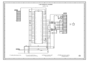
...G
LVDS SHEMATIC DIAGRAM
(DIGITAL PCB)
C2591 0.1 B
C2593 0.1 B C2592 6.3V 220
V-S
C2594 0.1 B
3.3 Vcc
1
28 27 26 25 24 23 22 21 20 19 18 17 16 15 14 13 12 11 10 9
R7
2
3.3 TxIN5
R5
3
3.3 TxIN6
...220
V-S
B2502 FCM1608KF-151T06
R2507 180
B2503
FCM1608KF-151T06
B2504
FCM1608KF-151T06
CD7201 CHRU1301
LCD PANEL
V2301 LK255T3LZ5AZ
C2595 6.3V 220 V-S
NOTE:THE DC VOLTAGE AT EACH PART ...
Service Manual - Page 41
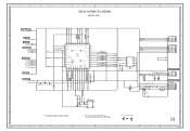
...TO FLASH
TX_[X242]
RX_[X242]
FROM/TO FRONT END AFT_1 AFT_2 SD-H AFT
5
FROM/TO POWER3
DTV_ON-H LIGHT_CTL
LCD-H INVETER_H POWER_ON-H POWER_FAIL
P.CON+5V
4
FROM/TO SOUND
POWER_ON_MUTE_H
5.0 LCD_ON
5.0 LCD_H
5.0 NC NC
0 NC NC...NC
0 REMOCON_IN
5.0
LED-H DTV_ON-H POWER_ON-H
C102 0.01 B
R104
100
33 32 31 30 29 28 27 26 25 24 23
44 43 42 41 40 39 38 37 36 35 34
5.0
VAREF
NC
NC
0
5.0
...
Service Manual - Page 42

...Y_SYNC-SEPA
I2C_DATA
SW_Y/CVBS_OUTR743 C726
75 6.3V 330 V-S 3.6 3.0
0 BUFFER
Q701 KTA1504S_Y_RTK
R719 470 R761 470
SIF/BB
INPUT
2.2
C912 0.001 B
W801
SIF
NOISE DET
0 NC NC
SAP DET L+R REF
VCC
5.0
C914
0.1 B
PLL
...
BUFFER Q702
3.0
KTA1504S_Y_RTK 0
R718 470 R742 470
C725 1B 36 35 34 33 32 31 30 29 28 27 26 25 24 23 22 21 20 19
C721
0.01 B C722
0.01 B C723
0.01 B C724
0.01 B
...
Service Manual - Page 48

...+5V
3
STANDBY LED 4
POWER ON LED 5
OS 32
CD2201_1 CU256001
PCBDA0 CEF275
R2217 10
R2201 390
R2213 10
C2203 0.01 B
R2214 10
(OPERATION PCB)
SH INPUT SW2202_3 EVQ21505R SH VOL DOWN SW2206_3 EVQ21505R C2201 0.01 B
R2207_2 390
R2203_2 1.2K
R2202_2 2.2K
R2212 5.6K
R2206_2 820
C2202 0.01 B
FROM/TO MICON
CP2203_1...
Service Manual - Page 49

...GND
7
7
GND
GND
7
SW+12V 8
8
SW+12V
GND
8
7
SW+12V 9
9
SW+12V
GND
9
LCD+B
10
10
LCD+B
GND
10
POWER_ON_H 11
11 POWER_ON_H
Analog/Dimming 11
LIGHTE_CTL 12
12 LIGHTE_CTL
ON/OFF
12
INVETER_H 13
13 INVETER_H
PWM/Dimming ... LA NOMENCLATURE DES PIECES
C
D
TO LCD PANEL CD7201
LCD PANEL V2301
E
21
GND
22
NC
23
GND
24
GND
25
GND
26
GND
27
GND
28 VDD+5V
29 ...
Similar Questions


How Do You Unlock A Sharp Television Mod 29s-fx10ldo You Need A Code
(Posted by dhanasarsoobhag 10 years ago)

How Do I Connect A System To My Tv?
what cables go were like in wich input
what cables go were like in wich input
(Posted by nancydora510 12 years ago)

Manual For Sharp Lc26sh12u Lcd Tv
We had the TV mounted on the wall, but now want to stand it up and my husband misplaced the stand. I...
We had the TV mounted on the wall, but now want to stand it up and my husband misplaced the stand. I...
(Posted by dooleytree 13 years ago)
My Sharp Lc-26sh12u Will Not Work Through My Stero System On Channel 60.
I have hooked up my sharp T.v. to my Philips stero system through both the digital input and regular...
I have hooked up my sharp T.v. to my Philips stero system through both the digital input and regular...
(Posted by sailrv88 13 years ago)