Sharp LC-26SB14U Support Question
Sharp LC-26SB14U Support Question
Find answers below for this question about Sharp LC-26SB14U - 26" LCD TV.Need a Sharp LC-26SB14U manual? We have 1 online manual for this item!
Question posted by rockboy94 on October 8th, 2010
Ps3 Not Working
Hi my question is that my ps3 is not working in ether input 4 or 5 and I do not know why it will not display. Audio works fine through the tv but the visual will never get through.
Current Answers
Related Sharp LC-26SB14U Manual Pages
Service Manual - Page 1
... replace these parts with " ! Be sure to be used . The contents are important for
SHARP CORPORATION after sales service only.
SERVICE MANUAL
No.S480ILC26SB14
LCD COLOR TELEVISION
MODEL LC-26SB14U
In the interests of user-safety (Required by safety regulations in some countries) the set should be used for maintaining the safety of the...
Service Manual - Page 2
... MODEL NUMBER can be used .
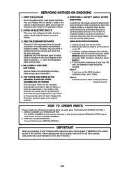
4. IMPORTANT
When you order parts. (Particularly the VERSION LETTER.) 1. BE CAREFUL WITH THE LCD PANEL
Avoid a shock to service are indicated with a heat sink, apply silicon grease (YG6260M) on the TV. 3. Unplug the plug from the AC outlet. 2.
USE THE DESIGNATED PARTS
The parts in order to the...
Service Manual - Page 4
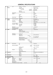
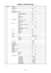
GENERAL SPECIFICATIONS
G-1 TV System
G-2 Tuning System
G-3 Signal
LCD
LCD Size / Visual Size
LCD Type
Number of Pixels
View Range
Left...Preset CH
Stereo/Dual TV Sound
Tuner Sound Muting
Video Signal
Input Level
Output Level
S/N Ratio (Weighted)
Horizontal Resolution at DVD Mode
RGB Signal
Output Level
Audio Signal
Input Level
Output Level
at DVD
at TV
Digital Output Level
S/N...
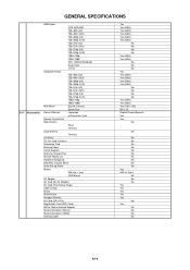
Service Manual - Page 6
...Auto Setup(Language/CH Program)
Picture Setting(TV)
AV Mode(Picture Preference)
Brightness ,...Audio Out
Tuning
CH Program
Air/Cable
ADD/DELETE
Label
CH Label
Video Label
Favorite CH
V-Chip
Type
RRT Setup
Lock
Hotel Lock
Channel Lock
Video Lock
Panel...Freeze frame
PIP/POP
Direct Input Selection
Digital Out
Dolby Digital
MPEG
PCM
DTS
PC Monitor Input
VGA (640x480)
VGA (...
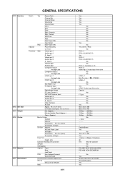
Service Manual - Page 7
... (4:3)
720×576p (16:9)
1280×720p
1920×1080i
CEC (ORION Standard)
Deep Color
xvYCC
Component Input
720×480i (4:3)
720×480i (16:9)
720×480p (4:3)
720×480p (16:9)
720×...
UM size x pcs
OEM Brand
AC Adapter
AC Cord (for AC Adapter)
AC Cord (Flat Polarity Plugs)
Cable Cramp
Stand
Stand Screw
Hexagon Wrench
AV Cord (2Pin-1Pin)
Registration Card ...
Service Manual - Page 8
...Front
Rear
Jack Panel
PCB
Non-Halogen ...Input 2
Video Output
Audio Output
Component Input 1
Analog Audio
Component Input 2
Analog Audio
HDMI Input 1
Analog Audio
HDMI Input 2
Analog Audio
Sub Woofer Out
PC Monitor Input
Analog Audio
Digital Audio Output
DC Jack (Center +)
VHF/UHF Antenna Input
Video Input 3
Audio Input 3
S - W x D x H (mm)
w/o Handle, Stand Approx.
Input...
Service Manual - Page 9
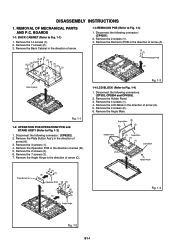
... 6. REMOVAL OF MECHANICAL PARTS AND P.C. Remove the 7 screws (3). 7. Remove the LCD Block in the direction of arrow (A). 5. Remove the 4 screws (1). 4. Remove the...Panel. 3. Disconnect the following connector: (CP6202). 2. Remove the 14 screws (1). 2. Remove the 2 screws (1). 3.
Holder Panel
Angle Main (2)
(2) (2)
(2)
(1) Angle Main (1) (1)
LCD Block
(1)
(A)
Holder Panel...
Service Manual - Page 10
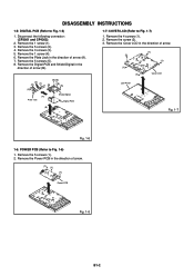
... in the
direction of arrow.
(1) (1)
(1)
(1)
(1)
Power PCB
Fig. 1-6
B1-2 Remove the Power PCB in the direction of arrow.
(2)
(1) (1)
(1) (1)
Cover LCD
LCD Panel
(B)
Fig. 1-7
Fig. 1-6
1-6: POWER PCB (Refer to Fig. 1-7)
1. Remove the Digital PCB and Shield Digital in the direction of arrow (A). 7. Remove the 1 screw (4). 6. Remove the 5 screws (1). 2. ...
Service Manual - Page 11
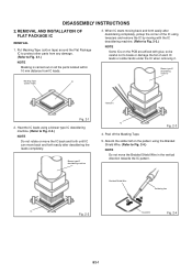
...NOTE
Some ICs on all the parts located within 10 mm distance from IC leads.
3. REMOVAL AND INSTALLATION OF FLAT PACKAGE IC
REMOVAL
1. Heat the IC leads using a blower type IC desoldering machine. (Refer to Fig. ... or solder lands under the IC when removing it. Put Masking Tape (cotton tape) around the Flat Package IC to protect other parts from any damage. (Refer to Fig. 2-2.) NOTE Do not ...
Service Manual - Page 13
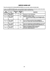
...TV data. NOTE: If you can repair, examine and adjust easily.
Check of the SUM DATA and MICON VERSION on the screen.
Power ON
VOL. Refer to the "WHEN REPLACING EEPROM (MEMORY) IC". DOWN (Minimum)
9
2 sec. 2 sec.
Refer to the "WHEN REPLACING EEPROM (MEMORY) IC". Display... enter to the "ELECTRICAL ADJUSTMENT" (On-Screen Display Adjustment). Initialization of V-CHIP PASSWORD.
2 sec....
Service Manual - Page 14
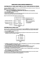
...Micon check version
EEPROM check version Parameter
CHECK SUM: 3ED6 LCD PWR ON: 0000 SUB: DA0E782141 DTV: CA09E83052 EEPROM: ... LEFT/RIGHT button to minimum. 3. Repeat steps 4 to finish DATA input. After the finishing of the initializing of each check sum, turn off...blink". 6. Total hours are displayed in 16 system of shipping. 10. NOTE: If you back to the TV mode. 2. Press both VOL...
Service Manual - Page 15
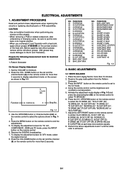
...control to set in Fig. 1-1.
To display the adjustment screen for more than 2 seconds to minimum. 2. Press the CH. D-1 Pattern Generator
On-Screen Display Adjustment
1. FUNCTION 31 BAK LIGHT MIN 32...1-2 and
press the channel button (03) on the remote control for TV, AV, COMPONENT, HDMI and PC mode, press the INPUT button on this chassis.
• When removing a PCB or related ...
Service Manual - Page 16
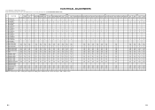
...1024 1440*900 480i
480p
720p 1080i
Step No. Step No. Step No. Step No. FUNCTION
AV
COMPONENT
HDMI
PC
TV
GAME
CVBS Y/C
480i/576i 480p/576p 720p 1080i 480i/576i 480p/576p 720p 1080i VGA 640x480 1280x720 640*480 720*400... Value (Step No.) Please check if the fixed values of each of the set correctly referring below. (TV/AV/COMPONENT/HDMI/PC/DTV)
NO. Step No. Step No.
Service Manual - Page 18
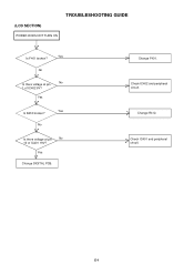
No
Is there voltage at pin 1 of IC401 19V? Check IC402 and peripheral circuit. Yes
Yes Is R412 broken?
Change F401. Check IC401 and peripheral circuit.
Change R412. (LCD SECTION)
POWER DOES NOT TURN ON
TROUBLESHOOTING GUIDE
Yes Is F401 broken?
No
No Is there voltage at pin
No
10 of IC402 6V?
E-1 Yes
Change DIGITAL PCB.
Service Manual - Page 20
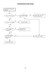
...Is there signal at pins 13, Yes 14, 16, 17, 19, 20, 22, 23, 25 and 26 of CP2804 5V? Check IC407 and peripheral circuit.
Yes
Is there voltage at pins 1, No 2, 3, 4 ...
Is there voltage at pins No 1, 2, 3, 4 and 5 of CP2804?
Yes
Connected CD2804. Change V2301 (PANEL). E-3 TROUBLESHOOTING GUIDE
THE PICTURE DOES NOT APPEAR
No Does backlight shine?
Yes
No Is CD2804 connected?
Service Manual - Page 22
...
5
14
15
SOUND +B
2
1 IC407 DC/DC(5V) LA5779-E
FEED BACK
IC408
SW
PS2561AL1-1-V(W)
41 32
31
CP401__1.TUNER+30V CP401__7.8. LCD_H
REGULATOR IC403 KIA431A-AT
F-1
F-2 LCD+B CP401__13. POWER FAIL CP401__6.P.CON+5V CP401__3. AT+5V CP401__2. SYS_POWER_H
CP401__18.SW+12V CP406__1,2,3,4,5. +24V SOUND AMP IC302 AN17808B CP401__11,12.
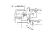
Service Manual - Page 29
... 076B0MQ051
BT002 GR6M
7
TO HDMI
6
HDMI_SW
5
4
FROM/TO SCALER VIDEO/AUDIO
IIC_OFF I2C_DATA I2C_CLK
3
FROM SURROUND A_MUTE
FROM/TO MICON
ASEMD0
2
IIC_OFF RESET_N
...DQ9 DQ1 DQ8 DQ0 OE# VSS CE# A0
R2802
10K
3.4 3.4 0 3.4 3.4 3.4 3.4 3.4 3.4 3.4 3.4 3.4 3.4 3.4 3.4 3.4 3.4 3.4 3.4 3.4 3.4 0 3.4 3.4
25 26 27 28 29 30 31 32 33 34 35 36 37 38 39 40 41 42 43 44 45 46 47 48 R2806 10K
R2805...
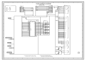
Service Manual - Page 33
.../GND 29
GND
28
LVDS0OUT0M E19 1.5 LVDS0OUT0P F19 1.5
NR2811 CRA108220JV
LCD_TXOUT0LCD_TXOUT0+
GND
27
RXIN0- 26
RXIN0+ 25
FROM REGULATOR2
B2806
HCB1608KF-221T20
D3.3V
B2807
HCB1608KF-221T20
6
C2865 10V 22 V-S... 23
RXIN1+ 22
GND
21
RXIN2- 20
CD2804
V2301_1 V260B1-L01_M
RXIN2+ 19
CURU1704
LCD PANEL
6
GND
18
RXCLK IN- 17
RXCLK IN+ 16
PLL POWER LVDS_CH0
D1.0V VDD_PANEL
...
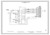
Service Manual - Page 49
...CVBS_IN_1
J4206
3245
H1 H2 H3
NC
CD3805
J401
2
BLACK
1
WHITE
PC/DVI AUDIO IN J4201
567 12
34
CP401
TUNER+30V 1 1
POWER_FAIL 2 2
SYS_POWER_H ...RXIN1+
22
RXIN1-
23
GND
24
RXIN0+
25
RXIN0-
26
GND
27
GND
28
VDD+3.3V/NC/GND 29 NC VDD...6 RESET_N 7 FLASH_WP 8 ASEMD0 9 GND 10 VDD33 11 GND 12
CD2804
V2301_1 LCD PANEL
24
DIGITAL PCB PCBDH0 CEG352
SIF-out 5
AGC 7 NC V_OUT 8
+5V ...
Service Manual - Page 55
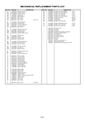
...'Y COVER LCD SPRING EARTH
107
8965TS1210 CUSHION W10/H12/L10
108
761WSA0459 SHIELD IC
109
706WPA0027 COVER CONNECTOR
110
706WPA0033 PLATE POWER
111
899RFC21V0 HOLDER CORD
112
752WSA0705 SHIELD DIGITAL
113
753WUA0063 SPRING EARTH
114
761WPAA183 HOLDER PANEL
115
761WPA0473 HOLDER SPEAKER-L
116
761WPA0474 HOLDER SPEAKER-R
117
761WPA0477 COVER HINGE
118
723000D908...
Similar Questions

How To Fix A Sharp Lcd Tv Wont Power On Model Lc 26sb14u
(Posted by lilKo 9 years ago)

White Screen Problem With Lcd Tv Lc26sb14u
How to troubleshoot and repair ?
How to troubleshoot and repair ?
(Posted by thl748 11 years ago)

Sharp 26' Lcd Lc-26sb24u
I have a shrp 26" LCD tv model LC-26SB24U the the green light will come on for about 15-20 sec. then...
I have a shrp 26" LCD tv model LC-26SB24U the the green light will come on for about 15-20 sec. then...
(Posted by awoliver86 12 years ago)

Lcd Tv -- Lamp
Does the sharp LC42SB45UT LCD TV contain a lamp?The Sharp warranty will not cover a tech to come out...
Does the sharp LC42SB45UT LCD TV contain a lamp?The Sharp warranty will not cover a tech to come out...
(Posted by kles 12 years ago)
My Electric Fuse Blew And My Tv Won't Work, Is It Broken?
(Posted by njt8383 12 years ago)