
Sharp CD-E55 Support Question
Sharp CD-E55 Support Question
Find answers below for this question about Sharp CD-E55.Need a Sharp CD-E55 manual? We have 1 online manual for this item!
Question posted by egardner2010 on January 1st, 2012
Cant Hear Music
what does it mean when the front was flashing "protected"? We are unable to hear anything from the speakers now
Current Answers
Related Sharp CD-E55 Manual Pages
Service Manual - Page 1
... contents are subject to those specified be used . S3333CDE500//
Illustration CD-E500/E55 Illustration CD-E44
MINI COMPONENT SYSTEM
MODEL CD-E500
CD-E500 Mini Component System consisting of CD-E55 (main unit) and CP-E55 (speaker system). MODEL CD-E44
CD-E44 Mini Component System consisting of CD-E44 (main unit) and CP-E44 (speaker system).
• In the interests of user-safety the set...
Service Manual - Page 2
... 50 dB (TAPE 2, recording/playback) 0.3 % (WRMS)
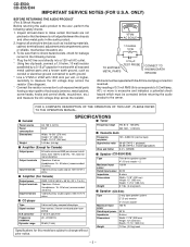
s Speaker (CD-E500/E55)
Type
Maximum input power Rated input power Impedance Dimensions
Weight
Twin-drive speaker system 4" (10 cm) woofer 2 100 W
50 W 8 ...audio product to all protective devices such as conduit or electrical ground connected to earth ground. * Use a VTVM or VOM with the AC line cord plug connection reversed. CD-E500 CD-E55...
Service Manual - Page 3
... Fast Forward, Tape 2 Fast Forward,
23
Tuner Preset Up Button
24 25
CD-E500/E55
12
3
10 11
1
2 3
1 2 1
45 67 8 9
12 13
4 5
2
s Display
1. 1
2 3 4 5 6 7 8 9 10 11
18 19 20 21
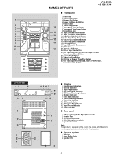
NAMES OF PARTS
CD-E500 CD-E55/E44
s Front panel
1. Timer Recording Indicator 9. Video/Auxiliary (Audio Signal) Input Jacks 2. Timer Set Indicator
3. Disc Number Indicators 2. FM Stereo...
Service Manual - Page 4
...Audio Signal) Input Jacks 2. FM/AM Loop Antenna Jack 5. CD or Tape Stop Button
15
10. Tuning and Time Up Button
17. Sleep Indicator
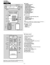
s Rear panel
1. Tape Record Indicator 13. Speaker... for better heat radiation. CD-E500 CD-E55/E44
CD-E44
12
3
10 11
1
2 3
1
2
2
3
45 67 8 9
12 13
4 5
4
s Display
1. CD Play Indicator 3. Extra Bass Indicator 8. CD Pause Indicator 11. Bass Reflex...
Service Manual - Page 5
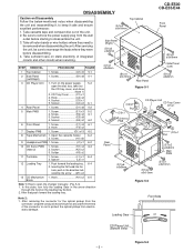
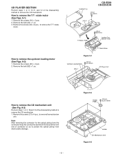
... the unit. 3. Figure 5-3 DISASSEMBLY
CD-E500 CD-E55/E44
Caution on the loading tray bottom. 2. Take off nylon bands or wire holders where they were before starting to protect the optical pickup from the wall
outlet...x2 ø3x16mm
Side Panel (Left)
(B1)x2 ø3x8mm
(C2)x1 Pull
(C3)x1 CD Servo PWB
Rear Panel
CD Player Unit CD Tray Cover (C1)x1
2 1
1
2 (C2)x1 Pull
(E1)x2 ø3x6mm
Main ...
Service Manual - Page 6
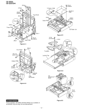
...)x1
Screwdriver (M1)x1
Display PWB
(H1)x8 ø3x8mm
Open
(J1)x1 ø2.5x10mm
Headphones PWB Holder PWB
Figure 6-2
Cassette Holder
Tape Mechanism
Figure 6-4
CD Mechanism Block
Hook (N1)x1
Pull
CP-E500/E55/E44 These speakers CP-E500,CP-E55,CP-E44 are available in assembles only and may not be disassembled.
- 6 -
Service Manual - Page 7
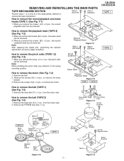
... remove the motor
bracket. 3. Remove the screws (D2) x 3 pcs., to remove the motor.
(B1)x2 ø2x8mm
Erase Head Record/ Playback Head Figure 7-2 TAPE 1 TAPE 2
CD-E500 CD-E55/E44
TAPE 1
TAPE 2
How to remove the pinch roller (TAPE 1,2) (See Fig. 7-3)
1. When you remove the screws (B2) x 2 pcs., the record/ playback head can...
Service Manual - Page 8
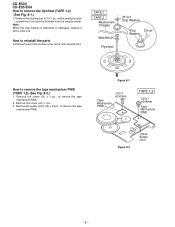
... the solder joints (J3) x 2 pcs., to remove the flywheel (TAPE 1,2) (See Fig. 8-1.)
1. Remove the stop washer is deformed or damaged, replace it with a new one. CD-E500 CD-E55/E44 How to remove the tape
mechanism PWB.
Note: When the stop washer (H1) x 1 pc., with care.
Service Manual - Page 9
...
Figure 9-2
Holder PWB
(C1)x4 ø2.5x10mm
Holder CD Mechanism Unit Figure 9-3 How to remove the T/T rotate
motor. CD-E500 CD-E55/E44
Loading Tray
(A1)x2 ø2.4x3mm
(A2)x1...)x2 ø2.4x5mm
(B2)x1
CD Player Unit
How to remove the CD mechanism unit (See Fig. 9-3)
Perform steps 1, 2, 3, 10and 13 of connector so as to protect the optical pickup from electrostatic damage....
Service Manual - Page 10
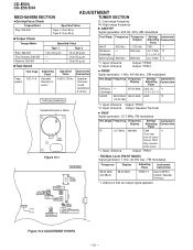
... *1 1.3 V ± 0.1 V
TAPE MECHANISM Variable Resistor in motor.
3,000 ± 30 Hz
Speaker Terminal (Load resistance: 8 ohms)
Test Stage Frequency Frequency Display
Setting/ Instrument Adjusting Connection
Point
FM Band...: Speaker Terminal
*1. former T304
fully counter-
Coverage
AM Tracking 990 kHz
*1.
clock wise)
*1. Adjust so that an output signal appears. CD-E500 CD-E55/E44...
Service Manual - Page 11
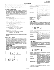
...this case, the main unit buttons are different depending on the laser. TEST MODE
CD-E500 CD-E55/E44
The test mode applied to the ordinary standby mode. In this button is... Mode (TEST 4
TIMER/SLEEP + VOLUME DOWN 5. FL Test Mode (TEST 5
CLOCK + VOLUME DOWN 6. CD MECHANISM Aging Test Mode (TEST 8) ........
MEMORY/SET + VOLUME DOWN
Press the following buttons to be pressed.(Focus...
Service Manual - Page 12
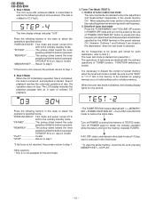
... reaches the outermost periphery of ordinary CD playback.
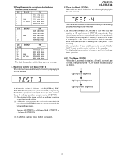
3. Tuner Test Mode (TEST 2) 1.
Return to step 5
*If the focus is not received, the process returns to protect the memory of preset memory when ...BY" button to store the adjustment and measurement frequencies in the preset memory CH. CD-E500 CD-E55/E44
4. Step 4 Mode The CLV servo ON command (8600) is transmitted to...
Service Manual - Page 13
.... The display during operation is executed at a rate of ordinary timer operation.
6. Then pressing the "PLAY" button switches display as that of one second.
CD-E500 CD-E55/E44
5. After completion of even segments
- 13 - Lighting of all the FL segments are the same as those of one step for one second, and...
Service Manual - Page 14
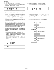
..., and an electric lid are not always provided with SURROUND (HAVE OR NOT), and electric CD lid, the following is checked whether all the main unit buttons can be used are detected as..., types of test result is shifted to be detected.
CD-E500 CD-E55/E44
7. PLAY, X-BASS/DEMO, FUNCTION, VOLUME UP/ DOWN, MEMORY/SET, REW, FF, STOP, CD-OPEN/ CLOSE
The OK/NG display of buttons to the...
Service Manual - Page 17
... MOTOR
SO101 SPEAKER TERMINAL
Q103 Q104
6 R-OUT
7 10 L-OUT 11
RLY101
Q107 +B2
Q208
JK101 HEADPHONES
F901
+B2
5A/125V
+B4 CD+B Q207
Q206... (2/4) - 17 - CD-E500 CD-E55/E44
FROM DISPLAY SECTION
CNS102
FROM DISPLAY SECTION
CNS202
202 54321
FROM CD SECTION
CNS204
CNP204 123456
CNP102...
CD L 12 R 13
DI 1
CE 2
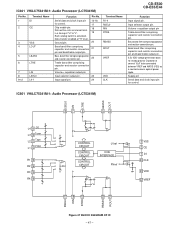
IC601
CL 24
LC75341M
21 R
AUDIO PROCESSOR 4 L
7 8 17 18 3 23
+B2...
Service Manual - Page 25
...C128 0.1 R137 4.7
C146 0.0047 C145 0.0047 R138 4.7 C127 0.1 C125 0.1
L105 2.2µH
SO101 SPEAKER TERMINAL + - D
2
1
CNP203 CNS203 33 22 11
M
M101(204-4) FAN MOTOR
JK101 HEADPHONES
...
R624 12K R625 12K
CD R TUN R TAPE R
C606 10/16
R604 1K
IC601 LC75341M
AUDIO PROCESSOR
R1 L1 R2...IN2
+VCC
NF1 N.C.
_
CD-E500 CD-E55/E44
CNP601 D604 1N4148 D605 1N4148
SO601 VIDEO/AUX IN
O MAIN PWB(2/3)...
Service Manual - Page 40
CD-E500 CD-E55/E44
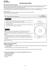
TROUBLESHOOTING
When the CD does not function
The CD section may be played
1. Before attempting any excess fluid with a soft cloth.
Do not touch the lens with the DSP).
2. Place the CD cleaner disc onto the CD...(3) Spin system check (4) PLL system check (5) Others
- 40 - You will hear music for 30-50 operations, however if the brushes become very wet then wipe off ...
Service Manual - Page 47
...23
Input signal pin.
24
Terminal Name R1-4 RSEL0 RIN RTRE
RBASS ROUT
VREF
VDD CLK
CD-E500 CD-E55/E44
Function
Input signal pin. Input selector output pin. Capacitor of "H" to be connected ... several 10µF to "L". IC601 VHiLC75341M-1: Audio Processor (LC75341M)
Pin No. IC601 VHiLC75341M-1: Audio Processor (LC75341M)
LSEL0 LIN LTRE LBASS LOUT
L4 9 CD L3 10 Tuner L2 11 Tape L1 12 ...
Service Manual - Page 51
...J .. CAUTION:FOR CONTINUED PROTECTION AGAINST FIRE HAZARD, REPLACE ONLY WITH SAME TYPE F901,...CD-E500 CD-E55/E44
MINI COMPONENT SYSTEM
MODEL CD-E500
CD-E500 Mini Component System consisting of CD-E44 (main unit) and CP-E44 (speaker system). MODEL CD-E44
CD-E44 Mini Component System consisting of CD-E500 (main unit) and CP-E500 (speaker system).
MODEL CD-E55
CD-E55 Mini Component...
Service Manual - Page 60
...-1459SS•HA•C SC • SL SHARP CORPORATION AV Systems Group Audio Systems Division Higashihiroshima, Hiroshima 739-0192, Japan
Printed in any form or by any means, electronic, mechanical, photocopying, recording, or otherwise, without prior written permission of the publisher. CD-E500 CD-E55/E44
COPYRIGHT © 2003 BY SHARP CORPORATION
ALL RIGHTS RESERVED.
Similar Questions


Sharp Cd Sw330 Timer Light Flashing
my sharp cd timer light keeps flashing but unit wont turn on,how do i fix this?
my sharp cd timer light keeps flashing but unit wont turn on,how do i fix this?
(Posted by Pinkxx 5 years ago)

Is It Possible To Get A New Power Cord That Connects The Cd Player To An Outlet?
(Posted by Roxannesemonchik 9 years ago)
Can't Get My Cd To Play. Keeps Flashing 'can't Read' Help
CD mode flashing can't read. Won't let me play CD'sfhtw
CD mode flashing can't read. Won't let me play CD'sfhtw
(Posted by gerrylowe 10 years ago)

Looking For An Antenna For My Sharp Cd-e55 Mini Component System
I need a replacement antenna for my CD-E55 Mini Component System.
I need a replacement antenna for my CD-E55 Mini Component System.
(Posted by hermanmoore01 10 years ago)