Icom IC-7100 Support Question
Icom IC-7100 Support Question
Find answers below for this question about Icom IC-7100.Need a Icom IC-7100 manual? We have 2 online manuals for this item!
Question posted by peasa123 on August 19th, 2014
Ic-7100 And Avmap Geosat 6 Aprs
How do you configure the IC-7100 to use the Geosat 6 APRS GPS output? I have both and yet to get the IC-7100 to acknolwegde the GPS output of the Geosat 6 APRS device.
Current Answers
Related Icom IC-7100 Manual Pages
Instruction Manual - Page 2
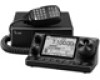
... occur. "sec. i The IC-7100 hf/vhf/uhf all mode transceiver is connected. • C onsult the dealer or an experienced radio/TV technician
for several memory storage ❍ Voice recorder to records your radio of choice, and hope you to which can radiate radio frequency energy and, if not installed and used in the internal circuit...
Instruction Manual - Page 3
...device.
DO NOT use or place the transceiver in permanent damage to the transceiver. DO NOT use harsh solvents such as benzine or alcohol to less than 16 V DC to the IC-7100 may result in an electric shock or may reduce transceiver performance and/or damage to the transceiver if left there for Human Radio...connected, set the
transceiver's RF output power to clean the transceiver, as...
Instruction Manual - Page 19
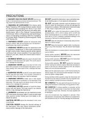
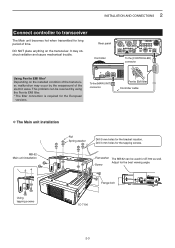
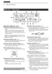
...using the CS-7100 software, DO NOT connect anything to the [REMOTE] jack.
!3 E XTERNAL SPEAKER JACK [SP] Connect to an external speaker (4 to 8 ø).
!4 MICROPHONE CONNECTOR [MIC] Plug in the DV mode. (AI sec. 9) ➥ Connect a GPS...1.1 or 2.0 port
Other items • USB cable (supplied with another IC-7100, using a mini plug cable*, for data communications, and so on other Icom ...
Instruction Manual - Page 26
...left.
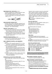
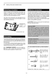
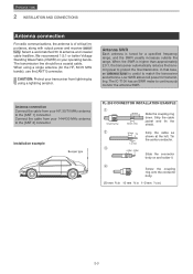
The transmission line should be a coaxial cable.
The IC-7100 has an SWR meter to the [ANT 1] connector. ...! We recommend 1.5:1 or better of arrow. When using a single antenna (for desktop use the [ANT1] connector. Slide in )
2-2
Low...of critical importance, along with output power and receiver sensitivity.
Antenna connection
For radio communications, the antenna is tuned ...
Instruction Manual - Page 27
... the best viewing angle.
Drill 3 mm holes for the European
versions.
This problem can be resolved by the wraparound of time.
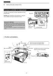
Using tapping screws
Frange bolt IC-7100
2-3 It may occur by using the Ferrite EMI filter. * The filter connection is required for the tapping screws. 2 INSTALLATION AND CONNECTIONS
Connect controller to transceiver
The...
Instruction Manual - Page 28

... Speaker)Jack
External spaeaker
Set the switch under controller to "PHONES" to use headphone and set "SP" to use external keypad. (AI sec. 17) • Data transmission (AFSK) Connect...unit when using an Electric keyer.(p. 2-5)
dot
※Set internal keyer in to use the optional HM-151 (microphone) with the IC-7000/ IC-7100 series ONLY. CAUTION: NEVER connect or use with ...
Instruction Manual - Page 29
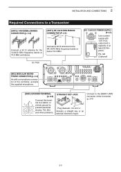
PS-126 (Optional)
[MIC] MODULAR MICROPHONE CONNECTOR (p. 2-4)
As with 13.8 V DC output and a capacity of at least 22 Amperes.
Connect a 50 Ω antenna for the 144/430 MHz frequency bands or 74.8 MHz and above. IC-7100
[DC 13.8V] DC POWER SUPPLY (P. 2-7)
Use a power supply with a microphone connector of the Controller. (p. 2-4)
2-5 Connect to the...
Instruction Manual - Page 32

...
[ACC-1] [REMOTE]
Remote Control
cable
[REMOTE]
OPC-599 conversion cable
[INPUT1] Coaxial cable
[ANT1]
[ACC]
EXCITER
1
1&2
GND
IC-PW1/EURO AC outlet
GND
Non-European versions: 100-120 / 200-240 V European version: 230 V
IC-7100
GND
DDConnecting a non-Icom linear amplifier
To connect a non-Icom HF, 50/70*1 MHz bands linear amplifier, see...
Instruction Manual - Page 36
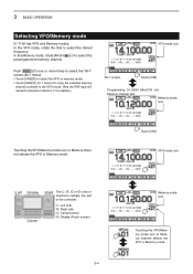
... channel selects the VFO or Memory mode.
In the Memory mode, rotate [M-CH] (L) to select the preprogrammed memory channel. 3 BASIC OPERATION
Selecting VFO/Memory mode
IC-7100 has VFO and Memory modes.
Instruction Manual - Page 37
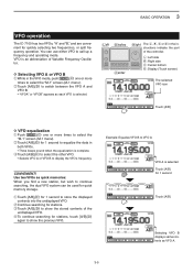
...screen (M-1 menu).
q T ouch [A/B](D) for stations, touch [A/B](D)
again to VFO A
VFO A is an abbreviation of Variable Frequency Oscillator.
Use two VFOs as each VFO is complete. DDSelecting VFO A or VFO B
qqWhile in both VFOs. • T hree beeps sound ...VFO B to store the displayed contents into the undisplayed VFO. 3 BASIC OPERATION
VFO operation
The IC-7100 has two VFOs;
Instruction Manual - Page 49
3 BASIC OPERATION
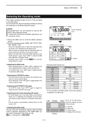
Selecting the Operating mode
The usable operating modes in the IC-7100 are listed to the right below 10 MHz, LSB is selected first.... mode selection screen and returns to exchange text messages and call signs, and transmit position data with a third-party GPS receiver. • T he DV mode is automatically selected when the DR mode is selected first; when operating below...
Instruction Manual - Page 52
3 BASIC OPERATION
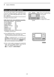
Voice synthesizer operation
The IC-7100 has a built-in voice synthesizer to "ON" in the "SPEECH" Set mode. (p. 6-4)
SET(C) > SPEECH > MODE SPEECH
Left Display Center
Right The L, R, C or D in English or ...
Instruction Manual - Page 87
...OFF or ON
Selects whether or not to the
specified level, and further rotation of the IC-7100 to pre-
30min
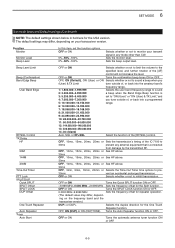
vent an accidental prolonged transmission. Function Monitor
Monitor Level Beep Level
In... the Band Edge Beep function is connected
from damage by the transmitted RF. Sets the beep output level.
SET MODE 6
Set mode items and Default settings (Continued)
NOTE: The default settings...
Instruction Manual - Page 92

... Shows the transceiver's firmware version number. Adjusts the touch screen.
Reads or writes the CS-7100 data to their default values.
6-10 Others Information Version
Clone Clone Mode
Clone Master Mode
Touch....
The default settings may differ, depending on your IC-7100 (Master) data to their default values, without clearing the memory contents, call sign memories or repeater ...
Advanced Instructions - Page 2

...used only as follows.
Push SET
Touch "Function"
Touch "Band Edge Beep"
Left Display Center
Right The L, R, C or D in the instructions indicate the
part of Adobe Systems Incorporated. and the Icom logo are registered trademarks of the IC-7100...details. If the "Beep Level" item is used in the
described steps are illustrated. The beep output level can hear a beep tone when you ...
Advanced Instructions - Page 21
... CONNECTOR 1 [ANT1] w A NTENNA CONNECTOR 2 [ANT2] (p. 2-3) Connect a 50 ø antenna with another IC-7100, using the optional CT-17 ci-v level converter, for external control of the Controller. (p. 1-15)
(+)
(_)
i ACCESSORY SOCKET... low-speed data communication in the DV mode. (p. 9-17) ➥ Connect a GPS receiver through the supplied DC power
cable. t DC POWER SOCKET [DC 13.8V] (p....
Advanced Instructions - Page 31
...(VSWR) on and solder it. The IC-7100 has an SWR meter to protect the...
shown at the left. Previous view
2 INSTALLATION AND CONNECTIONS
Antenna connection
For radio communications, the antenna is tuned for a specified frequency range, and the SWR...antenna is of critical importance, along with output power and receiver sensitivity. When the SWR is useful to the [ANT 2] connector. Low SWR allows...
Advanced Instructions - Page 32
... hot when transmitted for long period of the electric wave. It may occur by using the Ferrite EMI filter. *The filter connection is required for the European versions. This...may obstruct radiation and cause mechanical trouble. Screw
Adjust for the tapping screws.
Using tapping screws
Flange bolt IC-7100
2-4 To the [MAIN UNIT] connector
To the [CONTROLLER] connector
Ferrite EMI...
Advanced Instructions - Page 34

...)
The transceiver accepts headphones with the IC-7000/ IC-7100 series ONLY.
nal keypad by connecting the... control circuit to the MIC connector. Set the "Keyer" item in the "Connectors," and set the mode to "ON" to use the external keypad. (p. 17-25)
• Data transmission (AFSK) Connect a TNC (Terminal Node Controller) to use...
Advanced Instructions - Page 225

... data. Receing GPS data (p. 10-2) 3. Previous view
10 GPS/GPS-A OPERATION
Transmitting GPS-A data
GPS-A mode is based on APRS® code. (APRS® : Automatic...GPS is used. • The data from the internal or external GPS receiver, using the slow speed data packet space, along with the D-PRS to the IC-7100.
"MY"(Your own call sign e Time stamp* w Unproto address r Latitude
t GPS...
Similar Questions

How Can I Open The Ic 7200 For Transmission On Marine Channels?
I have been adviced that it is possible to modify so that I for safety reasons only, can trx on mari...
I have been adviced that it is possible to modify so that I for safety reasons only, can trx on mari...
(Posted by Runeedamm 4 months ago)

Ghost Tuning
Tune button flaky. Sometimes when pressing RIT on or off, radio will tune. Sometimes radio randomly ...
Tune button flaky. Sometimes when pressing RIT on or off, radio will tune. Sometimes radio randomly ...
(Posted by km4vky 10 months ago)


On The Ic-7100, Which Set Mode Item Selects Whether Or Not To Make A Communicati
(Posted by ke4uof 10 years ago)