Dell Latitude E5430 Support Question
Dell Latitude E5430 Support Question
Find answers below for this question about Dell Latitude E5430.Need a Dell Latitude E5430 manual? We have 3 online manuals for this item!
Question posted by dashshoa on May 27th, 2014
How To Remove Hard Drive On Dell E5430
The person who posted this question about this Dell product did not include a detailed explanation. Please use the "Request More Information" button to the right if more details would help you to answer this question.
Current Answers
Related Dell Latitude E5430 Manual Pages
User Manual - Page 2
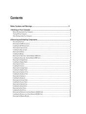
... the Keyboard Trim...12 Installing the Keyboard Trim...14 Removing the Keyboard...14 Installing the Keyboard...16 Removing the Access Panel...16 Installing the Access Panel...17 Removing the Optical Drive...17 Installing the Optical Drive...19 Removing the Hard Drive...19 Installing the Hard Drive...21 Removing the Wireless Local Area Network (WLAN) Card 22 Installing the Wireless Local Area...
User Manual - Page 19
... procedures in After Working Inside Your Computer. Remove:
a) battery b) access panel
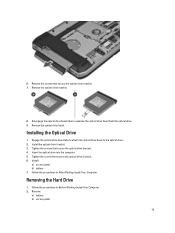
19 Installing the Optical Drive
1. Install the optical drive bracket. 3.
Insert the optical drive into the computer. 5. Removing the Hard Drive
1. Tighten the screw that secure the optical drive bracket. 7.
Tighten the screws that secure the optical drive bracket. 4. Follow the procedures in Before...
User Manual - Page 20

Use the tab to pull the hard drive bracket to release the hard drive from the computer. 20 Remove the screws that secure the hard drive bracket in place. 4. Remove the hard drive from its connector. 5. 3.
User Manual - Page 21

Install the hard drive into the computer. 4. Engage the hard drive bracket to the hard drive. 2. Tighten the screws that secure the hard drive bracket.
7. 6. Remove the hard drive bracket from the hard drive. Follow the procedures in place. 5. Remove the screws that secure the hard drive bracket. 3. Tighten the screw that secures the hard drive bracket in After Working Inside ...
User Manual - Page 31
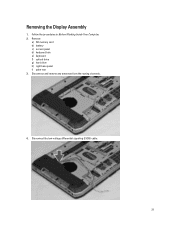
Disconnect and remove any antennae from the routing channels.
4. Removing the Display Assembly
1. Remove:
a) SD memory card b) battery c) access panel d) keyboard trim e) keyboard f) optical drive g) hard drive h) right base panel i) palm rest 3. Follow the procedures in Before Working Inside Your Computer. 2. Disconnect the low-voltage differential signaling (LVDS) cable.
31
User Manual - Page 32

... board. 4. Installing the Display Assembly
1. Route the LVDS cable along its compartment and connect the connector to their connectors. 5. Install:
a) palm rest b) right base panel c) hard drive 32 Remove the display assembly from the computer. 5. Remove the screws that secures the display assembly in place.
7. Pull the antennas through the holes on the
chassis. 3.
User Manual - Page 33
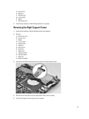
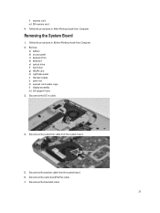
... card b) express card c) battery d) access panel e) keyboard trim f) keyboard g) optical drive h) hard drive i) WLAN card j) right base panel k) thermal module l) palm rest m) display assembly 3. Follow the procedures in Before Working Inside Your Computer. 2. Follow the procedures in After Working Inside Your Computer. Remove the screws that secure the right support frame to the computer...
User Manual - Page 34
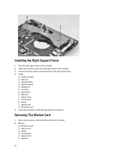
... Inside Your Computer. 2. Removing The Modem Card
1. Place the right support frame on the computer. 2. Tighten the screws to secure the right support frame to the computer. 3. Follow the procedures in After Working Inside Your Computer. Install:
a) display assembly b) palm rest c) thermal module d) right base panel e) WLAN card f) hard drive g) optical drive h) keyboard i) keyboard...
User Manual - Page 35
... the card. 5. Install:
a) right support frame b) display assembly c) express card reader cage d) palm rest e) thermal module f) right base panel g) hard drive h) optical drive i) keyboard j) keyboard trim k) access panel l) battery m) express card n) SD memory card 6. Remove:
35
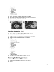
Tighten the screw to secure the modem card to the computer. 4. Connect the RJ11 cable to disengage it...
User Manual - Page 36
... the computer. 4. Installing the Left Support Frame
1. a) SD memory card b) express card c) battery d) access panel e) keyboard trim f) keyboard g) optical drive h) hard drive i) WLAN card j) right base panel k) thermal module l) palm rest m) display assembly 3. Remove the screws that secure the left support frame away from the computer. Lift the left support frame to the computer...
User Manual - Page 37
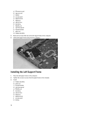
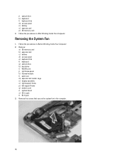
... DC-in Before Working Inside Your Computer. 2. l) express card m) SD memory card 4. Disconnect the system fan cable from the system board. 6. Remove:
a) battery b) access panel c) keyboard trim d) keyboard e) optical drive f) hard drive g) WLAN card h) right base panel i) thermal module j) palm rest k) express card reader cage l) display assembly m) left support frame 3. Disconnect the...
User Manual - Page 40
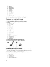
... the Coin-Cell Battery
1.
Installing the Coin-Cell Battery
1. Follow the procedures in After Working Inside Your Computer. Remove:
a) SD memory card b) ExpressCard c) battery d) access panel e) keyboard trim f) optical drive g) hard drive h) WLAN card i) right base panel j) thermal module k) palmrest l) ExpressCard reader cage m) display assembly n) left support frame c) display assembly...
User Manual - Page 41
... trim m) access panel n) battery o) ExpressCard p) SD memory card 4. Follow the procedures in Before Working Inside Your Computer. 2.
Remove:
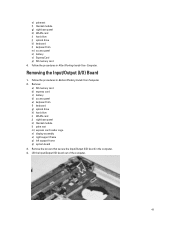
a) SD memory card b) express card c) battery d) access panel e) keyboard trim f) keyboard g) optical drive h) hard drive i) WLAN card j) right base panel k) thermal module l) palm rest m) express card reader cage n) display assembly o) right support...
User Manual - Page 42
... Working Inside Your Computer. Follow the procedures in cable from the routing channels.
42 Follow the procedures in jack
1.
Remove: a) SD memory card b) express card c) battery d) access panel e) keyboard trim f) keyboard g) optical drive h) hard drive i) WLAN card j) right base panel k) thermal module l) palm rest m) express card reader cage n) display assembly o) left support frame...
User Manual - Page 43

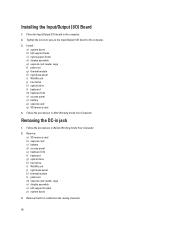
Thread the DC-in cable in Jack
1.
Installing the DC-in the routing channel. 3. Install:
a) system board b) left support bracket c) display assembly d) express card reader cage e) palm rest f) thermal module g) right base panel h) WLAN card i) hard drive
43 4. Install the DC-in jack in -jack. Remove the DC-in the computer. 2.
User Manual - Page 44
... trim m) access panel n) battery o) express card p) SD memory card 4. Follow the procedures in Before Working Inside Your Computer. 2. Remove:
a) SD memory card b) express card c) battery d) access panel e) keyboard trim f) keyboard g) optical drive h) hard drive i) WLAN card j) right base panel k) thermal module l) palm rest m) express card reader cage n) display assembly o) right support frame...
User Manual - Page 46
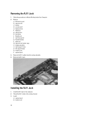
...in the computer. 2. Installing the RJ11 Jack
1. Install the RJ11 jack in the routing channel. 3. Remove the RJ11 cables from the routing channels. 4. Removing the RJ11 Jack
1. Remove:
a) SD memory card b) express card c) battery d) access panel e) keyboard trim f) keyboard g) optical drive h) hard drive i) WLAN card j) right base panel k) thermal module l) palm rest m) express card reader cage...
User Manual - Page 47

... e) display assembly f) express card reader cage g) palm rest h) thermal module i) right base panel j) WLAN card k) hard drive l) optical drive m) keyboard n) keyboard trim o) access panel p) battery q) express card r) SD memory card 4. Follow the procedures in Before Working Inside Your Computer. 2. Remove the screws to release the speakers.
47 c) left support frame r) system board 3.
User Manual - Page 59

... lists the primary hardware features of AC adapter connected to the computer
59 When the blue DELL logo is displayed, you must watch for it to display, and then press . This prompt... or set the type of hard drive installed.
System Setup
Overview
System Setup allows you to:
• change the system configuration information after you add, change, or remove any hardware in this section...
Statement of Volatility - Page 2
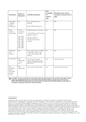
... Drives
User replaceable
Volatile memory in this text: Dell™, the DELL logo, Dell Precision™, OptiPlex™, Latitude&#...Hard drive(s)
User replaceable - User Accessible for G94 discrete graphics systems.
Non-volatile memory, 8 Mbit No (2 MB) MAC address, LED mode, WOL settings, PXE settings. May also be SSD (solid state
flash drive). Secondary power loss (removing...
Similar Questions


How To Use The Optical Drive On Dell Latitude E5430 Using The Keyboard
(Posted by chaksgre 10 years ago)


How Can I Fix Hard Drive Pipee Voice And Giving Me Msg Hard Not Installed
(Posted by engmkhalifa 11 years ago)

Remove Hard Drive Dell Vostro 1440 Laptop
how i remove hard drive dell vostro 1440 laptop step by step.
how i remove hard drive dell vostro 1440 laptop step by step.
(Posted by hiteshsethi73 12 years ago)