
Dell Inspiron One 2320 Support Question
Dell Inspiron One 2320 Support Question
Find answers below for this question about Dell Inspiron One 2320.Need a Dell Inspiron One 2320 manual? We have 3 online manuals for this item!
Question posted by mjslui on January 5th, 2014
How Connect Dell 2320 To Cable Box
The person who posted this question about this Dell product did not include a detailed explanation. Please use the "Request More Information" button to the right if more details would help you to answer this question.
Current Answers
Related Dell Inspiron One 2320 Manual Pages
Quick Start Guide (PDF) - Page 1
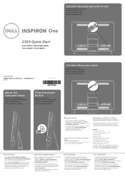
... the device(s) described in this document is subject to dell.com/ContactDell. Flat 11° Col. Connect the keyboard and mouse
Sluit het toetsenbord en de muis aan Branchez le clavier et la souris Conecte el teclado y el mouse Conecte o teclado e o mouse
One
2320 Quick Start
Snel starten | Démarrage rapide Inicio rá...
Owners Manual - Page 12
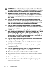
..., or install accessories.
CAUTION: When you connect a cable, ensure that shipped with locking tabs; For additional safety best practices information, see the Regulatory Compliance Homepage at dell.com/regulatory_compliance. CAUTION: To disconnect a network cable, first unplug the cable from your computer and then unplug the cable from the network device.
3 Disconnect all telephone...
Owners Manual - Page 23
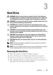
...prevent data loss, turn off your computer (see the Regulatory Compliance Homepage at dell.com/regulatory_compliance.
Hard Drive
23 Damage due to servicing that is not authorized by your ...and then disconnect the power and
data cables from sources other than Dell. CAUTION: Hard drives are installing a hard drive from a source other than Dell, you remove the hard drive from the...
Owners Manual - Page 25
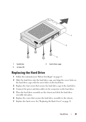
... Begin" on page 11. 2 Slide the hard drive into place. 6 Replace the screw that secure the hard-drive cage to the hard drive. 4 Connect the power and data cables to the chassis. 7 Replace the back cover.
Hard Drive
25 See "Replacing the Back Cover" on the chassis and slide the hard-drive...
Owners Manual - Page 27
....
See "Removing the Back Cover" on page 19. 3 Disconnect the power and data cables from the connector on your computer).
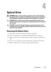
Removing the Optical Drive
1 Follow the instructions in "Before...
WARNING: Before working inside your computer, read the safety information that is not authorized by Dell is not covered by periodically touching an unpainted metal surface (such as a connector on page...
Owners Manual - Page 29
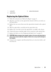
...
2 optical-drive bracket
Replacing the Optical Drive
1 Follow the instructions in damage to the computer. 8 Connect your computer and all screws and ensure that secures the optical-drive assembly to the chassis. 6 Connect the power and data cables to the optical
drive. 4 Slide the optical-drive assembly into the optical-drive bay. 5 Replace...
Owners Manual - Page 45
... screws remain inside the computer. See "Replacing the Rear-Stand Assembly"
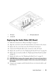
on . Audio Video Board
45 3 2 1
1 AV board 3 screws (5)
2 AV-board cables (2)
Replacing the Audio Video (AV) Board
1 Follow the instructions in damage to the computer. 8 Connect your computer and all screws and ensure that secure the AV board to the chassis...
Owners Manual - Page 47
... working inside your computer, read the safety information that is not authorized by Dell is not covered by periodically touching an unpainted metal surface (such as a...on page 39. 6 Disconnect the converter-board cable from the chassis.
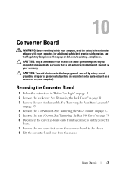
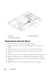
For additional safety best practices information, see the Regulatory Compliance Homepage at dell.com/regulatory_compliance. Removing the Converter Board
1 ...
Owners Manual - Page 48
... Replace the rear-stand assembly. . 1
2 3
1 screws (2) 3 converter-board connector
2 converter-board cable
Replacing the Converter Board
1 Follow the instructions in "Before You Begin" on page 11. 2 Align the ... 3 Replace the two screws that secure the converter board to the chassis. 4 Connect the converter-board cable to the connector on the converter
board. 5 Replace the rear I /O Cover" ...
Owners Manual - Page 51
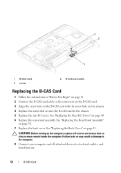
...Remove the back cover. B-CAS Card
51 Damage due to the chassis. 6 Disconnect the B-CAS card cable from the connector on the B-CAS card. 7 Lift the B-CAS card away from the computer.
11..., read the safety information that secures the B-CAS card to servicing that is not authorized by Dell is not covered by periodically touching an unpainted metal surface (such as a connector on your computer...
Owners Manual - Page 52
...
Failure to do so may result in "Before You Begin" on page 11. 2 Connect the B-CAS card cable to the connector on the B-CAS card. 3 Align the screw hole on the B-CAS...the computer. 3 2
1
1 B-CAS-card 3 screw
2 B-CAS card cable
Replacing the B-CAS Card
1 Follow the instructions in damage to the computer. 8 Connect your computer and all screws and ensure that secures the B-CAS card to the ...
Owners Manual - Page 63
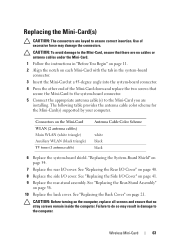
...and replace the two screws that secure the Mini-Card to the system-board connector. 5 Connect the appropriate antenna cable(s) to do so may result in the system-board connector. 3 Insert the Mini-Card... to ensure correct insertion. CAUTION: To avoid damage to the Mini-Card, ensure that no cables or antenna cables under the Mini-Card. 1 Follow the instructions in "Before You Begin" on page 11....
Owners Manual - Page 65
... the instructions in "Before You Begin" on page 83. For additional safety best practices information, see the Regulatory Compliance Homepage at dell.com/regulatory_compliance. NOTE: Record the cable routing before disconnecting the cables from the system board. See "Removing the Side I/O Cover" on
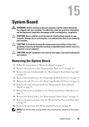
page 31. 8 Remove the Mini-Card(s). System Board
65 15...
Owners Manual - Page 66
... See "Replacing the Processor Heat-Sink"
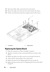
on page 84. 6 Replace the processor heat-sink. 11 Disconnect all the cables connected to the system board. 12 Remove the eight screws that secure the system board to the chassis. 13 Lift the ...chassis. 3 Replace the eight screws that secure the system board to the chassis. 4 Connect all the required cables to the system board. 5 Replace the processor.
Owners Manual - Page 75
... "Removing the System-Board
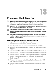
Shield" on page 53. 8 Disconnect the processor heat-sink fan cable from the connector (CPU
FAN) on the system board. 9 Remove the three screws that ...that shipped with your computer. For additional safety best practices information, see the Regulatory Compliance Homepage at dell.com/regulatory_compliance.
See "Removing the VESA Mount" on page 37. 5 Remove the rear I ...
Owners Manual - Page 76

...Before You Begin" on page 11. 2 Align the screw holes on the processor heat-sink fan with its cable away from the chassis. 10 Carefully peel the silver foil from the processor heat-sink. 11 Lift the processor... the three screws that secure the processor heat-sink fan to the
chassis. 5 Connect the processor heat-sink fan cable to the connector (CPU FAN) on
the system board.
76
Heat-Sink Fans
Owners Manual - Page 94

... the antenna modules on the chassis. 3 Replace the four screws that secure the antenna modules to the chassis. 4 Route the antenna cables through the routing guides on the chassis. 5 Connect the antenna cables to the connectors on the Mini-card. 6 Follow the instructions from step 2 to step 5 in "Replacing the Processor
Heat-Sink...
Owners Manual - Page 102
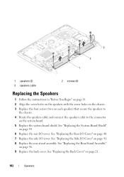
...system-board shield. See "Replacing the Side I /O cover. 3 2 1
1 speakers (2) 3 speakers cable
2 screws (4)
Replacing the Speakers
1 Follow the instructions in "Before You Begin" on page 11. 2... on each speaker) that secure the speakers to
the chassis. 4 Route the speakers cable and connect the speakers cable to the connector
on page 21.
102
Speakers See "Replacing the Rear-Stand Assembly"...
Owners Manual - Page 115

... computer.
Display
115 "Replacing the Display Assembly" on page 113. 5 Replace the display assembly. 2
3 1
1 display-panel brackets (2) 3 LVDS cable
2 display panel
Replacing the Display-Panel Brackets
1 Follow the instructions in damage to the computer. 6 Connect your computer and all screws and ensure that secure the display-panel
brackets to the display panel...
Owners Manual - Page 118
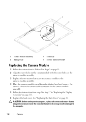
...module assembly. 4 Place the camera-module assembly on the display bezel and connect the
camera cable to the camera-cable connector on the camera-module assembly 5 Follow the instructions from step 2...Camera 2
1
3
4
1 camera-module assembly 3 display bezel
2 screws (2) 4 camera-cable connector
Replacing the Camera Module
1 Follow the instructions in "Replacing the Display Assembly" on page...
Similar Questions

How To Connect Cable Box To Dell Inspiron One 2330
(Posted by andavid 10 years ago)

How To Hook Up Cable Box To A Dell Inspiron One
(Posted by ccgarSafet 10 years ago)

Desktop Inspiron 1 2320 Black Screen When Restarting
(Posted by tmiskkevi 10 years ago)

How Do I Set Hdmi To Cable Box Dell Inspiron One 2320
(Posted by minjen 10 years ago)

How To Bypass A Bios Password On Dell Desktop Inspiron One 2320
(Posted by bexoxo 10 years ago)