
NG3 Hardware Reference
Page 26
...documentation that came with the device for setup instructions. If your computer is running at times to set up your computer uses a powerful processor which produces heat. Important If for some reason you are starting your computer: 1 Click Start, then click Turn Off Computer. We ...recommend disconnecting the power cord and modem cable when your computer Important Your computer has a built-in variable speed fan. www.emachines.com Starting your computer Starting your computer will not be used your computer for several minutes or have not turned off your computer,...
...documentation that came with the device for setup instructions. If your computer is running at times to set up your computer uses a powerful processor which produces heat. Important If for some reason you are starting your computer: 1 Click Start, then click Turn Off Computer. We ...recommend disconnecting the power cord and modem cable when your computer Important Your computer has a built-in variable speed fan. www.emachines.com Starting your computer Starting your computer will not be used your computer for several minutes or have not turned off your computer,...
NG3 Hardware Reference
Page 175
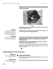
CHAPTER 13: Adding and Replacing Components www.emachines.com 4 Loosen the four captive screws that secure the heat sink... Interface Material (TIM) on page 154. 2 Disconnect the front bezel's power and LED cables from the processor. Use caution when you unpack the heat sink so you remove the heat sink from the system board. ... 1 Remove the side panel by following the instructions in "Replacing the side panel" on the corners of the processor socket, the processor could be damaged. Tips & Tricks To make note of your replacement component's front cover may vary from your ...
CHAPTER 13: Adding and Replacing Components www.emachines.com 4 Loosen the four captive screws that secure the heat sink... Interface Material (TIM) on page 154. 2 Disconnect the front bezel's power and LED cables from the processor. Use caution when you unpack the heat sink so you remove the heat sink from the system board. ... 1 Remove the side panel by following the instructions in "Replacing the side panel" on the corners of the processor socket, the processor could be damaged. Tips & Tricks To make note of your replacement component's front cover may vary from your ...
NG3 Hardware Reference
Page 180
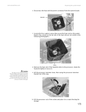
...storage. 173 Screws 8 Remove the heat sink. If the heatsink sticks to the processor, rotate the heatsink slightly to damage this material when you remove the heat sink from the system board. www.emachines.com Replacing the system board 6 Disconnect the heat sink fan power connector from ...the processor. Be careful not to loosen it. 9 Lift the processor retention lever, then swing the processor retention bracket out of the way. 10 Lift the processor out of the socket ...
...storage. 173 Screws 8 Remove the heat sink. If the heatsink sticks to the processor, rotate the heatsink slightly to damage this material when you remove the heat sink from the system board. www.emachines.com Replacing the system board 6 Disconnect the heat sink fan power connector from ...the processor. Be careful not to loosen it. 9 Lift the processor retention lever, then swing the processor retention bracket out of the way. 10 Lift the processor out of the socket ...
NG3 Hardware Reference
Page 181
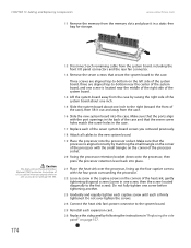
...174 12 Disconnect each of the seven system board screws you removed previously. 18 Attach all cables to the new system board. 19 Place the processor into the case. Do not fully tighten one screw before tightening another. 23 Gradually and equally tighten each captive screw until each expansion card. ...of the right side of the system board, three are aligned top-to-bottom on page 157. CHAPTER 13: Adding and Replacing Components www.emachines.com 11 Remove the memory from the memory slots and place it in the case. 17 Replace each remaining cable from the system board, ...
...174 12 Disconnect each of the seven system board screws you removed previously. 18 Attach all cables to the new system board. 19 Place the processor into the case. Do not fully tighten one screw before tightening another. 23 Gradually and equally tighten each captive screw until each expansion card. ...of the right side of the system board, three are aligned top-to-bottom on page 157. CHAPTER 13: Adding and Replacing Components www.emachines.com 11 Remove the memory from the memory slots and place it in the case. 17 Replace each remaining cable from the system board, ...


