
User Guide
Page 7
... and Off 2-4 Turning On the Computer 2-4 Turning Off the Computer 2-4 Using Your Computer Using an Optional Floppy Disk Drive 3-1 Using an Optional Media Reader 3-2 Inserting the Media 3-2 Removing the Media 3-3 Using an Optical Drive 3-4 Using Special Keys on the Keyboard 3-5 Using a Mouse ...3-6 Changing the Display Resolution and Color Depth 3-7 Controlling the Audio...
... and Off 2-4 Turning On the Computer 2-4 Turning Off the Computer 2-4 Using Your Computer Using an Optional Floppy Disk Drive 3-1 Using an Optional Media Reader 3-2 Inserting the Media 3-2 Removing the Media 3-3 Using an Optical Drive 3-4 Using Special Keys on the Keyboard 3-5 Using a Mouse ...3-6 Changing the Display Resolution and Color Depth 3-7 Controlling the Audio...
User Guide
Page 8
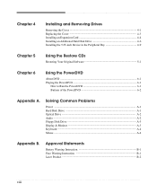
... ...A-4 Mouse ...A-4 Appendix B. Approval Statements Battery Warning Instruction B-1 Fuse Warning Instruction B-1 Laser Product ...B-2 viii Chapter 4 Installing and Removing Drives Removing the Cover 4-1 Replacing the Cover 4-3 Installing an Expansion Card 4-4 Installing an Additional Hard Disk Drive 4-6 Installing the 5.25-inch Device in the Peripheral Bay 4-9 Chapter 5 Using the Restore CDs Restoring Your Original Software...
... ...A-4 Mouse ...A-4 Appendix B. Approval Statements Battery Warning Instruction B-1 Fuse Warning Instruction B-1 Laser Product ...B-2 viii Chapter 4 Installing and Removing Drives Removing the Cover 4-1 Replacing the Cover 4-3 Installing an Expansion Card 4-4 Installing an Additional Hard Disk Drive 4-6 Installing the 5.25-inch Device in the Peripheral Bay 4-9 Chapter 5 Using the Restore CDs Restoring Your Original Software...
User Guide
Page 9
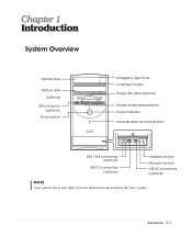
Introduction 1-1 Introduction System Overview Optical drive Optical drive (optional) USB connector (optional) Power button Emergency eject hole Load/Eject button Floppy disk drive(optional) Media reader slots(optional) Power indicator Hard disk drive access indicator IEEE 1394 connectors (optional) USB 2.0 connectors (optional) Headphone jack Microphone jack USB 2.0 connectors (optional) NOTE Chapter 1 Your optical drives may differ from the illustrations described in this user's guide.
Introduction 1-1 Introduction System Overview Optical drive Optical drive (optional) USB connector (optional) Power button Emergency eject hole Load/Eject button Floppy disk drive(optional) Media reader slots(optional) Power indicator Hard disk drive access indicator IEEE 1394 connectors (optional) USB 2.0 connectors (optional) Headphone jack Microphone jack USB 2.0 connectors (optional) NOTE Chapter 1 Your optical drives may differ from the illustrations described in this user's guide.
User Guide
Page 14
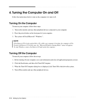
... the Start button, and then click Turn Off Computer. 3. Press the power button on your computer. 2. NOTE If the Restore CD is in the optical drive (D:) while your computer is displayed, click Turn Off to your computer, follow these steps: 1. To start Windows, remove the Restore CD and restart the computer...
... the Start button, and then click Turn Off Computer. 3. Press the power button on your computer. 2. NOTE If the Restore CD is in the optical drive (D:) while your computer is displayed, click Turn Off to your computer, follow these steps: 1. To start Windows, remove the Restore CD and restart the computer...
User Guide
Page 15
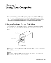
... operating system on your computer. And then slide the disk into the drive until it . To install another operating system such as shown below. When the disk pops, remove it clicks... into the drive, as OS/2 Warp or UNIX, see the manual that system for instructions on installation and ...disks before you want to remove the disk, make sure the drive light is on your system. Using an Optional Floppy Disk Drive To use your floppy disk drive, insert the diskette with that came with the label facing up...
... operating system on your computer. And then slide the disk into the drive until it . To install another operating system such as shown below. When the disk pops, remove it clicks... into the drive, as OS/2 Warp or UNIX, see the manual that system for instructions on installation and ...disks before you want to remove the disk, make sure the drive light is on your system. Using an Optional Floppy Disk Drive To use your floppy disk drive, insert the diskette with that came with the label facing up...

User Guide
Page 16
Insert only one media in a slot at one of memory cards and the IBM MICRODRIVE disk drive. Card type SD (Secure DigitalTM) MMC(MultiMediaCardTM) SM (SmartMediaTM) MS (Memory StickTM) MS-PROTM Insertion Facing up Facing up Upside down (gold contact area facing ...
Insert only one media in a slot at one of memory cards and the IBM MICRODRIVE disk drive. Card type SD (Secure DigitalTM) MMC(MultiMediaCardTM) SM (SmartMediaTM) MS (Memory StickTM) MS-PROTM Insertion Facing up Facing up Upside down (gold contact area facing ...
User Guide
Page 17
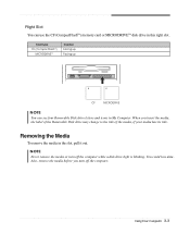
... this right slot. Also, remove the media before you insert the media, the label of the Removable Disk drive may change to the title of the media, if your media has its title. Using Your Computer 3-3 When you turn off the computer. Removing the ...Media To remove the media in My Computer. You could lose data. NOTE Never remove the media or turn off the computer while a disk drive light is blinking. Right Slot You can see four Removable Disk...
... this right slot. Also, remove the media before you insert the media, the label of the Removable Disk drive may change to the title of the media, if your media has its title. Using Your Computer 3-3 When you turn off the computer. Removing the ...Media To remove the media in My Computer. You could lose data. NOTE Never remove the media or turn off the computer while a disk drive light is blinking. Right Slot You can see four Removable Disk...
User Guide
Page 18
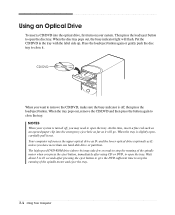
... your system is off , you may take few seconds to stop the running of the spindle motor when you have more than one hard disk drive or partition. Wait about 5 to 10 seconds after using CD or DVD, to close it out. When the disc tray pops out, the busy indicator... light will go. The high speed DVD-ROM drive (above 6x) may need to open the disc tray. Press the load/eject button again or gently push the disc tray to open the tray...
... your system is off , you may take few seconds to stop the running of the spindle motor when you have more than one hard disk drive or partition. Wait about 5 to 10 seconds after using CD or DVD, to close it out. When the disc tray pops out, the busy indicator... light will go. The high speed DVD-ROM drive (above 6x) may need to open the disc tray. Press the load/eject button again or gently push the disc tray to open the tray...
User Guide
Page 23
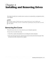
Installing and Removing Drives This chapter describes how to the computer. Then disconnect the computer from its internal components. Then disconnect any of your system to remove the cover ... cable from the electrical outlet and from any telecommunications links, networks, or modems before performing any cables connected to install or remove system cover, optional drives, and optional cards in this chapter. Installing and Removing...
Installing and Removing Drives This chapter describes how to the computer. Then disconnect the computer from its internal components. Then disconnect any of your system to remove the cover ... cable from the electrical outlet and from any telecommunications links, networks, or modems before performing any cables connected to install or remove system cover, optional drives, and optional cards in this chapter. Installing and Removing...

User Guide
Page 24
Set the cover aside. To open the system cover, remove two screws on the back panel of your system every time you touch a component. 4-2 Installing and Removing Drives NOTE Be sure to free it from the system and lift it off until can be removed completely. 3. If you are not properly grounded, you could generate an electric shock when you remove the cover. Slide the cover toward the rear to ground yourself by touching your computer. 4.
Set the cover aside. To open the system cover, remove two screws on the back panel of your system every time you touch a component. 4-2 Installing and Removing Drives NOTE Be sure to free it from the system and lift it off until can be removed completely. 3. If you are not properly grounded, you could generate an electric shock when you remove the cover. Slide the cover toward the rear to ground yourself by touching your computer. 4.

User Guide
Page 25
Installing and Removing Drives 4-3 Reconnect the monitor, keyboard, mouse, and any other peripheral device's cable connectors to the chassis with your system. Tighten the cover to your hands and gently put it down to the chassis on the rear position (about 1cm) from the front bezel, then push it to replace the cover: 1. Hold the cover with the screws you removed. 3. Replacing the Cover Follow these steps to the front. 2.
Installing and Removing Drives 4-3 Reconnect the monitor, keyboard, mouse, and any other peripheral device's cable connectors to the chassis with your system. Tighten the cover to your hands and gently put it down to the chassis on the rear position (about 1cm) from the front bezel, then push it to replace the cover: 1. Hold the cover with the screws you removed. 3. Replacing the Cover Follow these steps to the front. 2.
User Guide
Page 26
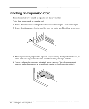
... slot cover. 3. When you want to insert it into the connector. Hold the card along the top corners and guide it fully. 4-4 Installing and Removing Drives Follow these steps to touch any switches or jumpers on the circuit board or the gold-edged connector. 4. Adjust any components on the expansion card...
... slot cover. 3. When you want to insert it into the connector. Hold the card along the top corners and guide it fully. 4-4 Installing and Removing Drives Follow these steps to touch any switches or jumpers on the circuit board or the gold-edged connector. 4. Adjust any components on the expansion card...

User Guide
Page 27
Connect any cables that should be attached to the computer with retaining screw. 6. Secure the end of the card to the card. 7. Installing and Removing Drives 4-5 Replace the system cover according to the instructions in "Replacing the Cover" in this chapter. 5.
Connect any cables that should be attached to the computer with retaining screw. 6. Secure the end of the card to the card. 7. Installing and Removing Drives 4-5 Replace the system cover according to the instructions in "Replacing the Cover" in this chapter. 5.

User Guide
Page 28
Installing an Additional Hard Disk Drive Your hard disk drive is installed in it out, as shown below. 4-6 Installing and Removing Drives Remove the system cover according to the chassis and pull it . Remove the screw securing the HDD bracket to the instructions in "Removing the Cover" in this chapter. 2. Detach all cables from the hard disk drive. HDD bracket Hard disk drive 3. You can install one additional hard disk drive in the HDD bracket attached on the chassis. Follow these steps to install the hard disk drive: 1.
Installing an Additional Hard Disk Drive Your hard disk drive is installed in it out, as shown below. 4-6 Installing and Removing Drives Remove the system cover according to the chassis and pull it . Remove the screw securing the HDD bracket to the instructions in "Removing the Cover" in this chapter. 2. Detach all cables from the hard disk drive. HDD bracket Hard disk drive 3. You can install one additional hard disk drive in the HDD bracket attached on the chassis. Follow these steps to install the hard disk drive: 1.

User Guide
Page 29
Installing and Removing Drives 4-7 Set the jumper of the new hard disk drive to the HDD bracket. With using the screws, secure the hard disk drive to CS (Cable Select). 5. 4. Slide the hard disk drive into the HDD bracket. 6.
Installing and Removing Drives 4-7 Set the jumper of the new hard disk drive to the HDD bracket. With using the screws, secure the hard disk drive to CS (Cable Select). 5. 4. Slide the hard disk drive into the HDD bracket. 6.
User Guide
Page 30
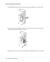
Slide the HDD bracket into the chassis and secure it .) 9. Replace the system cover according to your hard disk drive. (If you removed the hard disk drive cable from the motherboard, replace it with the retaining screw, as shown below. 8. Connect the power and hard disk drive cable to the instructions in "Replacing the Cover" in this chapter. 4-8 Installing and Removing Drives 7.
Slide the HDD bracket into the chassis and secure it .) 9. Replace the system cover according to your hard disk drive. (If you removed the hard disk drive cable from the motherboard, replace it with the retaining screw, as shown below. 8. Connect the power and hard disk drive cable to the instructions in "Replacing the Cover" in this chapter. 4-8 Installing and Removing Drives 7.
User Guide
Page 31
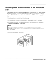
...: 1. Remove the cover according to install your hard disk drive for the 5.25-inch bay. 3. For more information, see "Installing an Additional Hard Disk Drive" in this chapter. Remove the HDD bracket from the optical drive. Installing and Removing Drives 4-9 Detach all cables from the system chassis. To install ... in the empty peripheral bay. NOTE If you want to install a 3.5-inch hard disk drive, you can add an optional device such as a CD/DVD-ROM drive, hard disk drive, LS-120 drive, or ZIP drive in the system's 5.25-inch peripheral bay, you must purchase the 5.25-inch dock ...
...: 1. Remove the cover according to install your hard disk drive for the 5.25-inch bay. 3. For more information, see "Installing an Additional Hard Disk Drive" in this chapter. Remove the HDD bracket from the optical drive. Installing and Removing Drives 4-9 Detach all cables from the system chassis. To install ... in the empty peripheral bay. NOTE If you want to install a 3.5-inch hard disk drive, you can add an optional device such as a CD/DVD-ROM drive, hard disk drive, LS-120 drive, or ZIP drive in the system's 5.25-inch peripheral bay, you must purchase the 5.25-inch dock ...
User Guide
Page 32
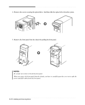
Remove the front panel from the front panel. 4-10 Installing and Removing Drives NOTES Be careful, not to split the power and LED cables from the chassis by pulling the front panel. When you remove the front panel from the chassis, you have to carefully apart the cover not to bent or break the front panel. Remove the screws securing the optical drive. And then slide the optical drive from the system. 5. 4.
Remove the front panel from the front panel. 4-10 Installing and Removing Drives NOTES Be careful, not to split the power and LED cables from the chassis by pulling the front panel. When you remove the front panel from the chassis, you have to carefully apart the cover not to bent or break the front panel. Remove the screws securing the optical drive. And then slide the optical drive from the system. 5. 4.
User Guide
Page 33
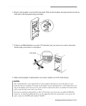
... on both ends of E-IDE cable marked "SLAVE." Make sure the jumper of optional drive you can use the spare connector of the front panel using a tool such as a screwdriver. NOTES Like a hard disk drive, most optional devices have jumpers that must set to work properly with your finger. 7.... Remove the faceplate cover from the chassis using your computer. Installing and Removing Drives 4-11 If you set for the drive to CS (Cable Select). If there is set the jumper of your system recognizes the device according to location of new...
... on both ends of E-IDE cable marked "SLAVE." Make sure the jumper of optional drive you can use the spare connector of the front panel using a tool such as a screwdriver. NOTES Like a hard disk drive, most optional devices have jumpers that must set to work properly with your finger. 7.... Remove the faceplate cover from the chassis using your computer. Installing and Removing Drives 4-11 If you set for the drive to CS (Cable Select). If there is set the jumper of your system recognizes the device according to location of new...
User Guide
Page 34
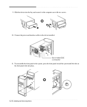
To reassemble the front panel to the system, press the front panel toward the system until the tabs on the front panel click into the bay and secure it to the device installed. Slide the device into place. 4-12 Installing and Removing Drives Connect the power and interface cables to the computer case with two screws. 10. 9. Secondary EIDE connector 11.
To reassemble the front panel to the system, press the front panel toward the system until the tabs on the front panel click into the bay and secure it to the device installed. Slide the device into place. 4-12 Installing and Removing Drives Connect the power and interface cables to the computer case with two screws. 10. 9. Secondary EIDE connector 11.

