eMachines E627 Quick Guide - English
Page 7
... adapter. 2 Ethernet (RJ-45) port Connects to an Ethernet 10/100-based network. 3 External display (VGA) Connects to a display device (e.g., port external monitor, LCD projector). 4 USB 2.0 port Connect to USB 2.0 devices (e.g., USB mouse, USB camera). 5 Microphone-in jack Accepts inputs from external microphones.
... adapter. 2 Ethernet (RJ-45) port Connects to an Ethernet 10/100-based network. 3 External display (VGA) Connects to a display device (e.g., port external monitor, LCD projector). 4 USB 2.0 port Connect to USB 2.0 devices (e.g., USB mouse, USB camera). 5 Microphone-in jack Accepts inputs from external microphones.
eMachines E627 Quick Guide - English
Page 11
...: The specifications listed above are for certain models. English 11 I/O interface Environment • Multi-in-1 card reader (SD™, MMC, MS, MS PRO, xD) • USB 2.0 port • External display (VGA) port • Headphones/speaker/line-out jack • Microphone-in jack • Ethernet (RJ-45) port • DC-in jack...
...: The specifications listed above are for certain models. English 11 I/O interface Environment • Multi-in-1 card reader (SD™, MMC, MS, MS PRO, xD) • USB 2.0 port • External display (VGA) port • Headphones/speaker/line-out jack • Microphone-in jack • Ethernet (RJ-45) port • DC-in jack...

Service Guide
Page 12
... • LAN • Atheros AR8132L for 10/100 LAN • PCI-E 10/100M LAN • WOL (AC mode S5) support • Modem • External USB 2.0 modem • Support Wake on Ring (S3) Privacy control • BIOS user, supervisor, HDD passwords • Kensington lock slot Power subsystem • 65W •...8226; Multi-language support I/O interface • VGA port, 15 pins • DC-IN port for adapter • RJ-45 Ethernet port for LAN • 2 USB port • Headphone out / Line-out • Microphone-in • Multi-in-1 card reader (SD™, MMC, MS, MS PRO, xD 2 Chapter 1
... • LAN • Atheros AR8132L for 10/100 LAN • PCI-E 10/100M LAN • WOL (AC mode S5) support • Modem • External USB 2.0 modem • Support Wake on Ring (S3) Privacy control • BIOS user, supervisor, HDD passwords • Kensington lock slot Power subsystem • 65W •...8226; Multi-language support I/O interface • VGA port, 15 pins • DC-IN port for adapter • RJ-45 Ethernet port for LAN • 2 USB port • Headphone out / Line-out • Microphone-in • Multi-in-1 card reader (SD™, MMC, MS, MS PRO, xD 2 Chapter 1

Service Guide
Page 17
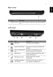
... to a display device (e.g. Accepts input from external microphones. speakers, headphones). No. 1 2 2 4 5 12 3 4 5 Icon Item DC-in jack Ethernet (RJ-45) port External display (VGA) port USB 2.0 ports Microphone-in jack Headphones/ speaker/line-out jack Description Connects to an AC adapter Connects to audio line-out devices (e.g. Connects to an Ethernet... network. Rear View 1 No. 1 Icon Item Ventilation slots Left View Description Enable the computer to stay cool, even after prolonged use. external monitor, LCD projector). USB mouse, USB camera).
... to a display device (e.g. Accepts input from external microphones. speakers, headphones). No. 1 2 2 4 5 12 3 4 5 Icon Item DC-in jack Ethernet (RJ-45) port External display (VGA) port USB 2.0 ports Microphone-in jack Headphones/ speaker/line-out jack Description Connects to an AC adapter Connects to audio line-out devices (e.g. Connects to an Ethernet... network. Rear View 1 No. 1 Icon Item Ventilation slots Left View Description Enable the computer to stay cool, even after prolonged use. external monitor, LCD projector). USB mouse, USB camera).
Service Guide
Page 41
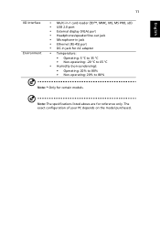
...-Menu F10 Save and Exit Chapter 2 31 Information M a i n PhoenixBIOS Setup Utility Security Boot Exit Boot priority order: 1: IDE0: ST960821A 2: IDE1: MATSHITADVD 3: USB FDD: 4: Network boot: Realtek Boot Agent 5: USB HDD: xxxx USB 6: USB CDROM: Item Specific Help Use < > or < > to select a device, then press to move it up the List, or to escape the... to load the operating system. Boot This menu allows the user to decide the order of boot devices to support boot. Bootable devices includes the USB diskette drives, the onboard hard disk drive and the DVD drive in the module bay.
...-Menu F10 Save and Exit Chapter 2 31 Information M a i n PhoenixBIOS Setup Utility Security Boot Exit Boot priority order: 1: IDE0: ST960821A 2: IDE1: MATSHITADVD 3: USB FDD: 4: Network boot: Realtek Boot Agent 5: USB HDD: xxxx USB 6: USB CDROM: Item Specific Help Use < > or < > to select a device, then press to move it up the List, or to escape the... to load the operating system. Boot This menu allows the user to decide the order of boot devices to support boot. Bootable devices includes the USB diskette drives, the onboard hard disk drive and the DVD drive in the module bay.
Service Guide
Page 44
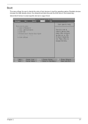
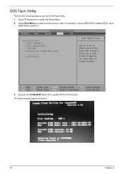
Select Boot Menu to modify the boot priority order, for example, if using USB HDD to Update BIOS, move USB HDD to update BIOS in DOS mode. F1 Help Esc Exit Select Item F5/F6 Change Values F9 Setup Defaults Select Menu Enter ...FLASH.BAT batch file to position 1. Information M a i n PhoenixBIOS Setup Utility Security Boot Exit Boot priority order: 1: IDE0: ST960821A 2: IDE1: MATSHITADVD 3: USB FDD: 4: Network boot: Realtek Boot Agent 5: USB HDD: xxxx USB 6: USB CDROM: Item Specific Help Use < > or < > to select a device, then press to move it down the list. Press to move it...
Select Boot Menu to modify the boot priority order, for example, if using USB HDD to Update BIOS, move USB HDD to update BIOS in DOS mode. F1 Help Esc Exit Select Item F5/F6 Change Values F9 Setup Defaults Select Menu Enter ...FLASH.BAT batch file to position 1. Information M a i n PhoenixBIOS Setup Utility Security Boot Exit Boot priority order: 1: IDE0: ST960821A 2: IDE1: MATSHITADVD 3: USB FDD: 4: Network boot: Realtek Boot Agent 5: USB HDD: xxxx USB 6: USB CDROM: Item Specific Help Use < > or < > to select a device, then press to move it down the list. Press to move it...
Service Guide
Page 143
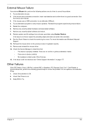
... no red Xs or yellow exclamation marks. • There are no device conflicts. • No hardware is properly installed. If the mouse uses a USB connection, try an alternate USB port. 4. If the issue is ok. 3. Do not replace a non-defective FRUs: 1. Remove and reinstall the mouse driver. 12. Remove any recently added...
... no red Xs or yellow exclamation marks. • There are no device conflicts. • No hardware is properly installed. If the mouse uses a USB connection, try an alternate USB port. 4. If the issue is ok. 3. Do not replace a non-defective FRUs: 1. Remove and reinstall the mouse driver. 12. Remove any recently added...
Service Guide
Page 150
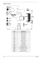
Bottom View ITEM PJP1 JRJ1 JCRT1 JP12 JUSB1 JUSB2 JMIC1 JHP1 JSATA2 U39 JCPU1 JREAD1 PJP2 JDIMM2 JDIMM1 JSATA1 JMINI2 DESCRIPTION AC-IN Connector RJ45 Connector CRT Connector Fan Connector USB Connector USB Connector MIC-In Jack Head-Phone Jack HDD Connector North Bridge CPU Socket Card Reader Socket Battery Connector Memory DIMM2 Connector Memory DIMM1 Connector ODD Connector Wireless Card Connector 140 Chapter 5
Bottom View ITEM PJP1 JRJ1 JCRT1 JP12 JUSB1 JUSB2 JMIC1 JHP1 JSATA2 U39 JCPU1 JREAD1 PJP2 JDIMM2 JDIMM1 JSATA1 JMINI2 DESCRIPTION AC-IN Connector RJ45 Connector CRT Connector Fan Connector USB Connector USB Connector MIC-In Jack Head-Phone Jack HDD Connector North Bridge CPU Socket Card Reader Socket Battery Connector Memory DIMM2 Connector Memory DIMM1 Connector ODD Connector Wireless Card Connector 140 Chapter 5
Service Guide
Page 153
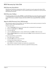
...to a successful one once the previous BIOS flashing process failed. It is included with a workable BIOS. 4. Follow the steps below: 1. Plug USB storage into the Crisis folder which is used to boot up the system with Windows XP OS. Steps for this machine by executing the Crisis... Disk program in another system with minimum BIOS initialization. Press Fn + ESC button then plug in the USB disk. 4. Press Power button to create a USB Crisis Disk. BIOS Recovery by Crisis Disk BIOS Recovery Boot Block: BIOS Recovery Boot Block is enabled, the system ...
...to a successful one once the previous BIOS flashing process failed. It is included with a workable BIOS. 4. Follow the steps below: 1. Plug USB storage into the Crisis folder which is used to boot up the system with Windows XP OS. Steps for this machine by executing the Crisis... Disk program in another system with minimum BIOS initialization. Press Fn + ESC button then plug in the USB disk. 4. Press Power button to create a USB Crisis Disk. BIOS Recovery by Crisis Disk BIOS Recovery Boot Block: BIOS Recovery Boot Block is enabled, the system ...


