eMachines E627 Quick Guide - English
Page 6
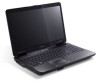
...the computer cover is charging. 2. Brightness down Decreases the sound volume. Volume down Decreases the screen brightness. Charging: The light shows amber when the battery is closed up Increases the screen brightness. English 6 Hotkey Icon + + < > + < > + < > + < > Function Description... the sound volume. Closed front view # Item Description 1 Power1 Indicates the computer's power status. Battery1 Indicates the computer's battery status. 1. Fully charged: The light shows blue when in AC mode. 2 Multi-in-1 Accepts Secure Digital (SD), ...
...the computer cover is charging. 2. Brightness down Decreases the sound volume. Volume down Decreases the screen brightness. Charging: The light shows amber when the battery is closed up Increases the screen brightness. English 6 Hotkey Icon + + < > + < > + < > + < > Function Description... the sound volume. Closed front view # Item Description 1 Power1 Indicates the computer's power status. Battery1 Indicates the computer's battery status. 1. Fully charged: The light shows blue when in AC mode. 2 Multi-in-1 Accepts Secure Digital (SD), ...

eMachines E627 Quick Guide - English
Page 9
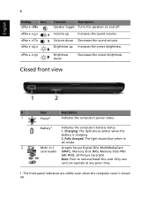
9 Base view English # Icon Item 1 Battery bay Description Houses the computer's battery pack. 2 Battery release latch Releases the battery for removal. 3 Battery lock Locks the battery in position. 4 Hard disk bay Houses the computer's hard disk (secured with screws). 5 Memory compartment Houses the computer's main memory. 6 Ventilation slots and Enable the computer to stay cool, even cooling fan after prolonged use. Note: Do not cover or obstruct the opening of the fan.
9 Base view English # Icon Item 1 Battery bay Description Houses the computer's battery pack. 2 Battery release latch Releases the battery for removal. 3 Battery lock Locks the battery in position. 4 Hard disk bay Houses the computer's hard disk (secured with screws). 5 Memory compartment Houses the computer's main memory. 6 Ventilation slots and Enable the computer to stay cool, even cooling fan after prolonged use. Note: Do not cover or obstruct the opening of the fan.
eMachines E627 Quick Guide - English
Page 10
Wake-on-LAN ready 372.3 (W) x 246.5 (D) x 26.8/39.6 (H) mm (14.4 x 10.8 x 1.1/1.5 inches) 2.7 kg (6.0 lbs.) with 6-cell battery pack BIOS user, supervisor, HDD passwords Kensington lock slot ACPI 3.0 48.8 W 4400 mAh 3-pin 65 W AC adapter ENERGY STAR® 4.0* 99-/100-/103-key keyboard ...
Wake-on-LAN ready 372.3 (W) x 246.5 (D) x 26.8/39.6 (H) mm (14.4 x 10.8 x 1.1/1.5 inches) 2.7 kg (6.0 lbs.) with 6-cell battery pack BIOS user, supervisor, HDD passwords Kensington lock slot ACPI 3.0 48.8 W 4400 mAh 3-pin 65 W AC adapter ENERGY STAR® 4.0* 99-/100-/103-key keyboard ...
Service Guide
Page 7
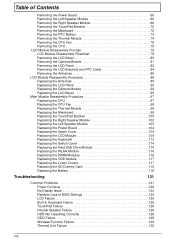
... (dual-display compatible 16 Hardware Specifications and Configurations 17 System Utilities 25 BIOS Setup Utility 25 Navigating the BIOS Utility 25 eMachines E627 BIOS 26 Information 26 Main 27 Security 28 Boot 31 Exit 32 BIOS Flash Utilities 33 DOS Flash Utility 34 WinFlash Utility... Requirements 41 Pre-disassembly Instructions 42 Disassembly Process 42 External Module Disassembly Process 43 External Modules Disassembly Flowchart 43 Removing the Battery Pack 44 Removing the SD Dummy Card 45 Removing the Lower Covers 46 Removing the Optical Drive Module 47 Removing the ...
... (dual-display compatible 16 Hardware Specifications and Configurations 17 System Utilities 25 BIOS Setup Utility 25 Navigating the BIOS Utility 25 eMachines E627 BIOS 26 Information 26 Main 27 Security 28 Boot 31 Exit 32 BIOS Flash Utilities 33 DOS Flash Utility 34 WinFlash Utility... Requirements 41 Pre-disassembly Instructions 42 Disassembly Process 42 External Module Disassembly Process 43 External Modules Disassembly Flowchart 43 Removing the Battery Pack 44 Removing the SD Dummy Card 45 Removing the Lower Covers 46 Removing the Optical Drive Module 47 Removing the ...
Service Guide
Page 8
...Removing the Left Speaker Module 66 Removing the Right Speaker Module 68 Removing the TouchPad Bracket 70 Removing the Mainboard 72 Removing the RTC Battery 73 Removing the Thermal Module 74 Removing the CPU Fan 76 Removing the CPU 78 LCD Module Disassembly Process 79 LCD Module Disassembly ...116 Replacing the DIMM Modules 116 Replacing the ODD Module 117 Replacing the Lower Covers 117 Replacing the SD Dummy Card 118 Replacing the Battery 119 Troubleshooting 121 Common Problems 121 Power On Issue 122 No Display Issue 123 Random Loss of BIOS Settings 124 LCD Failure 125 ...
...Removing the Left Speaker Module 66 Removing the Right Speaker Module 68 Removing the TouchPad Bracket 70 Removing the Mainboard 72 Removing the RTC Battery 73 Removing the Thermal Module 74 Removing the CPU Fan 76 Removing the CPU 78 LCD Module Disassembly Process 79 LCD Module Disassembly ...116 Replacing the DIMM Modules 116 Replacing the ODD Module 117 Replacing the Lower Covers 117 Replacing the SD Dummy Card 118 Replacing the Battery 119 Troubleshooting 121 Common Problems 121 Power On Issue 122 No Display Issue 123 Random Loss of BIOS Settings 124 LCD Failure 125 ...

Service Guide
Page 12
...Dimensions and Weight • 372.3mm x 246.5mm x 26.8mm/40.6mm with ID • Weight < than 3100g (15.6" LCD/6-cell battery/super-multi ODD) Communication • Wireless • 802.11b/g/n WLAN/WiMax • Mini PCIE Wireless LAN module with with mini card slot • ... control • BIOS user, supervisor, HDD passwords • Kensington lock slot Power subsystem • 65W • Universal jack for adapter • Battery: 6-cell AS2009A Special keys and controls • 99-/100-/103-key keyboard • Supports Application keys for Windows XP/Linux version • Support ...
...Dimensions and Weight • 372.3mm x 246.5mm x 26.8mm/40.6mm with ID • Weight < than 3100g (15.6" LCD/6-cell battery/super-multi ODD) Communication • Wireless • 802.11b/g/n WLAN/WiMax • Mini PCIE Wireless LAN module with with mini card slot • ... control • BIOS user, supervisor, HDD passwords • Kensington lock slot Power subsystem • 65W • Universal jack for adapter • Battery: 6-cell AS2009A Special keys and controls • 99-/100-/103-key keyboard • Supports Application keys for Windows XP/Linux version • Support ...

Service Guide
Page 16
... and right) Palmrest HDD Description The left and right buttons function like the left and right mouse buttons. Charging: The light shows amber when the battery is closed 6 Chapter 1 Indicates when the hard disk drive is active. Comfortable support area for your hands when you use the computer. Battery1 Indicates the...
... and right) Palmrest HDD Description The left and right buttons function like the left and right mouse buttons. Charging: The light shows amber when the battery is closed 6 Chapter 1 Indicates when the hard disk drive is active. Comfortable support area for your hands when you use the computer. Battery1 Indicates the...

Service Guide
Page 18
... clip into the notch and turn the key to secure the lock. Bottom View 1 2 6 3 5 4 No. 1 2 8 Icon Item Battery bay Battery release latch Description Houses the computer's battery pack. Lights up when the optical drive is off . Ejects the optical drive tray when the computer is turned off . Note: Wrap... the computer security lock cable around an immovable object such as a table or handle of a locked drawer. Releases the battery for removal. Connects to eject the optical drive tray when the computer is active. Insert the lock into the emergency eject hole to ...
... clip into the notch and turn the key to secure the lock. Bottom View 1 2 6 3 5 4 No. 1 2 8 Icon Item Battery bay Battery release latch Description Houses the computer's battery pack. Lights up when the optical drive is off . Ejects the optical drive tray when the computer is turned off . Note: Wrap... the computer security lock cable around an immovable object such as a table or handle of a locked drawer. Releases the battery for removal. Connects to eject the optical drive tray when the computer is active. Insert the lock into the emergency eject hole to ...
Service Guide
Page 19
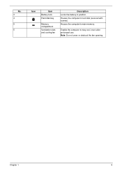
Houses the computer's hard disk (secured with screws). Chapter 1 9 Note: Do not cover or obstruct the fan opening. No. 3 4 5 5 Icon Item Battery lock Hard disk bay Memory compartment Ventilation slots and cooling fan Description Locks the battery in position. Enable the computer to stay cool, even after prolonged use. Houses the computer's main memory.
Houses the computer's hard disk (secured with screws). Chapter 1 9 Note: Do not cover or obstruct the fan opening. No. 3 4 5 5 Icon Item Battery lock Hard disk bay Memory compartment Ventilation slots and cooling fan Description Locks the battery in position. Enable the computer to stay cool, even after prolonged use. Houses the computer's main memory.
Service Guide
Page 20
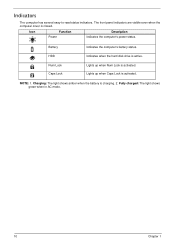
Battery HDD Num Lock Caps Lock Indicates the computer's battery status. Indicates when the hard disk drive is charging. 2. Charging: The light shows amber when the battery is active. NOTE: 1. Lights up when Num Lock is activated. Icon Function Power Description Indicates the computer's power status. Lights up when Caps Lock is activated. Indicators The computer has several easy-to-read status indicators. The front panel indicators are visible even when the computer cover is closed. Fully charged: The light shows green when in AC mode. 10 Chapter 1
Battery HDD Num Lock Caps Lock Indicates the computer's battery status. Indicates when the hard disk drive is charging. 2. Charging: The light shows amber when the battery is active. NOTE: 1. Lights up when Num Lock is activated. Icon Function Power Description Indicates the computer's power status. Lights up when Caps Lock is activated. Indicators The computer has several easy-to-read status indicators. The front panel indicators are visible even when the computer cover is closed. Fully charged: The light shows green when in AC mode. 10 Chapter 1
Service Guide
Page 32
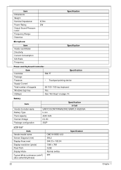
... & model name Battery Type Pack capacity Normal Voltage Package configuration Specification 6 Cell SANYO/SONY/PANASONIC/SIMPLO AS2009A Li-ion 4400 mAh 2.2 Ah 3S2P LCD 15.6" Item Vendor/model ...
... & model name Battery Type Pack capacity Normal Voltage Package configuration Specification 6 Cell SANYO/SONY/PANASONIC/SIMPLO AS2009A Li-ion 4400 mAh 2.2 Ah 3S2P LCD 15.6" Item Vendor/model ...
Service Guide
Page 43
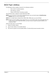
..., EMS, DPMI) when you use the AC adaptor power supply when you run the Phlash. 1. Use the Phlash utility to the bootable diskette. 3. If the battery pack does not contain enough power to run the Phlash utility. The flash utility has auto-execution function. Copy the flash utilities to update the...
..., EMS, DPMI) when you use the AC adaptor power supply when you run the Phlash. 1. Use the Phlash utility to the bootable diskette. 3. If the battery pack does not contain enough power to run the Phlash utility. The flash utility has auto-execution function. Copy the flash utilities to update the...
Service Guide
Page 52
Place the system on a flat, stable surface. 4. Remove the battery pack. Main Screw List Screw Quantity Part Number SCREW M2.5*4 1 86.N2802.001 SCREW M2.5*6 10 86.N2802.002 SCREW M2.5*8 30 86.N2802.003 ...
Place the system on a flat, stable surface. 4. Remove the battery pack. Main Screw List Screw Quantity Part Number SCREW M2.5*4 1 86.N2802.001 SCREW M2.5*6 10 86.N2802.002 SCREW M2.5*8 30 86.N2802.003 ...

Service Guide
Page 53
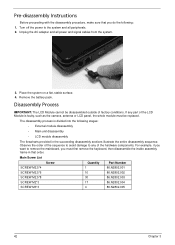
External Module Disassembly Process IMPORTANT: The outside housing and color may vary from system Rem ove Battery Rem ove Dummy Card Rem ove Lower Covers Rem ove ODD Rem ove DIMMs Screw List Step Lower Covers ODD Module WLAN Module HDD Carrier ...
External Module Disassembly Process IMPORTANT: The outside housing and color may vary from system Rem ove Battery Rem ove Dummy Card Rem ove Lower Covers Rem ove ODD Rem ove DIMMs Screw List Step Lower Covers ODD Module WLAN Module HDD Carrier ...

Service Guide
Page 54
Slide and hold the battery release latch to the release position (1), then lift out the battery pack from the main unit (2). 2 1 44 Chapter 3 Slide the battery lock in the direction shown. 2. Turn computer over. Removing the Battery Pack 1.
Slide and hold the battery release latch to the release position (1), then lift out the battery pack from the main unit (2). 2 1 44 Chapter 3 Slide the battery lock in the direction shown. 2. Turn computer over. Removing the Battery Pack 1.
Service Guide
Page 56
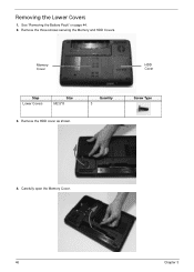
Removing the Lower Covers 1. Carefully open the Memory Cover. 46 Chapter 3 Remove the HDD cover as shown. Memory Cover HDD Cover Step Lower Covers Size M2.5*8 3. Quantity 3 Screw Type 4. Remove the three screws securing the Memory and HDD Covers. See "Removing the Battery Pack" on page 44. 2.
Removing the Lower Covers 1. Carefully open the Memory Cover. 46 Chapter 3 Remove the HDD cover as shown. Memory Cover HDD Cover Step Lower Covers Size M2.5*8 3. Quantity 3 Screw Type 4. Remove the three screws securing the Memory and HDD Covers. See "Removing the Battery Pack" on page 44. 2.

Service Guide
Page 57
Chapter 3 47 Gently lever the ODD module out of the chassis. 4. Removing the Optical Drive Module 1. Pull the optical drive module out from the chassis. Step ODD Module Size M2.5*8 Quantity 1 Screw Type 3. Insert a suitable tool into the access slot in the battery bay as shown. Remove the screw securing the ODD module. See "Removing the Battery Pack" on page 44. 2.
Chapter 3 47 Gently lever the ODD module out of the chassis. 4. Removing the Optical Drive Module 1. Pull the optical drive module out from the chassis. Step ODD Module Size M2.5*8 Quantity 1 Screw Type 3. Insert a suitable tool into the access slot in the battery bay as shown. Remove the screw securing the ODD module. See "Removing the Battery Pack" on page 44. 2.

Service Guide
Page 64
... ove Power Board Rem ove Left Speaker Module Rem ove Right Speaker Module Rem ove TouchPad Bracket Lower Cover Rem ove Mainboard Rem ove RTC Battery Rem ove Thermal Module Rem ove CPU Fan Rem ove CPU Screw List Step LCD Module LCD Module Upper Cover Upper Cover Power Board Left...
... ove Power Board Rem ove Left Speaker Module Rem ove Right Speaker Module Rem ove TouchPad Bracket Lower Cover Rem ove Mainboard Rem ove RTC Battery Rem ove Thermal Module Rem ove CPU Fan Rem ove CPU Screw List Step LCD Module LCD Module Upper Cover Upper Cover Power Board Left...

Service Guide
Page 65
... the Switch Cover upward, away from the Upper Cover. 3. Lift the Switch Cover clear of the Keyboard to remove the Switch Cover. 1. See "Removing the Battery Pack" on the right side of the computer. Press down the / and * keys on page 44. 2. Removing the Switch Cover CAUTION: Using metal tools to...
... the Switch Cover upward, away from the Upper Cover. 3. Lift the Switch Cover clear of the Keyboard to remove the Switch Cover. 1. See "Removing the Battery Pack" on the right side of the computer. Press down the / and * keys on page 44. 2. Removing the Switch Cover CAUTION: Using metal tools to...
Service Guide
Page 83
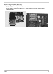
To replace the battery, solder the new battery to the Mainboard. Removing the RTC Battery IMPORTANT:Follow local regulations for disposal of all batteries. The RTC Battery is soldered to the connections shown. Chapter 3 73
To replace the battery, solder the new battery to the Mainboard. Removing the RTC Battery IMPORTANT:Follow local regulations for disposal of all batteries. The RTC Battery is soldered to the connections shown. Chapter 3 73


