eMachines E627 Quick Guide - English
Page 5
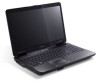
... Left and right speakers deliver stereo audio output. 5 Keyboard For entering data into your hands when you use the computer. 9 HDD Indicates when the hard disk drive is activated. Switches display output between the display screen, external monitor (if connected) and both. Turns the display screen backlight off to return. Wireless LAN...
... Left and right speakers deliver stereo audio output. 5 Keyboard For entering data into your hands when you use the computer. 9 HDD Indicates when the hard disk drive is activated. Switches display output between the display screen, external monitor (if connected) and both. Turns the display screen backlight off to return. Wireless LAN...
eMachines E627 Quick Guide - English
Page 10
... MHz memory, upgradeable to 4 GB using two soDIMM modules 15.6" HD 1366 x 768 16:9 aspect ratio ATI Radeon™ HD 3200 Graphics 2.5" hard disk drive DVD-Super Multi double-layer drive Multi-in-1 card reader Two built-in stereo speakers High-definition audio support MS-Sound compatible Integrated webcam* WLAN: IEEE 802.11b...
... MHz memory, upgradeable to 4 GB using two soDIMM modules 15.6" HD 1366 x 768 16:9 aspect ratio ATI Radeon™ HD 3200 Graphics 2.5" hard disk drive DVD-Super Multi double-layer drive Multi-in-1 card reader Two built-in stereo speakers High-definition audio support MS-Sound compatible Integrated webcam* WLAN: IEEE 802.11b...
Service Guide
Page 7
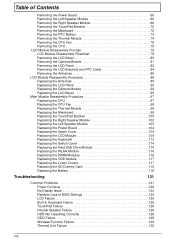
...GridVista (dual-display compatible 16 Hardware Specifications and Configurations 17 System Utilities 25 BIOS Setup Utility 25 Navigating the BIOS Utility 25 eMachines E627 BIOS 26 Information 26 Main 27 Security 28 Boot 31 Exit 32 BIOS Flash Utilities 33 DOS Flash Utility 34 WinFlash Utility 35...44 Removing the SD Dummy Card 45 Removing the Lower Covers 46 Removing the Optical Drive Module 47 Removing the DIMM Modules 49 Removing the WLAN Module 50 Removing the Hard Disk Drive Module 52 Main Unit Disassembly Process 54 Main Unit Disassembly Flowchart 54 Removing the ...
...GridVista (dual-display compatible 16 Hardware Specifications and Configurations 17 System Utilities 25 BIOS Setup Utility 25 Navigating the BIOS Utility 25 eMachines E627 BIOS 26 Information 26 Main 27 Security 28 Boot 31 Exit 32 BIOS Flash Utilities 33 DOS Flash Utility 34 WinFlash Utility 35...44 Removing the SD Dummy Card 45 Removing the Lower Covers 46 Removing the Optical Drive Module 47 Removing the DIMM Modules 49 Removing the WLAN Module 50 Removing the Hard Disk Drive Module 52 Main Unit Disassembly Process 54 Main Unit Disassembly Flowchart 54 Removing the ...
Service Guide
Page 8
... the Power Board 104 Replacing the Upper Cover 104 Replacing the LCD Module 108 Replacing the Keyboard 113 Replacing the Switch Cover 114 Replacing the Hard Disk Drive Module 114 Replacing the WLAN Module 116 Replacing the DIMM Modules 116 Replacing the ODD Module 117 Replacing the Lower Covers 117 Replacing the...
... the Power Board 104 Replacing the Upper Cover 104 Replacing the LCD Module 108 Replacing the Keyboard 113 Replacing the Switch Cover 114 Replacing the Hard Disk Drive Module 114 Replacing the WLAN Module 116 Replacing the DIMM Modules 116 Replacing the ODD Module 117 Replacing the Lower Covers 117 Replacing the...
Service Guide
Page 11
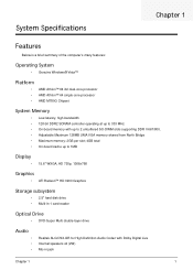
... Display • 15.6" WXGA, HD 720p, 1366x768 Graphics • ATI Radeon™ HD 3200 Graphics Storage subsystem • 2.5" hard disk drive • Multi-in-1 card-reader Optical Drive • DVD-Super Multi double-layer drive Audio • • • Realtek ALC272X-GR for High Definition Audio Codec with Dolby Digital Live Internal speakers x2...
... Display • 15.6" WXGA, HD 720p, 1366x768 Graphics • ATI Radeon™ HD 3200 Graphics Storage subsystem • 2.5" hard disk drive • Multi-in-1 card-reader Optical Drive • DVD-Super Multi double-layer drive Audio • • • Realtek ALC272X-GR for High Definition Audio Codec with Dolby Digital Live Internal speakers x2...

Service Guide
Page 16
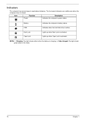
... Lights up when Caps Lock is charging. 2. Battery1 Indicates the computer's battery status. 1. Only one card can operate at any given time. Indicates when the hard disk drive is active.
... Lights up when Caps Lock is charging. 2. Battery1 Indicates the computer's battery status. 1. Only one card can operate at any given time. Indicates when the hard disk drive is active.
Service Guide
Page 20
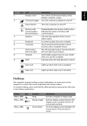
NOTE: 1. Battery HDD Num Lock Caps Lock Indicates the computer's battery status. Lights up when Num Lock is charging. 2. Indicates when the hard disk drive is activated. Charging: The light shows amber when the battery is activated. Fully charged: The light shows green when in AC mode. 10 Chapter 1 Lights up when Caps Lock is active. Indicators The computer has several easy-to-read status indicators. The front panel indicators are visible even when the computer cover is closed. Icon Function Power Description Indicates the computer's power status.
NOTE: 1. Battery HDD Num Lock Caps Lock Indicates the computer's battery status. Lights up when Num Lock is charging. 2. Indicates when the hard disk drive is activated. Charging: The light shows amber when the battery is activated. Fully charged: The light shows green when in AC mode. 10 Chapter 1 Lights up when Caps Lock is active. Indicators The computer has several easy-to-read status indicators. The front panel indicators are visible even when the computer cover is closed. Icon Function Power Description Indicates the computer's power status.
Service Guide
Page 29
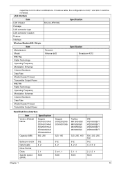
... Operating Frequency Modulation Schemes Channel Numbers Data Rate Media Access Protocol Transmitter Output Power Hard Disk Drive Interface Item Vendor & Model Name Capacity (MB) Specification Seagate ST9160310AS ST9160314AS ST9250315AS ST9320320AS ST9320325AS 500, ...250 Bytes per sector Data heads Drive Format Disks Spindle speed (RPM) 512 4, 2 2, 1 5400 Seagate ST9320320AS ST9160310AS Toshiba MK1655GSX MK1655GSX MK3255GSX MK3263GSX 320, 160 320, 250, ...
... Operating Frequency Modulation Schemes Channel Numbers Data Rate Media Access Protocol Transmitter Output Power Hard Disk Drive Interface Item Vendor & Model Name Capacity (MB) Specification Seagate ST9160310AS ST9160314AS ST9250315AS ST9320320AS ST9320325AS 500, ...250 Bytes per sector Data heads Drive Format Disks Spindle speed (RPM) 512 4, 2 2, 1 5400 Seagate ST9320320AS ST9160310AS Toshiba MK1655GSX MK1655GSX MK3255GSX MK3263GSX 320, 160 320, 250, ...
Service Guide
Page 37
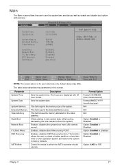
... startup to skip certain tests while booting, decreasing the time needed to factory defaults. The function allows the user to create a hidden partition on hard disc drive to store operation system and restore the system to boot the system. Sets the system date. This field shows the memory allocated for your reference...
... startup to skip certain tests while booting, decreasing the time needed to factory defaults. The function allows the user to create a hidden partition on hard disc drive to store operation system and restore the system to boot the system. Sets the system date. This field shows the memory allocated for your reference...
Service Guide
Page 41
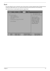
Select Boot Devices to select specific devices to escape the menu. Bootable devices includes the USB diskette drives, the onboard hard disk drive and the DVD drive in the module bay. F1 Help Esc Exit Select Item F5/F6 Change Values F9 Setup Defaults Select Menu Enter Select Sub-Menu F10 Save ...
Select Boot Devices to select specific devices to escape the menu. Bootable devices includes the USB diskette drives, the onboard hard disk drive and the DVD drive in the module bay. F1 Help Esc Exit Select Item F5/F6 Change Values F9 Setup Defaults Select Menu Enter Select Sub-Menu F10 Save ...

Service Guide
Page 62
Using the pull-tab, slide the HDD Module in the direction of the HDD bay. See "Removing the Lower Covers" on top of it. 52 Chapter 3 Lift the HDD Module clear of the arrow to device, avoid pressing down on it or placing heavy objects on page 46. 2. NOTE: To prevent damage to disconnect the interface. 3. Removing the Hard Disk Drive Module 1.
Using the pull-tab, slide the HDD Module in the direction of the HDD bay. See "Removing the Lower Covers" on top of it. 52 Chapter 3 Lift the HDD Module clear of the arrow to device, avoid pressing down on it or placing heavy objects on page 46. 2. NOTE: To prevent damage to disconnect the interface. 3. Removing the Hard Disk Drive Module 1.
Service Guide
Page 124
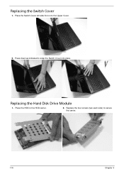
Replacing the Hard Disk Drive Module 1. Replacing the Switch Cover 1. Place the Switch Cover left side first on to secure the carrier. 114 Chapter 3 Replace the four screws (two each side) to the Upper Cover. 2. Place the HDD in the HDD carrier. 2. Press down as indicated to snap the Switch Cover into place.
Replacing the Hard Disk Drive Module 1. Replacing the Switch Cover 1. Place the Switch Cover left side first on to secure the carrier. 114 Chapter 3 Replace the four screws (two each side) to the Upper Cover. 2. Place the HDD in the HDD carrier. 2. Press down as indicated to snap the Switch Cover into place.
Service Guide
Page 144
... the problem remains, replace the following devices: • Non-Acer devices • Printer, mouse, and other external devices • Battery pack • Hard disk drive • DIMM • CD-ROM/Diskette drive Module • PC Cards 4. Do not replace a non-defective FRU: • System board • LCD assembly 134 Chapter 4 Power-off the...
... the problem remains, replace the following devices: • Non-Acer devices • Printer, mouse, and other external devices • Battery pack • Hard disk drive • DIMM • CD-ROM/Diskette drive Module • PC Cards 4. Do not replace a non-defective FRU: • System board • LCD assembly 134 Chapter 4 Power-off the...

Service Guide
Page 147
...Routine Description Initialize Extended BIOS Data Area Test and initialize PS/2 mouse Initialize floppy controller Determine number of ATA drives (optional) Initialize hard-disk controllers Initialize local-bus hard-disk controllers Jump to boot with INT 19 Initialize POST Error Manager (PEM) Initialize error logging Initialize error...Multi Processor table Search for option ROMs. One long, two short beeps on checksum failure Check for SMART Drive (optional) Shadow option ROMs Set up Power Management Initialize security engine (optional) Enable hardware interrupts Determine number of ATA and ...
...Routine Description Initialize Extended BIOS Data Area Test and initialize PS/2 mouse Initialize floppy controller Determine number of ATA drives (optional) Initialize hard-disk controllers Initialize local-bus hard-disk controllers Jump to boot with INT 19 Initialize POST Error Manager (PEM) Initialize error logging Initialize error...Multi Processor table Search for option ROMs. One long, two short beeps on checksum failure Check for SMART Drive (optional) Shadow option ROMs Set up Power Management Initialize security engine (optional) Enable hardware interrupts Determine number of ATA and ...
Service Guide
Page 189
... E EasyTouch Failure 132 Euro 15 External Module Disassembly Flowchart 43 F Features 1 Flash Utility 33 FPC Cable Removing 84 FRU (Field Replaceable Unit) List 145 H Hard Disk Drive Removing 52 Replacing 114 HDTV Switch Failure 133 Hibernation mode hotkey 14 Hot Keys 12 I Indicators 10 Intermittent Problems 134 Internal Speaker Failure 126 J Jumper...
... E EasyTouch Failure 132 Euro 15 External Module Disassembly Flowchart 43 F Features 1 Flash Utility 33 FPC Cable Removing 84 FRU (Field Replaceable Unit) List 145 H Hard Disk Drive Removing 52 Replacing 114 HDTV Switch Failure 133 Hibernation mode hotkey 14 Hot Keys 12 I Indicators 10 Intermittent Problems 134 Internal Speaker Failure 126 J Jumper...


