User Guide
Page 21
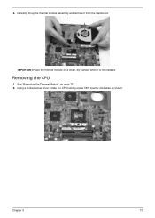
Removing the CPU 1. Using a slotted screw driver, rotate the CPU locking screw 180° counter-clockwise as shown. 4. Carefully lift up the thermal module assembly and remove it is not installed. Chapter 3 73 IMPORTANT:Place the thermal module on page 72. 2. See "Removing the Thermal Module" on a clean, dry surface when it from the mainboard.
Removing the CPU 1. Using a slotted screw driver, rotate the CPU locking screw 180° counter-clockwise as shown. 4. Carefully lift up the thermal module assembly and remove it is not installed. Chapter 3 73 IMPORTANT:Place the thermal module on page 72. 2. See "Removing the Thermal Module" on a clean, dry surface when it from the mainboard.
User Guide
Page 48
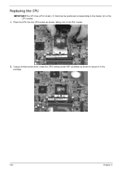
Replacing the CPU IMPORTANT:The CPU has a Pin1 locator (1) that must be positioned corresponding to secure it in the package. 100 Chapter 3 Place the CPU into the CPU socket as shown to the marker (2) on the CPU socket. 1. Using a slotted screw driver, rotate the CPU locking screw 180° clockwise as shown, taking note of the Pin1 locator. 1 2 2.
Replacing the CPU IMPORTANT:The CPU has a Pin1 locator (1) that must be positioned corresponding to secure it in the package. 100 Chapter 3 Place the CPU into the CPU socket as shown to the marker (2) on the CPU socket. 1. Using a slotted screw driver, rotate the CPU locking screw 180° clockwise as shown, taking note of the Pin1 locator. 1 2 2.


