eMachines Notebook User Guide (All Series)
Page 5
... type, UL listed/CSA certified, type SPT-2, rated 7 A 125 V minimum, VDE approved or its equivalent, 4.6 meters (15 feet) maximum length. Do not pierce, open or disassemble the battery. If the battery leaks and you need for safe battery usage This notebook uses a Lithium-ion battery. Unplug this product. • Use the...
... type, UL listed/CSA certified, type SPT-2, rated 7 A 125 V minimum, VDE approved or its equivalent, 4.6 meters (15 feet) maximum length. Do not pierce, open or disassemble the battery. If the battery leaks and you need for safe battery usage This notebook uses a Lithium-ion battery. Unplug this product. • Use the...
eMachines Notebook User Guide (All Series)
Page 6
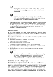
...negative (-) terminals of batteries according to keep the battery between 15°C and 25°C (59°F and 77°F). Do not disassemble or dispose of used batteries. vi contact with the leaked fluids, rinse thoroughly with a hot or cold battery may not work temporarily, ...of a new battery is fully charged. Follow local regulations when disposing of them away from the battery, which came bundled with eMachines approved chargers designated for its intended purpose. The capacity and lifetime of another battery may explode. Battery performance is especially limited in...
...negative (-) terminals of batteries according to keep the battery between 15°C and 25°C (59°F and 77°F). Do not disassemble or dispose of used batteries. vi contact with the leaked fluids, rinse thoroughly with a hot or cold battery may not work temporarily, ...of a new battery is fully charged. Follow local regulations when disposing of them away from the battery, which came bundled with eMachines approved chargers designated for its intended purpose. The capacity and lifetime of another battery may explode. Battery performance is especially limited in...
Service Guide
Page 37
... Replacement This chapter contains step-by-step procedures on how to avoid mismatch when putting back the components. Disassembly Requirements To disassemble the computer, you need the following tools: • Wrist grounding strap and conductive mat for preventing electrostatic discharge • Flat screwdriver • Philips screwdriver • ...
... Replacement This chapter contains step-by-step procedures on how to avoid mismatch when putting back the components. Disassembly Requirements To disassemble the computer, you need the following tools: • Wrist grounding strap and conductive mat for preventing electrostatic discharge • Flat screwdriver • Philips screwdriver • ...
Service Guide
Page 38
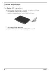
Remove the battery pack. See "Removing the Battery Pack" on a flat, stable surface. 4. Turn off the power to the system and all power and signal cables from the system. 3. Place the system on page 51. 48 Chapter 3 Unplug the AC adapter and all peripherals. 2. General Information Pre-disassembly Instructions Before proceeding with the disassembly procedure, make sure that you do the following: 1.
Remove the battery pack. See "Removing the Battery Pack" on a flat, stable surface. 4. Turn off the power to the system and all power and signal cables from the system. 3. Place the system on page 51. 48 Chapter 3 Unplug the AC adapter and all peripherals. 2. General Information Pre-disassembly Instructions Before proceeding with the disassembly procedure, make sure that you do the following: 1.

Service Guide
Page 39
.... Observe the order of the sequence to avoid damage to remove the mainboard, you must first remove the keyboard, then disassemble the inside assembly frame in the succeeding disassembly sections illustrate the entire disassembly sequence. Main Screw List Item A B C D E F G H I Screw M2 x L4 M2 x L18 M2 x L3 M3 x L4 M2.5 x L6 M2 x L2.5 M2...
.... Observe the order of the sequence to avoid damage to remove the mainboard, you must first remove the keyboard, then disassemble the inside assembly frame in the succeeding disassembly sections illustrate the entire disassembly sequence. Main Screw List Item A B C D E F G H I Screw M2 x L4 M2 x L18 M2 x L3 M3 x L4 M2.5 x L6 M2 x L2.5 M2...
Service Guide
Page 40
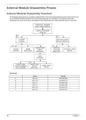
For example, if you must first remove the keyboard, then disassemble the inside assembly frame in that order. External Module Disassembly Process External Modules Disassembly Flowchart The flowchart below gives you a graphic representation on the entire disassembly sequence and instructs you on the components that need to remove the mainboard, you want to be removed...
For example, if you must first remove the keyboard, then disassemble the inside assembly frame in that order. External Module Disassembly Process External Modules Disassembly Flowchart The flowchart below gives you a graphic representation on the entire disassembly sequence and instructs you on the components that need to remove the mainboard, you want to be removed...
Service Guide
Page 48
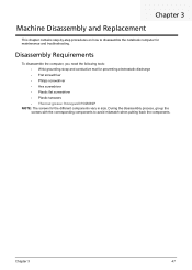
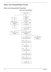
Main Unit Disassembly Process Main Unit Disassembly Flowchart MAIN UNIT DISASSEMBLY MAIN UNIT Hx2 FAN Ax5 CPU HEATSINK MODULE CPU Gx1 LED INDICATORS BOARD MIDDLE COVER Cx2 KEYBOARD Ex4 LCD MODULE Ax1, Ex11 UPPER CASE Cx4 TOUCHPAD BRACKET ASSEMBLY TOUCHPAD BOARD Cx2 DAUGHTER BOARD Ax1 MAINBOARD Cx2 MODEM BOARD Cx2 FINGERPRINT BOARD BLUETOOTH BOARD Dx2 SPEAKER MODULES LOWER CASE 58 Chapter 3
Main Unit Disassembly Process Main Unit Disassembly Flowchart MAIN UNIT DISASSEMBLY MAIN UNIT Hx2 FAN Ax5 CPU HEATSINK MODULE CPU Gx1 LED INDICATORS BOARD MIDDLE COVER Cx2 KEYBOARD Ex4 LCD MODULE Ax1, Ex11 UPPER CASE Cx4 TOUCHPAD BRACKET ASSEMBLY TOUCHPAD BOARD Cx2 DAUGHTER BOARD Ax1 MAINBOARD Cx2 MODEM BOARD Cx2 FINGERPRINT BOARD BLUETOOTH BOARD Dx2 SPEAKER MODULES LOWER CASE 58 Chapter 3

Service Guide
Page 66
LCD Module Disassembly Process LCD Module Disassembly Flowchart LCD MODULE DISASSEMBLY LCD MODULE Ex2, Hx4 LCD BEZEL Hx1 INVERTER BOARD CCD BOARD LCD ASSEMBLY LCD FPC CABLE Ix2 Cx4 LEFT LCD BRACKET Cx4 RIGHT LCD BRACKET Ix1 LEFT HINGE Ix1 RIGHT HINGE MICROPHONE MAIN ANTENNA AUXILIARY ANTENNA Main Screw List Item C E H I LCD BACK PANEL Screw M2 x L3 M2.5 x L6 M2.5 x L5 M2.5 x L5 Part No. 86.9A552.3R0 86.00E33.736 86.00F87.735 86.00F00.735 76 Chapter 3
LCD Module Disassembly Process LCD Module Disassembly Flowchart LCD MODULE DISASSEMBLY LCD MODULE Ex2, Hx4 LCD BEZEL Hx1 INVERTER BOARD CCD BOARD LCD ASSEMBLY LCD FPC CABLE Ix2 Cx4 LEFT LCD BRACKET Cx4 RIGHT LCD BRACKET Ix1 LEFT HINGE Ix1 RIGHT HINGE MICROPHONE MAIN ANTENNA AUXILIARY ANTENNA Main Screw List Item C E H I LCD BACK PANEL Screw M2 x L3 M2.5 x L6 M2.5 x L5 M2.5 x L5 Part No. 86.9A552.3R0 86.00E33.736 86.00F87.735 86.00F00.735 76 Chapter 3
Service Guide
Page 77
...; All components appear normal. Verify the symptoms by attempting to test only Acer products. Chapter 4 87 If any power sources when performing an assembly or disassembly procedures. 4.
...; All components appear normal. Verify the symptoms by attempting to test only Acer products. Chapter 4 87 If any power sources when performing an assembly or disassembly procedures. 4.


