
User Guide
Page 3
... and product certifications. GS1510 Series User's Guide 3 Related Documentation • Supporting Disc Refer to the included CD for support documents. • ZyXEL Web Site Please refer to : techwriters@zyxel.com.tw Thank you! You should have at www.zyxel.com. Documentation Feedback Send... your comments, questions or suggestions to www.zyxel.com for people who want to configure the Switch using the Web Configurator...
... and product certifications. GS1510 Series User's Guide 3 Related Documentation • Supporting Disc Refer to the included CD for support documents. • ZyXEL Web Site Please refer to : techwriters@zyxel.com.tw Thank you! You should have at www.zyxel.com. Documentation Feedback Send... your comments, questions or suggestions to www.zyxel.com for people who want to configure the Switch using the Web Configurator...
User Guide
Page 5
...Switch", the "device", or the "system" in the navigation panel, then the Log sub menu and finally the Log Setting tab to get to use one or more characters and then press the [ENTER] key. Note: Notes tell you other important information (for example, other words". Syntax Conventions • The GS1510-16/GS1510-24... may be referred to configure or helpful tips) or recommendations. GS1510 Series User's Guide 5
...Switch", the "device", or the "system" in the navigation panel, then the Log sub menu and finally the Log Setting tab to get to use one or more characters and then press the [ENTER] key. Note: Notes tell you other important information (for example, other words". Syntax Conventions • The GS1510-16/GS1510-24... may be referred to configure or helpful tips) or recommendations. GS1510 Series User's Guide 5
User Guide
Page 6
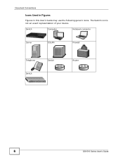
Switch Computer Notebook computer Server DSLAM Firewall Telephone Switch Switch Router 6 GS1510 Series User's Guide Document Conventions Icons Used in Figures Figures in this User's Guide may use the following generic icons. The Switch icon is not an exact representation of your device.
Switch Computer Notebook computer Server DSLAM Firewall Telephone Switch Switch Router 6 GS1510 Series User's Guide Document Conventions Icons Used in Figures Figures in this User's Guide may use the following generic icons. The Switch icon is not an exact representation of your device.

User Guide
Page 9
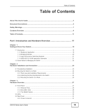
Contents Overview Contents Overview Introduction and Hardware Overview 17 Getting to Know Your Switch ...19 Hardware Installation and Connection 23 Hardware Overview ...27 Basic Settings ...33 The Web Configurator ...35 System ...45 General Settings ...47 MAC Management ...51 Port ....1x ...117 Web Authentication ...123 Maintenance ...129 SNMP ...135 User Account ...143 Troubleshooting & Product Specifications 145 Troubleshooting ...147 Product Specifications ...151 Appendices and Index ...157 GS1510 Series User's Guide 9
Contents Overview Contents Overview Introduction and Hardware Overview 17 Getting to Know Your Switch ...19 Hardware Installation and Connection 23 Hardware Overview ...27 Basic Settings ...33 The Web Configurator ...35 System ...45 General Settings ...47 MAC Management ...51 Port ....1x ...117 Web Authentication ...123 Maintenance ...129 SNMP ...135 User Account ...143 Troubleshooting & Product Specifications 145 Troubleshooting ...147 Product Specifications ...151 Appendices and Index ...157 GS1510 Series User's Guide 9
User Guide
Page 11
... ...23 2.2 Mounting the Switch on a Rack 24 2.2.1 Rack-mounted Installation Requirements 24 2.2.2 Attaching the Mounting Brackets to the Switch 24 2.2.3 Mounting the Switch on a Rack 25 Chapter 3 Hardware Overview...27 3.1 Front Panel ...27 3.1.1 Ethernet Ports ...28 3.1.2 Mini-GBIC Slots ...28 3.1.3 The RESET Button ...30 3.2 LEDs ...30 3.3 Rear Panel ...31 3.3.1 Power Connector ...31 GS1510 Series User's Guide 11
... ...23 2.2 Mounting the Switch on a Rack 24 2.2.1 Rack-mounted Installation Requirements 24 2.2.2 Attaching the Mounting Brackets to the Switch 24 2.2.3 Mounting the Switch on a Rack 25 Chapter 3 Hardware Overview...27 3.1 Front Panel ...27 3.1.1 Ethernet Ports ...28 3.1.2 Mini-GBIC Slots ...28 3.1.3 The RESET Button ...30 3.2 LEDs ...30 3.3 Rear Panel ...31 3.3.1 Power Connector ...31 GS1510 Series User's Guide 11
User Guide
Page 12
... 4.3 System Login ...35 4.3.1 Smart Mode ...36 4.3.2 The Advanced Main Screen 40 4.3.3 The Navigation Panel 40 4.3.4 Change Your Password 42 4.4 Saving Your Configuration 43 4.5 Switch Lockout ...43 4.6 Resetting the Switch ...43 4.7 Logging Out of the Web Configurator 44 Chapter 5 System ...45 5.1 System Screen ...45 Chapter 6 General Settings ...47 6.1 What You Can Do ...47...MAC Settings ...52 7.5 MAC Table ...53 Chapter 8 Port Mirroring ...55 8.1 Port Mirroring Settings ...55 Chapter 9 Port Settings...57 9.1 Port Settings ...57 9.1.1 Auto Negotiation ...57 12 GS1510 Series User's Guide
... 4.3 System Login ...35 4.3.1 Smart Mode ...36 4.3.2 The Advanced Main Screen 40 4.3.3 The Navigation Panel 40 4.3.4 Change Your Password 42 4.4 Saving Your Configuration 43 4.5 Switch Lockout ...43 4.6 Resetting the Switch ...43 4.7 Logging Out of the Web Configurator 44 Chapter 5 System ...45 5.1 System Screen ...45 Chapter 6 General Settings ...47 6.1 What You Can Do ...47...MAC Settings ...52 7.5 MAC Table ...53 Chapter 8 Port Mirroring ...55 8.1 Port Mirroring Settings ...55 Chapter 9 Port Settings...57 9.1 Port Settings ...57 9.1.1 Auto Negotiation ...57 12 GS1510 Series User's Guide
User Guide
Page 16
... 145 Chapter 24 Troubleshooting...147 24.1 Power, Hardware Connections, and LEDs 147 24.2 Switch Access and Login 148 Chapter 25 Product Specifications ...151 25.1 General Switch Specifications 151 Part... VI: Appendices and Index 157 Appendix A Device Auto Discovery 159 Appendix B IP Addresses and Subnetting 165 Appendix C Legal Information 175 Appendix D Open Software Announcements 179 Index...199 16 GS1510...
... 145 Chapter 24 Troubleshooting...147 24.1 Power, Hardware Connections, and LEDs 147 24.2 Switch Access and Login 148 Chapter 25 Product Specifications ...151 25.1 General Switch Specifications 151 Part... VI: Appendices and Index 157 Appendix A Device Auto Discovery 159 Appendix B IP Addresses and Subnetting 165 Appendix C Legal Information 175 Appendix D Open Software Announcements 179 Index...199 16 GS1510...

User Guide
Page 17
PART I Introduction and Hardware Overview Getting to Know Your Switch (19) Hardware Installation and Connection (23) Hardware Overview (27) 17
PART I Introduction and Hardware Overview Getting to Know Your Switch (19) Hardware Installation and Connection (23) Hardware Overview (27) 17
User Guide
Page 19
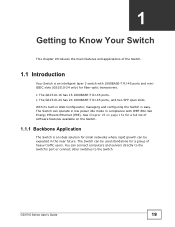
... operate in low power idle mode in Web Configurator, managing and configuring the Switch is easy. With its built-in compliance with 1000BASE-T RJ-45 ports and miniGBIC slots (GS1510-24 only) for a group of the Switch. 1.1 Introduction Your Switch is an ideal solution for small networks where rapid growth can be used standalone for...
... operate in low power idle mode in Web Configurator, managing and configuring the Switch is easy. With its built-in compliance with 1000BASE-T RJ-45 ports and miniGBIC slots (GS1510-24 only) for a group of the Switch. 1.1 Introduction Your Switch is an ideal solution for small networks where rapid growth can be used standalone for...
User Guide
Page 20
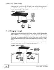
... using a Gigabit Ethernet/mini-GBIC port on the server. To expand the network, simply add more networking devices such as switches, routers, computers, print servers etc. Figure 2 Bridging Application 20 GS1510 Series User's Guide All users that need high bandwidth can alleviate bandwidth contention and eliminate server and network bottlenecks. Figure 1 Backbone...
... using a Gigabit Ethernet/mini-GBIC port on the server. To expand the network, simply add more networking devices such as switches, routers, computers, print servers etc. Figure 2 Bridging Application 20 GS1510 Series User's Guide All users that need high bandwidth can alleviate bandwidth contention and eliminate server and network bottlenecks. Figure 1 Backbone...
User Guide
Page 21
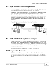
...use trunking to connect these two networks. With VLAN, a station cannot directly talk to or hear from stations that need high bandwidth. GS1510 Series User's Guide 21 A station can provide the same bandwidth as ATM (Asynchronous Transmission Mode) is ideal for most people due to... the expense of replacing all ports can be partitioned into multiple logical networks. Chapter 1 Getting to Know Your Switch 1.1.3 High Performance Switching Example The Switch is not feasible for connecting two networks that are not in the same VLAN group share the same frame broadcast domain...
...use trunking to connect these two networks. With VLAN, a station cannot directly talk to or hear from stations that need high bandwidth. GS1510 Series User's Guide 21 A station can provide the same bandwidth as ATM (Asynchronous Transmission Mode) is ideal for most people due to... the expense of replacing all ports can be partitioned into multiple logical networks. Chapter 1 Getting to Know Your Switch 1.1.3 High Performance Switching Example The Switch is not feasible for connecting two networks that are not in the same VLAN group share the same frame broadcast domain...
User Guide
Page 22
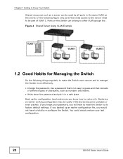
... letters. • Write down the password and put it ). Ports on the Switch can be useful if the device becomes unstable or even crashes. If you forget your last configuration. 22 GS1510 Series User's Guide Restoring an earlier working configuration may be used by all ports in... a safe place. If you backed up the configuration (and make the Switch more effectively. • Change the password. Chapter 1 Getting...
... letters. • Write down the password and put it ). Ports on the Switch can be useful if the device becomes unstable or even crashes. If you forget your last configuration. 22 GS1510 Series User's Guide Restoring an earlier working configuration may be used by all ports in... a safe place. If you backed up the configuration (and make the Switch more effectively. • Change the password. Chapter 1 Getting...
User Guide
Page 23
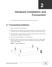
Figure 5 Attaching Rubber Feet GS1510 Series User's Guide 23 These rubber feet help protect the Switch from the rubber feet. 5 Attach the rubber feet to each corner on a smooth, level surface strong enough to allow air circulation and the attachment of ... or vibration and ensure space between devices when stacking. Make sure there is a power outlet nearby. 3 Make sure there is clean and dry. 2 Set the Switch on the bottom of the Switch and the connected cables. CHAPTER 2 Hardware Installation and Connection This chapter shows you how to install and connect the...
Figure 5 Attaching Rubber Feet GS1510 Series User's Guide 23 These rubber feet help protect the Switch from the rubber feet. 5 Attach the rubber feet to each corner on a smooth, level surface strong enough to allow air circulation and the attachment of ... or vibration and ensure space between devices when stacking. Make sure there is a power outlet nearby. 3 Make sure there is clean and dry. 2 Set the Switch on the bottom of the Switch and the connected cables. CHAPTER 2 Hardware Installation and Connection This chapter shows you how to install and connect the...
User Guide
Page 24
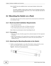
... head screws and a #2 Philips screwdriver. This is especially important for enclosed rack installations. 2.2 Mounting the Switch on the side of the Switch. Figure 6 Attaching the Mounting Brackets 24 GS1510 Series User's Guide Take all the equipment it contains. • Make sure the position of the... Switch. Chapter 2 Hardware Installation and Connection Note: Do NOT block the ventilation holes. For proper ...
... head screws and a #2 Philips screwdriver. This is especially important for enclosed rack installations. 2.2 Mounting the Switch on the side of the Switch. Figure 6 Attaching the Mounting Brackets 24 GS1510 Series User's Guide Take all the equipment it contains. • Make sure the position of the... Switch. Chapter 2 Hardware Installation and Connection Note: Do NOT block the ventilation holes. For proper ...
User Guide
Page 25
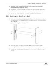
..., install the M3 flat head screws through the mounting bracket holes into the Switch. 3 Repeat steps 1 and 2 to the Switch) on one side of the rack. GS1510 Series User's Guide 25 Proceed to the next section. 2.2.3 Mounting the Switch on a Rack 1 Position a mounting bracket (that is already attached to ... on the other side of the rack, lining up the two screw holes on the bracket with the screw holes on a rack. Figure 7 Mounting the Switch on a Rack 2 Using a #2 Philips screwdriver, install the M5 flat head screws through the mounting bracket holes into the rack. 3 Repeat steps 1 ...
..., install the M3 flat head screws through the mounting bracket holes into the Switch. 3 Repeat steps 1 and 2 to the Switch) on one side of the rack. GS1510 Series User's Guide 25 Proceed to the next section. 2.2.3 Mounting the Switch on a Rack 1 Position a mounting bracket (that is already attached to ... on the other side of the rack, lining up the two screw holes on the bracket with the screw holes on a rack. Figure 7 Mounting the Switch on a Rack 2 Using a #2 Philips screwdriver, install the M5 flat head screws through the mounting bracket holes into the rack. 3 Repeat steps 1 ...
User Guide
Page 27
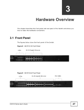
CHAPTER 3 Hardware Overview This chapter describes the front panel and rear panel of the Switch and shows you how to make the hardware connections. 3.1 Front Panel The figures below show the front panel of the Switch. Figure 8 GS1510-16 Front Panel LEDs RJ-45 Gigabit Ethernet Figure 9 GS1510-24 Front Panel LEDs RJ-45 Gigabit Ethernet Mini-GBIC GS1510 Series User's Guide 27
CHAPTER 3 Hardware Overview This chapter describes the front panel and rear panel of the Switch and shows you how to make the hardware connections. 3.1 Front Panel The figures below show the front panel of the Switch. Figure 8 GS1510-16 Front Panel LEDs RJ-45 Gigabit Ethernet Figure 9 GS1510-24 Front Panel LEDs RJ-45 Gigabit Ethernet Mini-GBIC GS1510 Series User's Guide 27
User Guide
Page 28
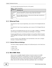
...with transceivers. See the SFF committee's INF-8074i specification Rev 1.0 for fiber-optic connections to daisy-chain other switches. Ports Mini-GBIC Slots (GS1510-24 only) Use mini-GBIC transceivers in these Gigabit Ethernet ports to the optimum Ethernet speed (100/1000Mpbs) and duplex...houses a transmitter and a receiver. You must use them to backbone Ethernet switches. 3.1.1 Ethernet Ports The GS1510-16 has 16 auto-negotiating, auto-crossover RJ-45 Gigabit Ethernet ports. The GS1510-24 has 24 auto-negotiating, auto-crossover RJ-45 Gigabit Ethernet ports. Chapter 3 Hardware ...
...with transceivers. See the SFF committee's INF-8074i specification Rev 1.0 for fiber-optic connections to daisy-chain other switches. Ports Mini-GBIC Slots (GS1510-24 only) Use mini-GBIC transceivers in these Gigabit Ethernet ports to the optimum Ethernet speed (100/1000Mpbs) and duplex...houses a transmitter and a receiver. You must use them to backbone Ethernet switches. 3.1.1 Ethernet Ports The GS1510-16 has 16 auto-negotiating, auto-crossover RJ-45 Gigabit Ethernet ports. The GS1510-24 has 24 auto-negotiating, auto-crossover RJ-45 Gigabit Ethernet ports. Chapter 3 Hardware ...
User Guide
Page 29
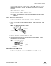
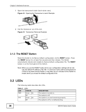
... Transceiver Installation Example 2 Press the transceiver firmly until it is operating. GS1510 Series User's Guide 29 Chapter 3 Hardware Overview You can use different transceivers to connect to Ethernet switches with the exposed section of PCB board facing down. Check the LEDs to... Use the following steps to install a mini GBIC transceiver (SFP module). 1 Insert the transceiver into place. 3 The Switch automatically detects the installed transceiver. Figure 11 Installed Transceiver 3.1.2.2 Transceiver Removal Use the following steps to remove a mini GBIC transceiver (SFP module)....
... Transceiver Installation Example 2 Press the transceiver firmly until it is operating. GS1510 Series User's Guide 29 Chapter 3 Hardware Overview You can use different transceivers to connect to Ethernet switches with the exposed section of PCB board facing down. Check the LEDs to... Use the following steps to install a mini GBIC transceiver (SFP module). 1 Insert the transceiver into place. 3 The Switch automatically detects the installed transceiver. Figure 11 Installed Transceiver 3.1.2.2 Transceiver Removal Use the following steps to remove a mini GBIC transceiver (SFP module)....
User Guide
Page 30
...168.1.1) and user name (admin) and password (1234) to its factory default configuration file. The system is on the front panel of the Switch. The Switch automatically reboots and reloads its factory default configuration via the RESET button. It may take up to 2 minutes for at least five seconds and... On Off SYS Green On Off DESCRIPTION The system is off or is malfunctioning. 30 GS1510 Series User's Guide The system is turned on and functioning properly. Press the RESET button for the Switch to restart when you use the RESET button all of the slot. Note: When you...
...168.1.1) and user name (admin) and password (1234) to its factory default configuration file. The system is on the front panel of the Switch. The Switch automatically reboots and reloads its factory default configuration via the RESET button. It may take up to 2 minutes for at least five seconds and... On Off SYS Green On Off DESCRIPTION The system is off or is malfunctioning. 30 GS1510 Series User's Guide The system is turned on and functioning properly. Press the RESET button for the Switch to restart when you use the RESET button all of the slot. Note: When you...
User Guide
Page 31
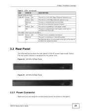
... power cord. Mini-GBIC Slots (GS1510-24 ONLY) LNK/ACT Green On The port has a successful connection. Figure 14 GS1510-16 Rear Panel Figure 15 GS1510-24 Rear Panel 3.3.1 Power Connector Make sure you are occurring. GS1510 Series User's Guide 31 Blinking The... port is transmitting/receiving data. Amber On The link to a 100 Mbps Ethernet network is down . 3.3 Rear Panel The following figures show the rear panels of the AC power input model Switch...
... power cord. Mini-GBIC Slots (GS1510-24 ONLY) LNK/ACT Green On The port has a successful connection. Figure 14 GS1510-16 Rear Panel Figure 15 GS1510-24 Rear Panel 3.3.1 Power Connector Make sure you are occurring. GS1510 Series User's Guide 31 Blinking The... port is transmitting/receiving data. Amber On The link to a 100 Mbps Ethernet network is down . 3.3 Rear Panel The following figures show the rear panels of the AC power input model Switch...
