

User Guide
Page 3
... 2 Hardware Description and Connection 9 2.1 Rear Panel ...9 2.1.1 Rear Panel Power Connection 9 2.2 Front Panel ...9 2.2.1 RJ-45 Auto-negotiating Ports 10 2.2.2 IEEE 802.3az EEE ...10 2.2.3 SFP Slots (GS1100-24 Only 10 2.2.4 Front Panel Connections ...12 2.2.5 Front Panel LEDs ...12 2.3 Hardware Installation ...14 2.3.1 Wall Mounting ...14 2.3.2 Rack Mounting ...15 2.3.3 Mounting the Switch on a Rack...
... 2 Hardware Description and Connection 9 2.1 Rear Panel ...9 2.1.1 Rear Panel Power Connection 9 2.2 Front Panel ...9 2.2.1 RJ-45 Auto-negotiating Ports 10 2.2.2 IEEE 802.3az EEE ...10 2.2.3 SFP Slots (GS1100-24 Only 10 2.2.4 Front Panel Connections ...12 2.2.5 Front Panel LEDs ...12 2.3 Hardware Installation ...14 2.3.1 Wall Mounting ...14 2.3.2 Rack Mounting ...15 2.3.3 Mounting the Switch on a Rack...

User Guide
Page 5
...). The Switch is a 10/100/1000 Mbps multi-port switch that offers low latency for uplink connection. Table 1 GS1100 Series Comparison Table PORT/SWITCH DETAILS GS1100-8HP GS1100-16 8 10/100/1000Base-T Ethernet ports (including 4 PoE ports) 16 10/100/1000Base-T Ethernet ports 24 10/100/1000Base-T Ethernet ports 2 100/1000Base-X SFP slots One physical IEEE...
...). The Switch is a 10/100/1000 Mbps multi-port switch that offers low latency for uplink connection. Table 1 GS1100 Series Comparison Table PORT/SWITCH DETAILS GS1100-8HP GS1100-16 8 10/100/1000Base-T Ethernet ports (including 4 PoE ports) 16 10/100/1000Base-T Ethernet ports 24 10/100/1000Base-T Ethernet ports 2 100/1000Base-X SFP slots One physical IEEE...

User Guide
Page 6
...Supports automatic address learning. • Supports IEEE 802.3az EEE • Supports IEEE 802.3af and IEEE 802.3at PoE standards (only GS1100-8HP) • Full wire speed forwarding rate. • Supports 802.1p CoS. • Embedded 8K MAC address table providing 8000 MAC ...1.3 Applications This section provides two network topology examples in which the Switch is used. 6 GS1100 Series User's Guide Chapter 1 Getting to Know Your Switch Figure 1 Front Panel GS1100-8HP GS1100-16 GS1100-24 GS1100-24E 1.2 Features The following are the essential features of the Switch. • Conforms to...
...Supports automatic address learning. • Supports IEEE 802.3az EEE • Supports IEEE 802.3af and IEEE 802.3at PoE standards (only GS1100-8HP) • Full wire speed forwarding rate. • Supports 802.1p CoS. • Embedded 8K MAC address table providing 8000 MAC ...1.3 Applications This section provides two network topology examples in which the Switch is used. 6 GS1100 Series User's Guide Chapter 1 Getting to Know Your Switch Figure 1 Front Panel GS1100-8HP GS1100-16 GS1100-24 GS1100-24E 1.2 Features The following are the essential features of the Switch. • Conforms to...

User Guide
Page 9
... to the power receptacle on the back of the Switch and the other end to the power supply requirements on the panel. GS1100 Series User's Guide 9 For the GS1100-8HP, GS1100-16 and GS1100-24E, use the POWER ON/OFF switch to have the Switch power on the rear panel of the Switch. CHAPTER 2 Hardware Description...
... to the power receptacle on the back of the Switch and the other end to the power supply requirements on the panel. GS1100 Series User's Guide 9 For the GS1100-8HP, GS1100-16 and GS1100-24E, use the POWER ON/OFF switch to have the Switch power on the rear panel of the Switch. CHAPTER 2 Hardware Description...

User Guide
Page 13
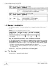
Figure 11 Front Panel LEDs GS1100-8HP GS1100-16 GS1100-24 GS1100-24E Chapter 2 Hardware Description and Connection The following table describes the LEDs. Off ... port. Blinking The port is not receiving power. Off Power supplied to an Ethernet network at 1000M speed. GS1100 Series User's Guide 13 PoE MAX Red On Power supplied to the PoE port(s) reachs the power budget limit... receiving or transmitting data at 1000M speed. Table 3 The Front Panel LED Descriptions: GS1100-8HP LED COLOR STATUS DESCRIPTION PWR Green On The Switch is below the power budget limit.
Figure 11 Front Panel LEDs GS1100-8HP GS1100-16 GS1100-24 GS1100-24E Chapter 2 Hardware Description and Connection The following table describes the LEDs. Off ... port. Blinking The port is not receiving power. Off Power supplied to an Ethernet network at 1000M speed. GS1100 Series User's Guide 13 PoE MAX Red On Power supplied to the PoE port(s) reachs the power budget limit... receiving or transmitting data at 1000M speed. Table 3 The Front Panel LED Descriptions: GS1100-8HP LED COLOR STATUS DESCRIPTION PWR Green On The Switch is below the power budget limit.
User Guide
Page 14
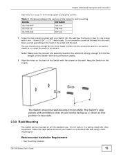
... to support the weight of each GS1100 model: Table 5 GS1100 Series Installation Comparison Table MODEL FEATURE Desktop Device Wall-mountable Rack-mountable GS1100-8HP GS1100-16 GS1100-24 GS1100-24E Note: Ask an authorized technician to attach the Switch to the rack/wall. For GS1100-16, GS1100-24 and GS110-24E, the size... on top of your Switch to an Ethernet network at 10M or 100M speed. Off The port is suitable for instruction. For GS1100-8HP, GS1100-16 and GS110-24E, you can place the Switch directly on page 15 for rackmounting and you can refer to an Ethernet network....
... to support the weight of each GS1100 model: Table 5 GS1100 Series Installation Comparison Table MODEL FEATURE Desktop Device Wall-mountable Rack-mountable GS1100-8HP GS1100-16 GS1100-24 GS1100-24E Note: Ask an authorized technician to attach the Switch to the rack/wall. For GS1100-16, GS1100-24 and GS110-24E, the size... on top of your Switch to an Ethernet network at 10M or 100M speed. Off The port is suitable for instruction. For GS1100-8HP, GS1100-16 and GS110-24E, you can place the Switch directly on page 15 for rackmounting and you can refer to an Ethernet network....
User Guide
Page 15
... to place the screws. leave a small gap between the centers of the Switch. Hang the Switch on page 15 for wall mounting MODEL GS1100-8HP GS1100-16 DISTANCE 120 mm 148 mm GS1100-24E 207 mm 1 Screw the two screws provided with 6 mm ~ 8 mm (0.24" ~ 0.31") wide heads. Chapter 2 Hardware Description and Connection See Table...
... to place the screws. leave a small gap between the centers of the Switch. Hang the Switch on page 15 for wall mounting MODEL GS1100-8HP GS1100-16 DISTANCE 120 mm 148 mm GS1100-24E 207 mm 1 Screw the two screws provided with 6 mm ~ 8 mm (0.24" ~ 0.31") wide heads. Chapter 2 Hardware Description and Connection See Table...

User Guide
Page 16
Figure 12 Attaching the Mounting Brackets (GS1100-16 and GS1100-24E) Figure 13 Attaching the Mounting Brackets (GS1100-24) 2 Using a #2 Philips screwdriver, install the M3 flat head screws through the mounting bracket holes into the Switch. 3 Repeat steps 1 and 2 to ... Proceed to the next section. 2.3.3 Mounting the Switch on a rack. Take all the equipment it contains. • Make sure the position of the rack. 16 GS1100 Series User's Guide Chapter 2 Hardware Description and Connection • Eight M3 flat head screws and a #2 Philips screwdriver. • Four M5 flat head screws and...
Figure 12 Attaching the Mounting Brackets (GS1100-16 and GS1100-24E) Figure 13 Attaching the Mounting Brackets (GS1100-24) 2 Using a #2 Philips screwdriver, install the M3 flat head screws through the mounting bracket holes into the Switch. 3 Repeat steps 1 and 2 to ... Proceed to the next section. 2.3.3 Mounting the Switch on a rack. Take all the equipment it contains. • Make sure the position of the rack. 16 GS1100 Series User's Guide Chapter 2 Hardware Description and Connection • Eight M3 flat head screws and a #2 Philips screwdriver. • Four M5 flat head screws and...

User Guide
Page 17
Chapter 2 Hardware Description and Connection Figure 14 Mounting the Switch on a Rack (GS1100-16 and GS1100-24E) Figure 15 Mounting the Switch on a Rack (GS1100-24) 2 Using a #2 Philips screwdriver, install the M5 flat head screws through the mounting bracket holes into the rack. 3 Repeat steps 1 and 2 to attach the second mounting bracket on the other side of the rack. GS1100 Series User's Guide 17
Chapter 2 Hardware Description and Connection Figure 14 Mounting the Switch on a Rack (GS1100-16 and GS1100-24E) Figure 15 Mounting the Switch on a Rack (GS1100-24) 2 Using a #2 Philips screwdriver, install the M5 flat head screws through the mounting bracket holes into the rack. 3 Repeat steps 1 and 2 to attach the second mounting bracket on the other side of the rack. GS1100 Series User's Guide 17
User Guide
Page 20
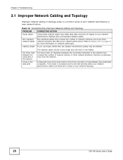
Figure 16 Troubleshooting Improper Network Cabling and Topology PROBLEM Faulty cables Non-standard network cables Cabling Length CORRECTIVE ACTION Using faulty network cables may affect data rates ... network performance. If you use longer cables than one path or route between the connected computers in broadcast storms that affect your network topology. 20 GS1100 Series User's Guide
Figure 16 Troubleshooting Improper Network Cabling and Topology PROBLEM Faulty cables Non-standard network cables Cabling Length CORRECTIVE ACTION Using faulty network cables may affect data rates ... network performance. If you use longer cables than one path or route between the connected computers in broadcast storms that affect your network topology. 20 GS1100 Series User's Guide

User Guide
Page 23
... 21 D Data path loop 20 disclaimer 21 E EEE 5, 10 Energy Efficient Ethernet 10 F Faulty cables 20 FCC interference statement 21 Front Panel 9 GS1100 Series User's Guide Index Index Front Panel Connections 12 H High Power over Ethernet 8 I IEEE 802.3at 8 IEEE 802.3az 10 installation precautions... 16 transceivers 10 L LED Descriptions LK/ACT 14 PWR 13, 14 Low Power Idle 10 LPI signal 10 M mounting brackets 16 N network cable crossover 12 straight-through 12 Network Cable Types 12 Non-standard network cables 20...
... 21 D Data path loop 20 disclaimer 21 E EEE 5, 10 Energy Efficient Ethernet 10 F Faulty cables 20 FCC interference statement 21 Front Panel 9 GS1100 Series User's Guide Index Index Front Panel Connections 12 H High Power over Ethernet 8 I IEEE 802.3at 8 IEEE 802.3az 10 installation precautions... 16 transceivers 10 L LED Descriptions LK/ACT 14 PWR 13, 14 Low Power Idle 10 LPI signal 10 M mounting brackets 16 N network cable crossover 12 straight-through 12 Network Cable Types 12 Non-standard network cables 20...