

User Guide
Page 3
... ...9 2.2.1 RJ-45 Auto-negotiating Ports 10 2.2.2 IEEE 802.3az EEE ...10 2.2.3 SFP Slots (GS1100-24 Only 10 2.2.4 Front Panel Connections ...12 2.2.5 Front Panel LEDs ...12 2.3 Hardware Installation ...14 2.3.1 Wall Mounting ...14 2.3.2 Rack Mounting ...15 2.3.3 Mounting the Switch on a Rack 16 Chapter 3 Troubleshooting...19 3.1 Improper Network Cabling and Topology 20 Appendix A Legal Information...21...
... ...9 2.2.1 RJ-45 Auto-negotiating Ports 10 2.2.2 IEEE 802.3az EEE ...10 2.2.3 SFP Slots (GS1100-24 Only 10 2.2.4 Front Panel Connections ...12 2.2.5 Front Panel LEDs ...12 2.3 Hardware Installation ...14 2.3.1 Wall Mounting ...14 2.3.2 Rack Mounting ...15 2.3.3 Mounting the Switch on a Rack 16 Chapter 3 Troubleshooting...19 3.1 Improper Network Cabling and Topology 20 Appendix A Legal Information...21...

User Guide
Page 5
... for workgroups, departments or backbone computing environments for uplink connection. The GS1100-24 has two SFP slots for small businesses. This User's Guide covers the following models: GS1100-8HP, GS1100-16, GS1100-24, and GS110024E. The Switch is a 10/100/1000 Mbps multi-port switch that can supply power to received packets. Use SFP transceivers in these...
... for workgroups, departments or backbone computing environments for uplink connection. The GS1100-24 has two SFP slots for small businesses. This User's Guide covers the following models: GS1100-8HP, GS1100-16, GS1100-24, and GS110024E. The Switch is a 10/100/1000 Mbps multi-port switch that can supply power to received packets. Use SFP transceivers in these...

User Guide
Page 6
Chapter 1 Getting to Know Your Switch Figure 1 Front Panel GS1100-8HP GS1100-16 GS1100-24 GS1100-24E 1.2 Features The following are the essential features of the Switch. • Conforms to IEEE 802.3, 802.3u, 802.3ab and 802.3x standards. • Auto-negotiating 10/100/1000 Mbps Gigabit Ethernet ... • Supports N-Way protocol for speed (10/100/1000 Mbps) and duplex mode (Half/Full) auto- detection. • Supports store-and-forward switching. • Supports automatic address learning. • Supports IEEE 802.3az EEE • Supports IEEE 802.3af and IEEE 802.3at PoE standards (only...
Chapter 1 Getting to Know Your Switch Figure 1 Front Panel GS1100-8HP GS1100-16 GS1100-24 GS1100-24E 1.2 Features The following are the essential features of the Switch. • Conforms to IEEE 802.3, 802.3u, 802.3ab and 802.3x standards. • Auto-negotiating 10/100/1000 Mbps Gigabit Ethernet ... • Supports N-Way protocol for speed (10/100/1000 Mbps) and duplex mode (Half/Full) auto- detection. • Supports store-and-forward switching. • Supports automatic address learning. • Supports IEEE 802.3az EEE • Supports IEEE 802.3af and IEEE 802.3at PoE standards (only...
User Guide
Page 7
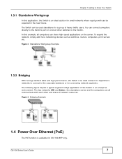
...In this application, the Switch is an ideal solution for a group of the Switch in the near future. Figure 3 Bridging Example 1.4 Power Over Ethernet (PoE) The PoE function is an ideal solution for department networks to connect to the corporate backbone or for GS1100-8HP only. To ...expand the network, simply add more networking devices such as switches, routers, computers, print servers etc. The following figure depicts a typical segment bridge application of heavy...
...In this application, the Switch is an ideal solution for a group of the Switch in the near future. Figure 3 Bridging Example 1.4 Power Over Ethernet (PoE) The PoE function is an ideal solution for department networks to connect to the corporate backbone or for GS1100-8HP only. To ...expand the network, simply add more networking devices such as switches, routers, computers, print servers etc. The following figure depicts a typical segment bridge application of heavy...
User Guide
Page 8
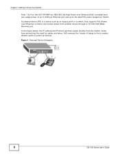
Figure 4 Powered Device Examples 8 GS1100 Series User's Guide Aside from the Switch. Chapter 1 Getting to Know Your Switch Ports 1 to 4 on the GS1100-8HP are IEEE 802.3at High Power over Ethernet) so that supports PoE (Power over Ethernet (PoE) compliant and can receive power from another device ... minimizing the need for cables and wires, PoE removes the hassle of up to the total PoE power budget per Switch. A powered device (PD) is a device such as an access point or a switch, that it can supply power of trying to find a nearby electric outlet to power up to 30W per Ethernet...
Figure 4 Powered Device Examples 8 GS1100 Series User's Guide Aside from the Switch. Chapter 1 Getting to Know Your Switch Ports 1 to 4 on the GS1100-8HP are IEEE 802.3at High Power over Ethernet) so that supports PoE (Power over Ethernet (PoE) compliant and can receive power from another device ... minimizing the need for cables and wires, PoE removes the hassle of up to the total PoE power budget per Switch. A powered device (PD) is a device such as an access point or a switch, that it can supply power of trying to find a nearby electric outlet to power up to 30W per Ethernet...

User Guide
Page 9
...to the power receptacle on or off. 2.2 Front Panel The front panel of the Switch and the other end to the appropriate power source. Figure 5 Rear Panel GS1100-8HP GS1100-16 GS1100-24 GS1100-24E 2.1.1 Rear Panel Power Connection Connect one end of the supplied power cord or... power adaptor to the power supply requirements on the rear panel of the Switch. GS1100 Series User's Guide 9 CHAPTER 2 Hardware Description...
...to the power receptacle on or off. 2.2 Front Panel The front panel of the Switch and the other end to the appropriate power source. Figure 5 Rear Panel GS1100-8HP GS1100-16 GS1100-24 GS1100-24E 2.1.1 Rear Panel Power Connection Connect one end of the supplied power cord or... power adaptor to the power supply requirements on the rear panel of the Switch. GS1100 Series User's Guide 9 CHAPTER 2 Hardware Description...

User Guide
Page 10
... that connect to go into the slot with transceivers. This allows the Switch to the Switch doesn't support EEE, EEE may not work in the Switch. If one of receive and transmit circuitry when it . 2.2.3 SFP Slots (GS1100-24 Only) These are auto-negotiating and auto-crossover. Press in the...Ethernet cable. 2.2.2 IEEE 802.3az EEE The Switch supports the IEEE 802.3az EEE (Energy Efficient Ethernet) standard to the optimum Ethernet speed (10/100/1000 Mpbs) and duplex mode (full duplex or half duplex) of PCB board facing down. 10 GS1100 Series User's Guide Chapter 2 Hardware Description ...
... that connect to go into the slot with transceivers. This allows the Switch to the Switch doesn't support EEE, EEE may not work in the Switch. If one of receive and transmit circuitry when it . 2.2.3 SFP Slots (GS1100-24 Only) These are auto-negotiating and auto-crossover. Press in the...Ethernet cable. 2.2.2 IEEE 802.3az EEE The Switch supports the IEEE 802.3az EEE (Energy Efficient Ethernet) standard to the optimum Ethernet speed (10/100/1000 Mpbs) and duplex mode (full duplex or half duplex) of PCB board facing down. 10 GS1100 Series User's Guide Chapter 2 Hardware Description ...

User Guide
Page 11
Figure 8 Removing the Fiber Optic Cables Figure 9 Opening the Transceiver's Latch Example GS1100 Series User's Guide 11 Figure 6 Transceiver Installation Example Figure 7 Connecting the Fiber Optic Cables 2.2.3.2 Transceiver Removal Use the following steps to the transceiver. Chapter 2 Hardware .... 2 Open the transceiver's latch (latch styles vary). 3 Pull the transceiver out of the slot. Check the LEDs to verify that it clicks into place. 3 The Switch automatically detects the installed transceiver.
Figure 8 Removing the Fiber Optic Cables Figure 9 Opening the Transceiver's Latch Example GS1100 Series User's Guide 11 Figure 6 Transceiver Installation Example Figure 7 Connecting the Fiber Optic Cables 2.2.3.2 Transceiver Removal Use the following steps to the transceiver. Chapter 2 Hardware .... 2 Open the transceiver's latch (latch styles vary). 3 Pull the transceiver out of the slot. Check the LEDs to verify that it clicks into place. 3 The Switch automatically detects the installed transceiver.

User Guide
Page 12
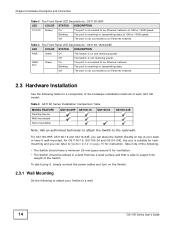
... provides descriptions of network cable used for all the ports. 2.2.5 Front Panel LEDs The LED Indicators give real-time information about the status of the Switch. Table 2 Network Cable Types SPEED NETWORK CABLE TYPE 10 Mbps Category 3, 4 or 5 UTP/STP 100 Mbps Category 5 UTP/STP 1000 Mbps Category 5e, 6 UTP/STP... You can use either crossover or straight-through cables for the different connection speeds. . The following table describes the types of the LEDs. 12 GS1100 Series User's Guide
... provides descriptions of network cable used for all the ports. 2.2.5 Front Panel LEDs The LED Indicators give real-time information about the status of the Switch. Table 2 Network Cable Types SPEED NETWORK CABLE TYPE 10 Mbps Category 3, 4 or 5 UTP/STP 100 Mbps Category 5 UTP/STP 1000 Mbps Category 5e, 6 UTP/STP... You can use either crossover or straight-through cables for the different connection speeds. . The following table describes the types of the LEDs. 12 GS1100 Series User's Guide

User Guide
Page 13
... Amber On Power is supplied to the PoE port(s) is receiving or transmitting data at 1000M speed. GS1100 Series User's Guide 13 Off The Switch is on the Switch. Figure 11 Front Panel LEDs GS1100-8HP GS1100-16 GS1100-24 GS1100-24E Chapter 2 Hardware Description and Connection The following table describes the LEDs. Blinking The port is below...
... Amber On Power is supplied to the PoE port(s) is receiving or transmitting data at 1000M speed. GS1100 Series User's Guide 13 Off The Switch is on the Switch. Figure 11 Front Panel LEDs GS1100-8HP GS1100-16 GS1100-24 GS1100-24E Chapter 2 Hardware Description and Connection The following table describes the LEDs. Blinking The port is below...
User Guide
Page 14
...On The port is connected to the rack/wall. Blinking The port is not receiving power. For GS1100-8HP, GS1100-16 and GS110-24E, you can place the Switch directly on the Switch. 2.3.1 Wall Mounting Do the following to attach your desk or have a minimum 25 mm space ... the power cables and turn on top of each GS1100 model: Table 5 GS1100 Series Installation Comparison Table MODEL FEATURE Desktop Device Wall-mountable Rack-mountable GS1100-8HP GS1100-16 GS1100-24 GS1100-24E Note: Ask an authorized technician to attach the Switch to an Ethernet network at 10M or 100M speed....
...On The port is connected to the rack/wall. Blinking The port is not receiving power. For GS1100-8HP, GS1100-16 and GS110-24E, you can place the Switch directly on the Switch. 2.3.1 Wall Mounting Do the following to attach your desk or have a minimum 25 mm space ... the power cables and turn on top of each GS1100 model: Table 5 GS1100 Series Installation Comparison Table MODEL FEATURE Desktop Device Wall-mountable Rack-mountable GS1100-8HP GS1100-16 GS1100-24 GS1100-24E Note: Ask an authorized technician to attach the Switch to an Ethernet network at 10M or 100M speed....
User Guide
Page 15
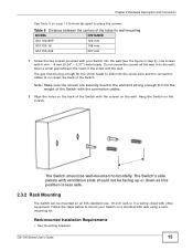
... page 15 for how far apart to hold the weight of the Switch with the connection cables. 2 Align the holes on the back of the Switch with the screws on the wall. The Switch's side panels with other equipment. The Switch should not be big enough for the screw heads to slide into the... enough to place the screws. The gap must be facing up or down the back of the holes for wall mounting MODEL GS1100-8HP GS1100-16 DISTANCE 120 mm 148 mm GS1100-24E 207 mm 1 Screw the two screws provided with 6 mm ~ 8 mm (0.24" ~ 0.31") wide heads. Table 6 Distance between the head of the...
... page 15 for how far apart to hold the weight of the Switch with the connection cables. 2 Align the holes on the back of the Switch with the screws on the wall. The Switch's side panels with other equipment. The Switch should not be big enough for the screw heads to slide into the... enough to place the screws. The gap must be facing up or down the back of the holes for wall mounting MODEL GS1100-8HP GS1100-16 DISTANCE 120 mm 148 mm GS1100-24E 207 mm 1 Screw the two screws provided with 6 mm ~ 8 mm (0.24" ~ 0.31") wide heads. Table 6 Distance between the head of the...

User Guide
Page 16
... the rack will safely support the combined weight of the Switch. Figure 12 Attaching the Mounting Brackets (GS1100-16 and GS1100-24E) Figure 13 Attaching the Mounting Brackets (GS1100-24) 2 Using a #2 Philips screwdriver, install the M3 flat head screws through the mounting bracket holes into the Switch. 3 Repeat steps 1 and 2 to anchor the rack securely before...
... the rack will safely support the combined weight of the Switch. Figure 12 Attaching the Mounting Brackets (GS1100-16 and GS1100-24E) Figure 13 Attaching the Mounting Brackets (GS1100-24) 2 Using a #2 Philips screwdriver, install the M3 flat head screws through the mounting bracket holes into the Switch. 3 Repeat steps 1 and 2 to anchor the rack securely before...

User Guide
Page 17
Chapter 2 Hardware Description and Connection Figure 14 Mounting the Switch on a Rack (GS1100-16 and GS1100-24E) Figure 15 Mounting the Switch on a Rack (GS1100-24) 2 Using a #2 Philips screwdriver, install the M5 flat head screws through the mounting bracket holes into the rack. 3 Repeat steps 1 and 2 to attach the second mounting bracket on the other side of the rack. GS1100 Series User's Guide 17
Chapter 2 Hardware Description and Connection Figure 14 Mounting the Switch on a Rack (GS1100-16 and GS1100-24E) Figure 15 Mounting the Switch on a Rack (GS1100-24) 2 Using a #2 Philips screwdriver, install the M5 flat head screws through the mounting bracket holes into the rack. 3 Repeat steps 1 and 2 to attach the second mounting bracket on the other side of the rack. GS1100 Series User's Guide 17
User Guide
Page 19
Troubleshoot the Switch using an appropriate power source. For more information on network cable types, see that the power adaptor is securely connected to the GS1100-8HP and an appropriate power source. GS1100 Series User's Guide 19 The PoE LED is off and/or power is turned on and properly... connected to see Section 3.1 on the front panel does not light up when a device is connected. • Verify that the Switch is ...
Troubleshoot the Switch using an appropriate power source. For more information on network cable types, see that the power adaptor is securely connected to the GS1100-8HP and an appropriate power source. GS1100 Series User's Guide 19 The PoE LED is off and/or power is turned on and properly... connected to see Section 3.1 on the front panel does not light up when a device is connected. • Verify that the Switch is ...

User Guide
Page 21
...take adequate measures. APPENDIX A Legal Information Copyright Copyright © 2013 by region. Published by the party responsible for a Class A digital switch, pursuant to whatever extent it convey any products, or software described herein. This publication is free from the date of the FCC Rules....://www.zyxel.com to correct the interference at the discretion of others. Check with the instruction manual, may be required to view this product may cause radio interference in which case the user will , at its patent rights nor the patent rights of ZyXEL. GS1100 Series ...
...take adequate measures. APPENDIX A Legal Information Copyright Copyright © 2013 by region. Published by the party responsible for a Class A digital switch, pursuant to whatever extent it convey any products, or software described herein. This publication is free from the date of the FCC Rules....://www.zyxel.com to correct the interference at the discretion of others. Check with the instruction manual, may be required to view this product may cause radio interference in which case the user will , at its patent rights nor the patent rights of ZyXEL. GS1100 Series ...