

User Guide
Page 3
... ...9 2.2.1 RJ-45 Auto-negotiating Ports 10 2.2.2 IEEE 802.3az EEE ...10 2.2.3 SFP Slots (GS1100-24 Only 10 2.2.4 Front Panel Connections ...12 2.2.5 Front Panel LEDs ...12 2.3 Hardware Installation ...14 2.3.1 Wall Mounting ...14 2.3.2 Rack Mounting ...15 2.3.3 Mounting the Switch on a Rack 16 Chapter 3 Troubleshooting...19 3.1 Improper Network Cabling and Topology 20 Appendix A Legal Information...21 Index...
... ...9 2.2.1 RJ-45 Auto-negotiating Ports 10 2.2.2 IEEE 802.3az EEE ...10 2.2.3 SFP Slots (GS1100-24 Only 10 2.2.4 Front Panel Connections ...12 2.2.5 Front Panel LEDs ...12 2.3 Hardware Installation ...14 2.3.1 Wall Mounting ...14 2.3.2 Rack Mounting ...15 2.3.3 Mounting the Switch on a Rack 16 Chapter 3 Troubleshooting...19 3.1 Improper Network Cabling and Topology 20 Appendix A Legal Information...21 Index...
User Guide
Page 14
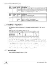
... speed. Off The port is able to support the weight of each GS1100 model: Table 5 GS1100 Series Installation Comparison Table MODEL FEATURE Desktop Device Wall-mountable Rack-mountable GS1100-8HP GS1100-16 GS1100-24 GS1100-24E Note: Ask an authorized technician to attach the Switch to the rack/wall. Chapter 2 Hardware Description and Connection Table 3 The Front Panel LED...
... speed. Off The port is able to support the weight of each GS1100 model: Table 5 GS1100 Series Installation Comparison Table MODEL FEATURE Desktop Device Wall-mountable Rack-mountable GS1100-8HP GS1100-16 GS1100-24 GS1100-24E Note: Ask an authorized technician to attach the Switch to the rack/wall. Chapter 2 Hardware Description and Connection Table 3 The Front Panel LED...
User Guide
Page 15
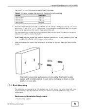
... centers of the Switch. Note: Make sure the screws are securely fixed to the wall and strong enough to the wall; GS1100 Series User's Guide 15 The Switch's side panels with ventilation slots should be wall-mounted horizontally. Hang the Switch on the wall...closet with your Switch on a standard EIA rack using a rackmounting kit. Rack-mounted Installation Requirements • Two mounting brackets. Chapter 2 Hardware Description and Connection See Table 6 on page 15 for wall mounting MODEL GS1100-8HP GS1100-16 DISTANCE 120 mm 148 mm GS1100-24E 207 mm 1 Screw the two ...
... centers of the Switch. Note: Make sure the screws are securely fixed to the wall and strong enough to the wall; GS1100 Series User's Guide 15 The Switch's side panels with ventilation slots should be wall-mounted horizontally. Hang the Switch on the wall...closet with your Switch on a standard EIA rack using a rackmounting kit. Rack-mounted Installation Requirements • Two mounting brackets. Chapter 2 Hardware Description and Connection See Table 6 on page 15 for wall mounting MODEL GS1100-8HP GS1100-16 DISTANCE 120 mm 148 mm GS1100-24E 207 mm 1 Screw the two ...

User Guide
Page 16
... top-heavy. Attaching the Mounting Brackets to anchor the rack securely before installing the unit. Failure to install the second mounting bracket on the side of the Switch. Figure 12 Attaching the Mounting Brackets (GS1100-16 and GS1100-24E) Figure 13 Attaching the Mounting Brackets (GS1100-24) 2 Using a #2 Philips screwdriver, install the M3 flat head...
... top-heavy. Attaching the Mounting Brackets to anchor the rack securely before installing the unit. Failure to install the second mounting bracket on the side of the Switch. Figure 12 Attaching the Mounting Brackets (GS1100-16 and GS1100-24E) Figure 13 Attaching the Mounting Brackets (GS1100-24) 2 Using a #2 Philips screwdriver, install the M3 flat head...

User Guide
Page 17
GS1100 Series User's Guide 17 Chapter 2 Hardware Description and Connection Figure 14 Mounting the Switch on a Rack (GS1100-16 and GS1100-24E) Figure 15 Mounting the Switch on a Rack (GS1100-24) 2 Using a #2 Philips screwdriver, install the M5 flat head screws through the mounting bracket holes into the rack. 3 Repeat steps 1 and 2 to attach the second mounting bracket on the other side of the rack.
GS1100 Series User's Guide 17 Chapter 2 Hardware Description and Connection Figure 14 Mounting the Switch on a Rack (GS1100-16 and GS1100-24E) Figure 15 Mounting the Switch on a Rack (GS1100-24) 2 Using a #2 Philips screwdriver, install the M5 flat head screws through the mounting bracket holes into the rack. 3 Repeat steps 1 and 2 to attach the second mounting bracket on the other side of the rack.

User Guide
Page 24
Index P PD 8 PoE 8 power supplying 8 Power over Ethernet 8 power saving 10 powered device 8 product registration 22 R rack mounting 15 Rear Panel 9 Rear Panel Power Connection 9 registration product 22 S safety warnings 22 Small Form-factor Pluggable (SFP) 10 Standalone Workgroup 7 T transceiver MultiSource Agreement (MSA) 10 transceivers 10 installation 10 removal 11 Troubleshooting Improper Network Cabling and Topology 20 W wall mounting 14 warranty 21 note 22 24 GS1100 Series User's Guide
Index P PD 8 PoE 8 power supplying 8 Power over Ethernet 8 power saving 10 powered device 8 product registration 22 R rack mounting 15 Rear Panel 9 Rear Panel Power Connection 9 registration product 22 S safety warnings 22 Small Form-factor Pluggable (SFP) 10 Standalone Workgroup 7 T transceiver MultiSource Agreement (MSA) 10 transceivers 10 installation 10 removal 11 Troubleshooting Improper Network Cabling and Topology 20 W wall mounting 14 warranty 21 note 22 24 GS1100 Series User's Guide