
User Guide
Page 5
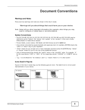
Syntax Conventions • The ES1100-8P, ES1100-16, ES1100-16P, ES1100-24, ES1100-24E and ES1100-24G may use one or more characters and then press the [ENTER] key. Icons Used in Figures Figures in this User's Guide may be referred ... to use the following generic icons. "Select" or "choose" means for you to configure or helpful tips) or recommendations. The Switch Computer Notebook computer Server ES1100 Series User's Guide 5
Syntax Conventions • The ES1100-8P, ES1100-16, ES1100-16P, ES1100-24, ES1100-24E and ES1100-24G may use one or more characters and then press the [ENTER] key. Icons Used in Figures Figures in this User's Guide may be referred ... to use the following generic icons. "Select" or "choose" means for you to configure or helpful tips) or recommendations. The Switch Computer Notebook computer Server ES1100 Series User's Guide 5
User Guide
Page 7
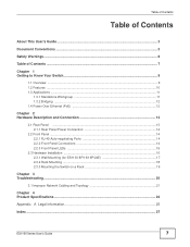
... Panel Power Connection 14 2.2 Front Panel ...14 2.2.1 RJ-45 Auto-negotiating Ports 14 2.2.2 Front Panel Connections 14 2.2.3 Front Panel LEDs ...15 2.3 Hardware Installation ...16 2.3.1 Wall Mounting (for ES1100-8P/16/16P/24E 17 2.3.2 Rack Mounting ...18 2.3.3 Mounting the Switch on a Rack 19 Chapter 3 Troubleshooting...20 3.1 Improper Network Cabling and Topology 21 Chapter 4 Product Specifications...
... Panel Power Connection 14 2.2 Front Panel ...14 2.2.1 RJ-45 Auto-negotiating Ports 14 2.2.2 Front Panel Connections 14 2.2.3 Front Panel LEDs ...15 2.3 Hardware Installation ...16 2.3.1 Wall Mounting (for ES1100-8P/16/16P/24E 17 2.3.2 Rack Mounting ...18 2.3.3 Mounting the Switch on a Rack 19 Chapter 3 Troubleshooting...20 3.1 Improper Network Cabling and Topology 21 Chapter 4 Product Specifications...
User Guide
Page 9
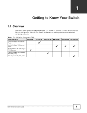
Table 1 ES1100 Series Comparison Table PORT DETAILS ES1100-8P ES1100-16 16x10/100Base-TX Ethernet Ports 24x10/100Base-TX Ethernet Ports 8x10/100Base-TX (including 4 FE PoE ports) 16x10/100Base-TX (including 8 FE PoE ports) 2 dual-personality GbE ports ES1100-16P ES1100-24 ES1100-24E ES1100-24G ES1100 Series User's Guide 9 The Switch can be used to Know Your Switch 1.1 Overview This User's Guide covers the following models: ES1100-8P, ES1100-16, ES1100-16P, ES1100-24, ES1100-24E, and ES1100-24G. CHAPTER 1 Getting to build high-performance switched workgroup networks.
Table 1 ES1100 Series Comparison Table PORT DETAILS ES1100-8P ES1100-16 16x10/100Base-TX Ethernet Ports 24x10/100Base-TX Ethernet Ports 8x10/100Base-TX (including 4 FE PoE ports) 16x10/100Base-TX (including 8 FE PoE ports) 2 dual-personality GbE ports ES1100-16P ES1100-24 ES1100-24E ES1100-24G ES1100 Series User's Guide 9 The Switch can be used to Know Your Switch 1.1 Overview This User's Guide covers the following models: ES1100-8P, ES1100-16, ES1100-16P, ES1100-24, ES1100-24E, and ES1100-24G. CHAPTER 1 Getting to build high-performance switched workgroup networks.
User Guide
Page 10
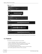
Chapter 1 Getting to Know Your Switch Figure 1 Front Panel ES1100-8P ES1100-16 ES1100-16P ES1100-24 ES1100-24E ES1100-24G The Switch has a built-in algorithm that automatically assigns priority to received packets. 1.2 Features The following are the essential features of the Switch. • ...
Chapter 1 Getting to Know Your Switch Figure 1 Front Panel ES1100-8P ES1100-16 ES1100-16P ES1100-24 ES1100-24E ES1100-24G The Switch has a built-in algorithm that automatically assigns priority to received packets. 1.2 Features The following are the essential features of the Switch. • ...
User Guide
Page 11
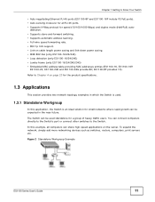
...power saving. • IEEE 802.3az (only ES1100-16/24/24E) • Loop detection (only ES1100-16/24/24E) • Jumbo frame (only ES1100-16/24/24E/24G) • Embedded MAC address table providing MAC addresses entries (ES1100-16, ES1100-16P, ES1100-24, ES1100-24E and ES1100-24G provide 8K; detection. • Supports store..., simply add more networking devices such as switches, routers, computers, print servers etc. Figure 2 Standalone Workgroup Example ES1100 Series User's Guide 11 The Switch can be expected in which the Switch is used standalone for the product specifications....
...power saving. • IEEE 802.3az (only ES1100-16/24/24E) • Loop detection (only ES1100-16/24/24E) • Jumbo frame (only ES1100-16/24/24E/24G) • Embedded MAC address table providing MAC addresses entries (ES1100-16, ES1100-16P, ES1100-24, ES1100-24E and ES1100-24G provide 8K; detection. • Supports store..., simply add more networking devices such as switches, routers, computers, print servers etc. Figure 2 Standalone Workgroup Example ES1100 Series User's Guide 11 The Switch can be expected in which the Switch is used standalone for the product specifications....

User Guide
Page 13
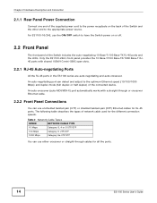
Figure 5 Rear Panel ES1100-8P ES1100-16 ES1100-16P ES1100-24 ES1100-24E ES1100-24G ES1100 Series User's Guide 13 Refer to the Product Specifications on the rear panel of the Switch. CHAPTER 2 Hardware Description and Connection 2.1 Rear Panel The three-pronged power receptacle is located on page 23 for power specification.
Figure 5 Rear Panel ES1100-8P ES1100-16 ES1100-16P ES1100-24 ES1100-24E ES1100-24G ES1100 Series User's Guide 13 Refer to the Product Specifications on the rear panel of the Switch. CHAPTER 2 Hardware Description and Connection 2.1 Rear Panel The three-pronged power receptacle is located on page 23 for power specification.
User Guide
Page 14
...through cables for RJ-45 ports. The following table describes the types of network cable used for the different connection speeds. For ES1100-16/24E, use either crossover or straight-through or crossover Ethernet cable. 2.2.2 Front Panel Connections You can detect and adjust to the appropriate ...auto-negotiating port can use unshielded twisted pair (UTP) or shielded twisted-pair (STP) Ethernet cables for all the ports. 14 ES1100 Series User's Guide Chapter 2 Hardware Description and Connection 2.1.1 Rear Panel Power Connection Connect one end of the supplied power cord to ...
...through cables for RJ-45 ports. The following table describes the types of network cable used for the different connection speeds. For ES1100-16/24E, use either crossover or straight-through or crossover Ethernet cable. 2.2.2 Front Panel Connections You can detect and adjust to the appropriate ...auto-negotiating port can use unshielded twisted pair (UTP) or shielded twisted-pair (STP) Ethernet cables for all the ports. 14 ES1100 Series User's Guide Chapter 2 Hardware Description and Connection 2.1.1 Rear Panel Power Connection Connect one end of the supplied power cord to ...
User Guide
Page 15
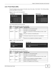
... Green On The port is connected to an Ethernet network. Off The port is on and receiving power. Figure 7 LEDs for ES1100-16/24/24E LED COLOR STATUS DESCRIPTION PWR Green On The Switch is not connected to an Ethernet network at 10M or 100M speed. LINK/ACT... an Ethernet network at 10M or 100M speed. Off Power is connected to the FE PoE port. Table 4 LED Descriptions for ES1100-16/24/24E ES1100-16 ES1100-24 ES1100-24E The following tables provide descriptions of the Switch. Off The Switch is not receiving power. Off The Switch is not receiving power....
... Green On The port is connected to an Ethernet network. Off The port is on and receiving power. Figure 7 LEDs for ES1100-16/24/24E LED COLOR STATUS DESCRIPTION PWR Green On The Switch is not connected to an Ethernet network at 10M or 100M speed. LINK/ACT... an Ethernet network at 10M or 100M speed. Off Power is connected to the FE PoE port. Table 4 LED Descriptions for ES1100-16/24/24E ES1100-16 ES1100-24 ES1100-24E The following tables provide descriptions of the Switch. Off The Switch is not receiving power. Off The Switch is not receiving power....
User Guide
Page 16
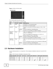
...port is not connected to an Ethernet network at 100M speed. Chapter 2 Hardware Description and Connection Figure 8 LEDs for ES1100-24G LED PWR LINK/ACT LINK/ACT (Gigabit Ethernet) LINK/ACT (Mini-GBIC) COLOR Green Green Green Green STATUS ...5 LED Descriptions for ES1100-24G ES1100-24G The following table for a comparison of the hardware installation methods of each ES1100 model: Table 6 ES1100 Series Installation Comparison Table MODEL FEATURE Desktop Device Wall-mountable Rack-mountable ES1100-8P ES1100-16 ES1100-16P ES1100-24 ES1100-24E ES1100-24G 16 ES1100 Series User's Guide ...
...port is not connected to an Ethernet network at 100M speed. Chapter 2 Hardware Description and Connection Figure 8 LEDs for ES1100-24G LED PWR LINK/ACT LINK/ACT (Gigabit Ethernet) LINK/ACT (Mini-GBIC) COLOR Green Green Green Green STATUS ...5 LED Descriptions for ES1100-24G ES1100-24G The following table for a comparison of the hardware installation methods of each ES1100 model: Table 6 ES1100 Series Installation Comparison Table MODEL FEATURE Desktop Device Wall-mountable Rack-mountable ES1100-8P ES1100-16 ES1100-16P ES1100-24 ES1100-24E ES1100-24G 16 ES1100 Series User's Guide ...
User Guide
Page 17
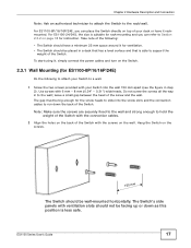
...position is suitable for rack-mounting and you can refer to Section 2.3.2 on page 18 for ventilation. • The Switch should be big enough for ES1100-8P/16/16P/24E) Do the following : • The Switch should not be wall-mounted horizontally. Do not screw the screws all the way in step 2). For... ES1100-8P/16/16P/24E, you can place the Switch directly on top of your desk or have a minimum 25 mm space around it rackmounted. Note: Make sure the ...
...position is suitable for rack-mounting and you can refer to Section 2.3.2 on page 18 for ventilation. • The Switch should be big enough for ES1100-8P/16/16P/24E) Do the following : • The Switch should not be wall-mounted horizontally. Do not screw the screws all the way in step 2). For... ES1100-8P/16/16P/24E, you can place the Switch directly on top of your desk or have a minimum 25 mm space around it rackmounted. Note: Make sure the ...
User Guide
Page 18
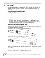
...of all necessary precautions to install the second mounting bracket on the other equipment. Figure 9 Attaching the Mounting Brackets (ES1100-8P/16/16P/24E) Figure 10 Attaching the Mounting Brackets (ES1100-24/24G) 2 Using a #2 Philips screwdriver, install the M3 flat head screws through the mounting bracket holes into ...8226; Make sure the position of the Switch does not make the rack unstable or top-heavy. Failure to the next section. 18 ES1100 Series User's Guide Proceed to use the proper screws may now mount the Switch on a standard EIA rack using a rackmounting kit. Chapter...
...of all necessary precautions to install the second mounting bracket on the other equipment. Figure 9 Attaching the Mounting Brackets (ES1100-8P/16/16P/24E) Figure 10 Attaching the Mounting Brackets (ES1100-24/24G) 2 Using a #2 Philips screwdriver, install the M3 flat head screws through the mounting bracket holes into ...8226; Make sure the position of the Switch does not make the rack unstable or top-heavy. Failure to the next section. 18 ES1100 Series User's Guide Proceed to use the proper screws may now mount the Switch on a standard EIA rack using a rackmounting kit. Chapter...

User Guide
Page 19
Figure 11 Mounting the Switch on a Rack (ES1100-8P/16/16P/24E) Figure 12 Mounting the Switch on a Rack (ES1100-24/24G) 2 Using a #2 Philips screwdriver, install the M5 flat head screws through the mounting bracket holes into the rack. 3 Repeat steps 1 and 2 to the Switch) ... one side of the rack, lining up the two screw holes on the bracket with the screw holes on the other side of the rack. ES1100 Series User's Guide 19 Chapter 2 Hardware Description and Connection 2.3.3 Mounting the Switch on a Rack 1 Position a mounting bracket (that is already attached to attach the second...
Figure 11 Mounting the Switch on a Rack (ES1100-8P/16/16P/24E) Figure 12 Mounting the Switch on a Rack (ES1100-24/24G) 2 Using a #2 Philips screwdriver, install the M5 flat head screws through the mounting bracket holes into the rack. 3 Repeat steps 1 and 2 to the Switch) ... one side of the rack, lining up the two screw holes on the bracket with the screw holes on the other side of the rack. ES1100 Series User's Guide 19 Chapter 2 Hardware Description and Connection 2.3.3 Mounting the Switch on a Rack 1 Position a mounting bracket (that is already attached to attach the second...
User Guide
Page 23
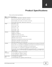
... are the product specifications. Table 7 Product Specifications Dimension ES1100-8P/16P: 265mm(W) x 184mm(D) x 44mm(H) ES1100-16: 216 mm (W) x 133 mm (D) x 42 mm (H) ES1100-24/24G: 441 mm (W) x 131 mm (D) x 44 mm (H) Weight ES1100-24E: 267 mm (W) x 162 mm (D) x 42 mm (H) ES1100-8P: 1.4 kg ES1100-16: 0.8 kg ES1100-16P: 1.7 kg ES1100-24: 1.5 kg ES1100-24E: 1.3 kg Standard ES1100-24G: 1.8 kg IEEE802.3 10 BASE-T IEEE802.3u...
... are the product specifications. Table 7 Product Specifications Dimension ES1100-8P/16P: 265mm(W) x 184mm(D) x 44mm(H) ES1100-16: 216 mm (W) x 133 mm (D) x 42 mm (H) ES1100-24/24G: 441 mm (W) x 131 mm (D) x 44 mm (H) Weight ES1100-24E: 267 mm (W) x 162 mm (D) x 42 mm (H) ES1100-8P: 1.4 kg ES1100-16: 0.8 kg ES1100-16P: 1.7 kg ES1100-24: 1.5 kg ES1100-24E: 1.3 kg Standard ES1100-24G: 1.8 kg IEEE802.3 10 BASE-T IEEE802.3u...

User Guide
Page 24
...: 100~240VAC 50/60Hz 2A Max • ES1100-24/24E: 100~240VAC 50/60Hz 0.5A Max • ES1100-24G: 100~240VAC 50/60Hz 0.3A Max Power consumption: Safety EMC • ES1100-8P: 74.9W max. • ES1100-16: 2.65W max. • ES1100-16P: 161.6 W max. • ES1100-24/24E: 4.05W max. • ES1100-24G: 14.7W max EN 60950-1 FCC...
...: 100~240VAC 50/60Hz 2A Max • ES1100-24/24E: 100~240VAC 50/60Hz 0.5A Max • ES1100-24G: 100~240VAC 50/60Hz 0.3A Max Power consumption: Safety EMC • ES1100-8P: 74.9W max. • ES1100-16: 2.65W max. • ES1100-16P: 161.6 W max. • ES1100-24/24E: 4.05W max. • ES1100-24G: 14.7W max EN 60950-1 FCC...