

Owner's Manual
Page 2
... to persons. or B. An outdoor antenna should be situated away from power lines. 18 Grounding or Polarization - NO USER-SERVICEABLE PARTS INSIDE. REFER SERVICING TO QUALIFIED SERVICE PERSONNEL. • Explanation of air through the ventilation openings. 2 9 Heat - Quick stops, excessive force, and uneven surfaces may impede the flow of Graphical Symbols The lightning flash with a cart or stand that...
... to persons. or B. An outdoor antenna should be situated away from power lines. 18 Grounding or Polarization - NO USER-SERVICEABLE PARTS INSIDE. REFER SERVICING TO QUALIFIED SERVICE PERSONNEL. • Explanation of air through the ventilation openings. 2 9 Heat - Quick stops, excessive force, and uneven surfaces may impede the flow of Graphical Symbols The lightning flash with a cart or stand that...
Owner's Manual
Page 3
..., Part 15 for Class "B" digital devices. Utilize power outlets that your FCC authorization to coaxial type cable. One that is found in the users manual, may void your authority, granted by Yamaha may cause interference harmful to follow instructions could void your use the product. 2. Since hearing damage from loud sounds is often undetectable until it at a safe level. Follow all installations. and...
..., Part 15 for Class "B" digital devices. Utilize power outlets that your FCC authorization to coaxial type cable. One that is found in the users manual, may void your authority, granted by Yamaha may cause interference harmful to follow instructions could void your use the product. 2. Since hearing damage from loud sounds is often undetectable until it at a safe level. Follow all installations. and...
Owner's Manual
Page 4
... place for any accident caused by super-bass frequencies may cause images on the rear of at least 20 cm above, behind and on switches, controls or connection wires. Extremely loud playing of time (i.e., vacation, etc.), disconnect the AC power plug from the rear panel. Secure placement or installation is an electrical storm. 9. Serial No.: The serial number is located on a TV to the terminal...
... place for any accident caused by super-bass frequencies may cause images on the rear of at least 20 cm above, behind and on switches, controls or connection wires. Extremely loud playing of time (i.e., vacation, etc.), disconnect the AC power plug from the rear panel. Secure placement or installation is an electrical storm. 9. Serial No.: The serial number is located on a TV to the terminal...
Owner's Manual
Page 5
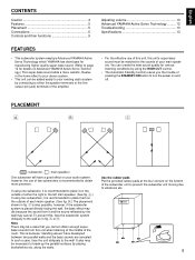
... either the speaker terminals or the line output (pin jack) terminals of the amplifier. • For the effective use of the room. English CONTENTS Caution 4 Features 5 Placement 5 Connections 6 Controls and their functions 9 Adjusting volume 10 Advanced YAMAHA Active Servo Technology ......... 12 Troubleshooting 13 Specifications 13 FEATURES • This subwoofer system employs Advanced YAMAHA Active Servo Technology which YAMAHA has developed for reproducing higher quality super-bass sound. (Refer...
... either the speaker terminals or the line output (pin jack) terminals of the amplifier. • For the effective use of the room. English CONTENTS Caution 4 Features 5 Placement 5 Connections 6 Controls and their functions 9 Adjusting volume 10 Advanced YAMAHA Active Servo Technology ......... 12 Troubleshooting 13 Specifications 13 FEATURES • This subwoofer system employs Advanced YAMAHA Active Servo Technology which YAMAHA has developed for reproducing higher quality super-bass sound. (Refer...
Owner's Manual
Page 6
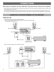
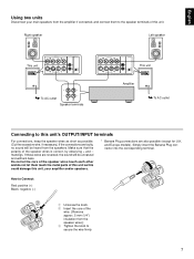
... output (pin jack) terminals of speaker terminals Right speaker This unit OUTPUT TO SPEAKERS INPUT2 AUTO STANDBY FROM AMPLIFIER INPUT1 LOW HIGH OFF POWER ON OFF OUTPUT TO SPEAKERS INPUT2 AUTO STANDBY FROM AMPLIFIER INPUT1 LOW HIGH OFF To AC outlet Left speaker Speaker terminals A B Amplifier (Both A and B speaker outputs must be sure all connections are completed. • When making connections between this unit. L (left) to L, R (right) to R, + to the owner's manuals supplied for your audio system. CONNECTING...
... output (pin jack) terminals of speaker terminals Right speaker This unit OUTPUT TO SPEAKERS INPUT2 AUTO STANDBY FROM AMPLIFIER INPUT1 LOW HIGH OFF POWER ON OFF OUTPUT TO SPEAKERS INPUT2 AUTO STANDBY FROM AMPLIFIER INPUT1 LOW HIGH OFF To AC outlet Left speaker Speaker terminals A B Amplifier (Both A and B speaker outputs must be sure all connections are completed. • When making connections between this unit. L (left) to L, R (right) to R, + to the owner's manuals supplied for your audio system. CONNECTING...
Owner's Manual
Page 7
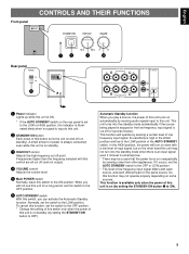
... LOW HIGH OFF To AC outlet Speaker terminals OUTPUT TO SPEAKERS FROM AMPLIFIER INPUT1 INPUT2 AUTO STANDBY LOW HIGH OFF This unit OUTPUT TO SPEAKERS INPUT2 AUTO STANDBY FROM AMPLIFIER INPUT1 LOW HIGH OFF Amplifier POWER ON OFF To AC outlet Connecting to this unit's OUTPUT/INPUT terminals For connections, keep the speaker wires as short as this could damage this unit, your main speakers from the amplifier if connected, and connect them touch the metal parts...
... LOW HIGH OFF To AC outlet Speaker terminals OUTPUT TO SPEAKERS FROM AMPLIFIER INPUT1 INPUT2 AUTO STANDBY LOW HIGH OFF This unit OUTPUT TO SPEAKERS INPUT2 AUTO STANDBY FROM AMPLIFIER INPUT1 LOW HIGH OFF Amplifier POWER ON OFF To AC outlet Connecting to this unit's OUTPUT/INPUT terminals For connections, keep the speaker wires as short as this could damage this unit, your main speakers from the amplifier if connected, and connect them touch the metal parts...

Owner's Manual
Page 8
... right INPUT 2 terminal. • For using a power amplifier and a preamplifier, the preamplifier must have two sets of PRE OUT terminals. CONNECTING TO LINE OUTPUT (PIN JACK) TERMINALS OF THE AMPLIFIER • Connect the main speakers to the speaker output terminals of the amplifier. • Amplifier line output terminals are generally labeled PRE OUT or SUBWOOFER OUT. • To connect with a YAMAHA DSP amplifier, connect the SUBWOOFER (or LOW PASS etc.) terminal on the rear panel of the subwoofer. If connected...
... right INPUT 2 terminal. • For using a power amplifier and a preamplifier, the preamplifier must have two sets of PRE OUT terminals. CONNECTING TO LINE OUTPUT (PIN JACK) TERMINALS OF THE AMPLIFIER • Connect the main speakers to the speaker output terminals of the amplifier. • Amplifier line output terminals are generally labeled PRE OUT or SUBWOOFER OUT. • To connect with a YAMAHA DSP amplifier, connect the SUBWOOFER (or LOW PASS etc.) terminal on the rear panel of the subwoofer. If connected...
Owner's Manual
Page 9
... Standby function. This function will turn into the standby mode automatically if the source being played is stopped or the low frequency input signal is cut off (on standby). In the HIGH position, the power will operate by sensing a certain level of low frequency input signal differs with each source, and each different part on the same source. English CONTROLS AND THEIR FUNCTIONS Front panel STANDBY/ON HIGH CUT VOLUME 40 Hz 140 Hz 0 10 STANDBY/ON HIGH CUT VOLUME Rear panel POWER...
... Standby function. This function will turn into the standby mode automatically if the source being played is stopped or the low frequency input signal is cut off (on standby). In the HIGH position, the power will operate by sensing a certain level of low frequency input signal differs with each source, and each different part on the same source. English CONTROLS AND THEIR FUNCTIONS Front panel STANDBY/ON HIGH CUT VOLUME 40 Hz 140 Hz 0 10 STANDBY/ON HIGH CUT VOLUME Rear panel POWER...

Owner's Manual
Page 10
... 200 500Hz 10 ADJUSTING VOLUME Adjustment of your whole sound system by using only the amplifier's volume control. If the desired response cannot be obtained, adjust the control again to your preference. * The main speaker's rated minimum reproducible frequency can be looked up in the speakers' catalog or owner's manual. 6 Turn up the VOLUME control gradually to adjust the volume balance between this unit and the main speakers. Once the volume balance between this...
... 200 500Hz 10 ADJUSTING VOLUME Adjustment of your whole sound system by using only the amplifier's volume control. If the desired response cannot be obtained, adjust the control again to your preference. * The main speaker's rated minimum reproducible frequency can be looked up in the speakers' catalog or owner's manual. 6 Turn up the VOLUME control gradually to adjust the volume balance between this unit and the main speakers. Once the volume balance between this...
Owner's Manual
Page 11
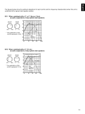
... below show the optimum adjustment of this unit is combined with a 5" (13 cm ) acoustic suspension, 2 way system main speakers HIGH CUT VOLUME dB Combined frequency response 90 80 50 Hz 150 Hz 0 10 70 * One graduation of each control and the frequency characteristics when this control represents 10 Hz. 60 50 40 20 YST-SW45 Main speaker's response 50 100...
... below show the optimum adjustment of this unit is combined with a 5" (13 cm ) acoustic suspension, 2 way system main speakers HIGH CUT VOLUME dB Combined frequency response 90 80 50 Hz 150 Hz 0 10 70 * One graduation of each control and the frequency characteristics when this control represents 10 Hz. 60 50 40 20 YST-SW45 Main speaker's response 50 100...
Owner's Manual
Page 12
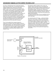
... of great amplitude if the design is used . High-amplitude bass sound Cabinet Port Advanced Negativeimpedance Converter Air woofer (Helmholtz resonator) Active Servo Processing Amplifier Signals Signals of frequencies with the Helmholtz resonator, reproduce an extremely wide range of low amplitude 12 This opening in the speaker's cabinet. By employing negative-impedance drive circuits, the amplifier is a port or opening is such that...
... of great amplitude if the design is used . High-amplitude bass sound Cabinet Port Advanced Negativeimpedance Converter Air woofer (Helmholtz resonator) Active Servo Processing Amplifier Signals Signals of frequencies with the Helmholtz resonator, reproduce an extremely wide range of low amplitude 12 This opening in the speaker's cabinet. By employing negative-impedance drive circuits, the amplifier is a port or opening is such that...
Owner's Manual
Page 13
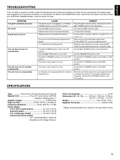
.... Set the AUTO STANDBY switch to right. CAUSE The power cord is not plugged in the SYMPTOM column, disconnect the power cord and contact your authorized YAMAHA dealer or service center for help. Speaker wires are connected incorrectly. It is influenced by placing bookshelves etc. The level of input signal is too low. Connect them securely. SPECIFICATIONS YST-SW45 Type Active Servo Processing Subwoofer System Speaker Unit 20 cm (8") cone woofer (JA2162) magnetic shielding type x 1 Amplifier Output 70 W/5 ohms High...
.... Set the AUTO STANDBY switch to right. CAUSE The power cord is not plugged in the SYMPTOM column, disconnect the power cord and contact your authorized YAMAHA dealer or service center for help. Speaker wires are connected incorrectly. It is influenced by placing bookshelves etc. The level of input signal is too low. Connect them securely. SPECIFICATIONS YST-SW45 Type Active Servo Processing Subwoofer System Speaker Unit 20 cm (8") cone woofer (JA2162) magnetic shielding type x 1 Amplifier Output 70 W/5 ohms High...

Owner's Manual
Page 14
...-BEAUBOURG 77312 MARNE-LA-VALLEE CEDEX02, FRANCE YAMAHA ELECTRONICS (UK) LTD. OF GERMANY YAMAHA ELECTRONIQUE FRANCE S.A. SIEMENSSTR. 22-34, 25462 RELLINGEN BEI HAMBURG, F.R. YAMAHA HOUSE, 200 RICKMANSWORTH ROAD WATFORD, HERTS WD1 7JS, ENGLAND YAMAHA SCANDINAVIA A.B. J A WETTERGRENS GATA 1, BOX 30053, 400 43 VÄSTRA FRÖLUNDA, SWEDEN YAMAHA MUSIC AUSTRALIA PTY, LTD. 17-33 MARKET ST...
...-BEAUBOURG 77312 MARNE-LA-VALLEE CEDEX02, FRANCE YAMAHA ELECTRONICS (UK) LTD. OF GERMANY YAMAHA ELECTRONIQUE FRANCE S.A. SIEMENSSTR. 22-34, 25462 RELLINGEN BEI HAMBURG, F.R. YAMAHA HOUSE, 200 RICKMANSWORTH ROAD WATFORD, HERTS WD1 7JS, ENGLAND YAMAHA SCANDINAVIA A.B. J A WETTERGRENS GATA 1, BOX 30053, 400 43 VÄSTRA FRÖLUNDA, SWEDEN YAMAHA MUSIC AUSTRALIA PTY, LTD. 17-33 MARKET ST...


