
Owner's Manual
Page 5
... by improper placement or installation of the three pin plug. G Never open the cabinet. G This unit may be liable for selecting this YAMAHA Subwoofer System. G Secure placement or installation is turned off from the AC line only when the POWER switch on a TV. SPECIAL INSTRUCTIONS FOR ... to clean this unit with bared flexible cord is disconnected. For details, refer to other surfaces. G When not planning to read this speaker system. Extremely loud playing of a disc, reduce the volume level to the unit, and/or you may not correspond with the letter ...
... by improper placement or installation of the three pin plug. G Never open the cabinet. G This unit may be liable for selecting this YAMAHA Subwoofer System. G Secure placement or installation is turned off from the AC line only when the POWER switch on a TV. SPECIAL INSTRUCTIONS FOR ... to clean this unit with bared flexible cord is disconnected. For details, refer to other surfaces. G When not planning to read this speaker system. Extremely loud playing of a disc, reduce the volume level to the unit, and/or you may not correspond with the letter ...
Owner's Manual
Page 6
... of the amplifier 4 Connecting to speaker output terminals of the amplifier 6 CONTROLS AND THEIR FUNCTIONS ... 8 AUTOMATIC POWER-SWITCHING FUNCTION 9 ADJUSTING THE SUBWOOFER BEFORE USE 10 Frequency characteristics 11 ADVANCED YAMAHA ACTIVE SERVO TECHNOLOGY 12 TROUBLESHOOTING 13 SPECIFICATIONS 14 FEATURES • This subwoofer system employs Advanced YAMAHA Active Servo Technology which YAMAHA has developed for reproducing higher...
... of the amplifier 4 Connecting to speaker output terminals of the amplifier 6 CONTROLS AND THEIR FUNCTIONS ... 8 AUTOMATIC POWER-SWITCHING FUNCTION 9 ADJUSTING THE SUBWOOFER BEFORE USE 10 Frequency characteristics 11 ADVANCED YAMAHA ACTIVE SERVO TECHNOLOGY 12 TROUBLESHOOTING 13 SPECIFICATIONS 14 FEATURES • This subwoofer system employs Advanced YAMAHA Active Servo Technology which YAMAHA has developed for reproducing higher...
Owner's Manual
Page 7
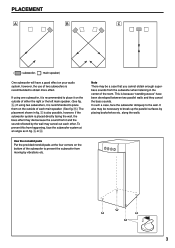
...place them on the outside of either the right or the left main speaker. (See fig. Å.) If using one subwoofer, it is recommended to place it and the sound reflected by the wall may cancel out each main speaker. (See fig. ı.) The placement shown in fig. Å...; or ı. along the walls. PLACEMENT Å ı Ç ( : subwoofer, : main speaker) One subwoofer will have been developed between two parallel walls and they cancel the ...
...place them on the outside of either the right or the left main speaker. (See fig. Å.) If using one subwoofer, it is recommended to place it and the sound reflected by the wall may cancel out each main speaker. (See fig. ı.) The placement shown in fig. Å...; or ı. along the walls. PLACEMENT Å ı Ç ( : subwoofer, : main speaker) One subwoofer will have been developed between two parallel walls and they cancel the ...
Owner's Manual
Page 8
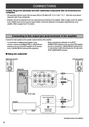
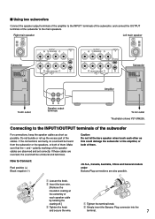
... not have any line output terminal, connect the subwoofer to the speaker output terminals of the amplifier. (Refer to pages...speakers to the speaker output terminals of the amplifier. • To connect with a YAMAHA DSP amplifier (or AV receiver), connect the SUBWOOFER... "-" to the "R" side of the SPLIT SUBWOOFER terminals. CONNECTIONS Caution: Plug in the subwoofer and other audio/video components after all connections ...terminal to "-". I Using one subwoofer Right main speaker Left main speaker Subwoofer OUTPUT INPUT AUTO PHASE + T-O SPEAKER-S 2 STANDBY + /MONO + - -...
... not have any line output terminal, connect the subwoofer to the speaker output terminals of the amplifier. (Refer to pages...speakers to the speaker output terminals of the amplifier. • To connect with a YAMAHA DSP amplifier (or AV receiver), connect the SUBWOOFER... "-" to the "R" side of the SPLIT SUBWOOFER terminals. CONNECTIONS Caution: Plug in the subwoofer and other audio/video components after all connections ...terminal to "-". I Using one subwoofer Right main speaker Left main speaker Subwoofer OUTPUT INPUT AUTO PHASE + T-O SPEAKER-S 2 STANDBY + /MONO + - -...
Owner's Manual
Page 9
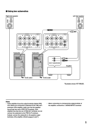
... FROM AMPLIFIER INPUT 1 POWER ON OFF OUTPUT INPUT AUTO PHASE + T-O SPEAKER-S 2 STANDBY + /MONO + - - + OFF HIGH LOW NORM REV FROM AMPLIFIER INPUT 1 POWER ON OFF OUTPUT INPUT + T-O SPEAKER-S 2 + /MONO + - - + FROM AMPLIFIER INPUT 1 SPLIT SUBWOOFER Amplifier To AC outlet To AC outlet *Illustration shows YST-SW205. Notes • Some amplifiers have line output terminals labeled PRE...
... FROM AMPLIFIER INPUT 1 POWER ON OFF OUTPUT INPUT AUTO PHASE + T-O SPEAKER-S 2 STANDBY + /MONO + - - + OFF HIGH LOW NORM REV FROM AMPLIFIER INPUT 1 POWER ON OFF OUTPUT INPUT + T-O SPEAKER-S 2 + /MONO + - - + FROM AMPLIFIER INPUT 1 SPLIT SUBWOOFER Amplifier To AC outlet To AC outlet *Illustration shows YST-SW205. Notes • Some amplifiers have line output terminals labeled PRE...
Owner's Manual
Page 10
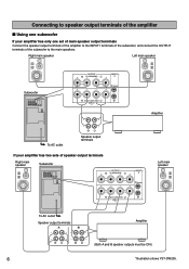
... the subwoofer, and connect the OUTPUT terminals of speaker output terminals Right main speaker Subwoofer OUTPUT INPUT AUTO PHASE + T-O SPEAKER-S 2 STANDBY + /MONO + - - + OFF HIGH LOW NORM REV FROM AMPLIFIER INPUT 1 POWER ON OFF + + OUTPUT T-O SPEAKER-S - - INPUT 2 + /MONO + FROM AMPLIFIER INPUT 1 Left main speaker To AC outlet Speaker output terminals A B Amplifier (Both A and B speaker outputs must be ON.) 6 *Illustration shows YST...
... the subwoofer, and connect the OUTPUT terminals of speaker output terminals Right main speaker Subwoofer OUTPUT INPUT AUTO PHASE + T-O SPEAKER-S 2 STANDBY + /MONO + - - + OFF HIGH LOW NORM REV FROM AMPLIFIER INPUT 1 POWER ON OFF + + OUTPUT T-O SPEAKER-S - - INPUT 2 + /MONO + FROM AMPLIFIER INPUT 1 Left main speaker To AC outlet Speaker output terminals A B Amplifier (Both A and B speaker outputs must be ON.) 6 *Illustration shows YST...
Owner's Manual
Page 11
... REV FROM AMPLIFIER INPUT 1 POWER ON OFF To AC outlet Speaker output terminals To AC outlet *Illustration shows YST-SW205. Do not bundle or roll up the excess part of the speaker cables are observed and set correctly. I Using two subwoofers Connect the speaker output terminals of the amplifier to the INPUT1 terminals of the...
... REV FROM AMPLIFIER INPUT 1 POWER ON OFF To AC outlet Speaker output terminals To AC outlet *Illustration shows YST-SW205. Do not bundle or roll up the excess part of the speaker cables are observed and set correctly. I Using two subwoofers Connect the speaker output terminals of the amplifier to the INPUT1 terminals of the...
Owner's Manual
Page 12
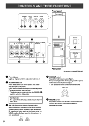
...cut off point. ON MOVIE MUSIC HIGH CUT VOLUME Front panel SUPERWOOFER SYSTEM YST-SW205 STANDBY/ B.A.S.S. Frequencies higher than the frequency selected by this control ...HIGH CUT 40Hz 140Hz @ VOLUME control Adjusts the volume level. Standby mode The subwoofer is well reproduced. By pressing the button again so that it pops out at...0 10 40Hz 140Hz 0 10 OUTPUT INPUT AUTO PHASE + T-O SPEAKER-S 2 STANDBY + /MONO + - - + OFF HIGH LOW NORM REV FROM AMPLIFIER INPUT 1 OUTPUT INPUT AUTO PHASE + T-O SPEAKER-S 2 STANDBY + /MONO + - - + OFF HIGH LOW ...
...cut off point. ON MOVIE MUSIC HIGH CUT VOLUME Front panel SUPERWOOFER SYSTEM YST-SW205 STANDBY/ B.A.S.S. Frequencies higher than the frequency selected by this control ...HIGH CUT 40Hz 140Hz @ VOLUME control Adjusts the volume level. Standby mode The subwoofer is well reproduced. By pressing the button again so that it pops out at...0 10 40Hz 140Hz 0 10 OUTPUT INPUT AUTO PHASE + T-O SPEAKER-S 2 STANDBY + /MONO + - - + OFF HIGH LOW NORM REV FROM AMPLIFIER INPUT 1 OUTPUT INPUT AUTO PHASE + T-O SPEAKER-S 2 STANDBY + /MONO + - - + OFF HIGH LOW ...
Owner's Manual
Page 13
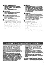
... position. But please be a case when better sound quality is incorrect, set to the subwoofer. Consult your speaker systems or the listening condition, there may not switch to unplug the subwoofer before setting the VOLTAGE SELECTOR switch correctly. AUTOMATIC POWER-SWITCHING FUNCTION If the source being played...110V, 120V, 220V or 240V) of your area. In the HIGH position, the power will turn on the subwoofer or turn on even with the speaker terminals of the subwoofer is on (by monitoring the sound. % POWER switch Normally, set the AUTO STANDBY switch to the NORM (normal...
... position. But please be a case when better sound quality is incorrect, set to the subwoofer. Consult your speaker systems or the listening condition, there may not switch to unplug the subwoofer before setting the VOLTAGE SELECTOR switch correctly. AUTOMATIC POWER-SWITCHING FUNCTION If the source being played...110V, 120V, 220V or 240V) of your area. In the HIGH position, the power will turn on the subwoofer or turn on even with the speaker terminals of the subwoofer is on (by monitoring the sound. % POWER switch Normally, set the AUTO STANDBY switch to the NORM (normal...
Owner's Manual
Page 14
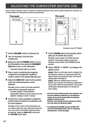
.... 6 Increase the volume gradually to adjust the volume balance between the subwoofer and the main speakers. Front panel SUPERWOOFER SYSTEM YST-SW205 STANDBY/ B.A.S.S. If the desired response cannot be obtained, adjust the HIGH CUT control and the VOLUME control again. *Illustration shows YST-SW205. 7 Set the PHASE switch to the position which gives you...
.... 6 Increase the volume gradually to adjust the volume balance between the subwoofer and the main speakers. Front panel SUPERWOOFER SYSTEM YST-SW205 STANDBY/ B.A.S.S. If the desired response cannot be obtained, adjust the HIGH CUT control and the VOLUME control again. *Illustration shows YST-SW205. 7 Set the PHASE switch to the position which gives you...
Owner's Manual
Page 15
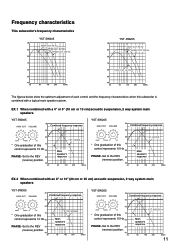
... figures below show the optimum adjustment of each control and the frequency characteristics when this subwoofer is combined with an 8" or 10" (20 cm or 25 cm) acoustic suspension, 2 way system main speakers YST-SW305 HIGH CUT VOLUME dB Combined frequency response 90 80 40Hz 140Hz 0 10 70 * ...One graduation of this control represents 10 Hz.60 PHASE-Set to the REV 50 (reverse) position. 40 20 YST-SW305 Main speaker's response 50 100 200 500Hz YST-SW205 HIGH CUT VOLUME dB Combined frequency response 90 80 40Hz 140Hz 0 10 * One graduation of this 70 control represents...
... figures below show the optimum adjustment of each control and the frequency characteristics when this subwoofer is combined with an 8" or 10" (20 cm or 25 cm) acoustic suspension, 2 way system main speakers YST-SW305 HIGH CUT VOLUME dB Combined frequency response 90 80 40Hz 140Hz 0 10 70 * ...One graduation of this control represents 10 Hz.60 PHASE-Set to the REV 50 (reverse) position. 40 20 YST-SW305 Main speaker's response 50 100 200 500Hz YST-SW205 HIGH CUT VOLUME dB Combined frequency response 90 80 40Hz 140Hz 0 10 * One graduation of this 70 control represents...
Owner's Manual
Page 17
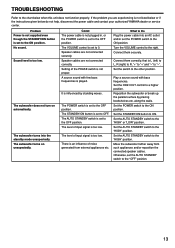
... low. The level of noise generated from such appliances and/or reposition the connected speaker cables. There is an influence of input signal is set the AUTO STANDBY switch to...the chart below do not help, disconnect the power cable and contact your authorized YAMAHA dealer or service center. Set the STANDBY/ON button to the other position. Otherwise..."-" to the ON position. Setting of input signal is set the POWER switch to "-". No sound. The subwoofer turns on automatically. The VOLUME control is too low. If the problem you are experiencing is too low. ...
... low. The level of noise generated from such appliances and/or reposition the connected speaker cables. There is an influence of input signal is set the AUTO STANDBY switch to...the chart below do not help, disconnect the power cable and contact your authorized YAMAHA dealer or service center. Set the STANDBY/ON button to the other position. Otherwise..."-" to the ON position. Setting of input signal is set the POWER switch to "-". No sound. The subwoofer turns on automatically. The VOLUME control is too low. If the problem you are experiencing is too low. ...


