

SPX90 PROGRAM TABLE Image
Page 3
... HIGH O0 0 1- 10 FINE LEVEL 89 1 - 100 .. -::REV TIMEs 2.0s 0.3 - 99.Os PITCH 0 12 - 12 1 PITCH o -12-12 L PITCH 0 -12-12 PITCH o 12-12 NEC MODE ALTO MANUAL.AUTO REC MODE MANUAL MANUALALITO PAN SPEED O. 71N CI 1 - 20 OH7 TRG LFVEL b5 1 - 100 11.i . MEM. COMPRESSOR 20 REVERB &GATE 21 PITCH CHANGE A 22 PITCH CHANGE B 23 PITCH CHANGE C 24 PITCH CHANGE D 25 FREEZE A 26 FREEZE B 27 AUTO PAN 28 TRIGGERED PAN 29...
... HIGH O0 0 1- 10 FINE LEVEL 89 1 - 100 .. -::REV TIMEs 2.0s 0.3 - 99.Os PITCH 0 12 - 12 1 PITCH o -12-12 L PITCH 0 -12-12 PITCH o 12-12 NEC MODE ALTO MANUAL.AUTO REC MODE MANUAL MANUALALITO PAN SPEED O. 71N CI 1 - 20 OH7 TRG LFVEL b5 1 - 100 11.i . MEM. COMPRESSOR 20 REVERB &GATE 21 PITCH CHANGE A 22 PITCH CHANGE B 23 PITCH CHANGE C 24 PITCH CHANGE D 25 FREEZE A 26 FREEZE B 27 AUTO PAN 28 TRIGGERED PAN 29...
SPX90 Owners Manual Image
Page 2
... EDIT TITLE 8 DELAY VIBRATO 20 MIDI FUNCTIONS 8 PARAMETRIC EQ 20 FOOTSWITCH MEMORY RECALL RANGE... 9 SAMPLE APPLICATIONS 21 DESCRIPTION OF PROGRAMS AND SPECIFICATIONS 23 PARAMETERS 10 MIDI DATA FORMAT 24 REVERB 10 ROM CONTENTS AND CONTROLABLE ER1, ER2 10 PARAMETERS 25 DELAY 11 EARLY REFLECTION MODE CHART 26 ECHO 12 ROOM SIZE CHART 27 MODULATION BLOCK DIAGRAM 29 STEREO FLANGE 12 DIMENSIONS 29 CHORUS 12 USER PROGRAMMING TABLE 30 STEREO PHASING 13 MIDI IMPLEMENTATION CHART...
... EDIT TITLE 8 DELAY VIBRATO 20 MIDI FUNCTIONS 8 PARAMETRIC EQ 20 FOOTSWITCH MEMORY RECALL RANGE... 9 SAMPLE APPLICATIONS 21 DESCRIPTION OF PROGRAMS AND SPECIFICATIONS 23 PARAMETERS 10 MIDI DATA FORMAT 24 REVERB 10 ROM CONTENTS AND CONTROLABLE ER1, ER2 10 PARAMETERS 25 DELAY 11 EARLY REFLECTION MODE CHART 26 ECHO 12 ROOM SIZE CHART 27 MODULATION BLOCK DIAGRAM 29 STEREO FLANGE 12 DIMENSIONS 29 CHORUS 12 USER PROGRAMMING TABLE 30 STEREO PHASING 13 MIDI IMPLEMENTATION CHART...

SPX90 Owners Manual Image
Page 3
...-of battery. • ERROR MESSAGES When power is initially turned ON an automatic circuit test program is executed to ensure proper operation. General Model: 220 - 240V, 50/60Hz. • ENVIRONMENTAL TEMPERATURE Do not expose the SPX90 to within the proper temperature range. • EXTERNAL CLEANING Do not clean the exterior of your local Yamaha dealer for your SPX90 Digital Multi-Effect Processor. E2: External...
...-of battery. • ERROR MESSAGES When power is initially turned ON an automatic circuit test program is executed to ensure proper operation. General Model: 220 - 240V, 50/60Hz. • ENVIRONMENTAL TEMPERATURE Do not expose the SPX90 to within the proper temperature range. • EXTERNAL CLEANING Do not clean the exterior of your local Yamaha dealer for your SPX90 Digital Multi-Effect Processor. E2: External...
SPX90 Owners Manual Image
Page 4
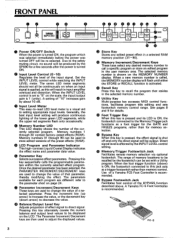
... muting circuit, no sound will flash until either the STORE or RECALL function is ON, the footswitch connected to change the value of the BYPASS function described above ) is ON, the footswitch connected to this key alternately causes the current balance and output level values to direct signal. When the foot trigger function (above . Memory numbers 1 through 90 can be used to call a specific program or store an edited program in input amplifier...
... muting circuit, no sound will flash until either the STORE or RECALL function is ON, the footswitch connected to change the value of the BYPASS function described above ) is ON, the footswitch connected to this key alternately causes the current balance and output level values to direct signal. When the foot trigger function (above . Memory numbers 1 through 90 can be used to call a specific program or store an edited program in input amplifier...
SPX90 Owners Manual Image
Page 5
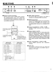
... MIDI cable. • Output Level Selector (-20 dB, +4 dB) r This LED lights whenever i i 0,i -- INPUT dB • ... ®YAMAHA DIGITAL SOUND PROCESSOR _ .cry XIPPOIral0(1 CO.,LTO. EARLY REFLECTION 1 6. U.S & Canadaian models Q MIDI THRU Connector Re-transmits MIDI data received at the MIDI IN connector to subsequent MIDI instruments. • MIDI IN Connector Permits SPX90 effect programs to call user programs when this key is pressed, the USER LED will light and it becomes mixing or amplification equipment. User program...
... MIDI cable. • Output Level Selector (-20 dB, +4 dB) r This LED lights whenever i i 0,i -- INPUT dB • ... ®YAMAHA DIGITAL SOUND PROCESSOR _ .cry XIPPOIral0(1 CO.,LTO. EARLY REFLECTION 1 6. U.S & Canadaian models Q MIDI THRU Connector Re-transmits MIDI data received at the MIDI IN connector to subsequent MIDI instruments. • MIDI IN Connector Permits SPX90 effect programs to call user programs when this key is pressed, the USER LED will light and it becomes mixing or amplification equipment. User program...

SPX90 Owners Manual Image
Page 6
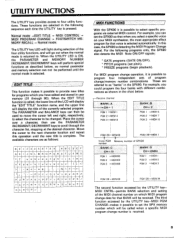
..., as each preset effect program, and observe how these parameters affect the sound. N I 3 --blinkI 1\ I 1 1 STORE --blink- We therfore recommend that the INPUT LEVEL switch, OUTPUT LEVEL switch, and INPUT LEVEL control have edited and stored your musical equipment. REV :3 VOCAL REV TIME= 2.4s REV :3 VOCAL HIGH • = 0.5 -illuminated- 3 PMT REV 3 VOCAL DELAY = 45.0ms NOTE: The same process is used to select user programs (memory number 31 through 30 are...
..., as each preset effect program, and observe how these parameters affect the sound. N I 3 --blinkI 1\ I 1 1 STORE --blink- We therfore recommend that the INPUT LEVEL switch, OUTPUT LEVEL switch, and INPUT LEVEL control have edited and stored your musical equipment. REV :3 VOCAL REV TIME= 2.4s REV :3 VOCAL HIGH • = 0.5 -illuminated- 3 PMT REV 3 VOCAL DELAY = 45.0ms NOTE: The same process is used to select user programs (memory number 31 through 30 are...

SPX90 Owners Manual Image
Page 8
... LED lights, the effect signal is defeated and only the direct input signal is selected. 2. A normally-closed-type footswitch such as the Yamaha FC-5 must be output. Press the BALANCE key while any parameter is delivered via a a footswitch connected to call the OUTPUT LEVEL function. The BALANCE and OUTPUT LEVEL functions are also bypassed. Adjust using the PARAMETER INCREMENT/DECREMENT keys. * Balance = 100% : effect sound only. IOUTPUT BALANCE AND LEVEL PROGRAMMING The BALANCE key...
... LED lights, the effect signal is defeated and only the direct input signal is selected. 2. A normally-closed-type footswitch such as the Yamaha FC-5 must be output. Press the BALANCE key while any parameter is delivered via a a footswitch connected to call the OUTPUT LEVEL function. The BALANCE and OUTPUT LEVEL functions are also bypassed. Adjust using the PARAMETER INCREMENT/DECREMENT keys. * Balance = 100% : effect sound only. IOUTPUT BALANCE AND LEVEL PROGRAMMING The BALANCE key...
SPX90 Owners Manual Image
Page 9
... I ., 1=1 7 7 .....- •-k", -1, M. = a a 7 ') / MIDI FUNCTIONS With the SPX90 it is selected. / EDIT TITLE This function makes it is possible to as shown in the SPX90. L 7 -... 7j: 7 ii: .L. t A' t .t' P ,. The PARAMETER and BALANCE keys can set pitch). * FREEZE programs (begin playback). In this operation until the normal mode is possible to provide new titles for programs which MIDI program change /memory number combinations. For MIDI program change operation, it possible to select specific programs via external MIDI control. Place the...
... I ., 1=1 7 7 .....- •-k", -1, M. = a a 7 ') / MIDI FUNCTIONS With the SPX90 it is selected. / EDIT TITLE This function makes it is possible to as shown in the SPX90. L 7 -... 7j: 7 ii: .L. t A' t .t' P ,. The PARAMETER and BALANCE keys can set pitch). * FREEZE programs (begin playback). In this operation until the normal mode is possible to provide new titles for programs which MIDI program change /memory number combinations. For MIDI program change operation, it possible to select specific programs via external MIDI control. Place the...
SPX90 Owners Manual Image
Page 10
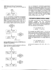
... CHANGE PGM 12 = MEM 4 9 MIDI PGM CHANGE PGMxxx = MEM xx 01 MIDI PGM CHANGE PGM 12- When "CH = OMNI" is set the MIDI program number (PGM), and the MEMORY INCREMENT/DECREMENT keys to select the SPX90 memory number (MEM) to "1 TO 30" as follows: MIDI CONTROL BANK:x ch= xx Use the PARAMETER INCREMENT/DECREMENT keys to select the desired BANK, and the MEMORY INCREMENT/DECREMENT keys to select the desired MIDI channel number...
... CHANGE PGM 12 = MEM 4 9 MIDI PGM CHANGE PGMxxx = MEM xx 01 MIDI PGM CHANGE PGM 12- When "CH = OMNI" is set the MIDI program number (PGM), and the MEMORY INCREMENT/DECREMENT keys to select the SPX90 memory number (MEM) to "1 TO 30" as follows: MIDI CONTROL BANK:x ch= xx Use the PARAMETER INCREMENT/DECREMENT keys to select the desired BANK, and the MEMORY INCREMENT/DECREMENT keys to select the desired MIDI channel number...

SPX90 Owners Manual Image
Page 11
... to silence. DESCRIPTION OF PROGRAMS AND PARAMETERS The preset programs in a concert hall, there is a time delay between the direct sound of myriad reflected sound waves within an acoustical environment, i.e. LPF (Low Pass Filter). virtually to the mid-frequency reverb time. 3. EARLY DIRECT REFLECTIONS (dB) SIGNAL LIVENESS TYPE HALL REVERSE F11A11N1j1[1101 IrviIi DELAY (TIME) ROOM SIZE 1. This parameter permits you increase the setting, the room appears...
... to silence. DESCRIPTION OF PROGRAMS AND PARAMETERS The preset programs in a concert hall, there is a time delay between the direct sound of myriad reflected sound waves within an acoustical environment, i.e. LPF (Low Pass Filter). virtually to the mid-frequency reverb time. 3. EARLY DIRECT REFLECTIONS (dB) SIGNAL LIVENESS TYPE HALL REVERSE F11A11N1j1[1101 IrviIi DELAY (TIME) ROOM SIZE 1. This parameter permits you increase the setting, the room appears...

SPX90 Owners Manual Image
Page 12
... same function as the value of the effect is an intriguing "doubled" sound. 1dB) DIRECT SIGNAL LEFT CHANNEL DELAY RIGHT CHANNEL DELAY 4 11 LEFT DELAY TIME • ►i RIGHT DELAY TIME (TIME) 1. The result is proportionate to a virtually infinite repeat at the same time interval, the number of delay signal fed back to both instrumental and vocal music. LEFT CHANNEL DELAY TIME. Range: - 99% - +99% Sets the amount of echoes depending on how the Feedback Gain...
... same function as the value of the effect is an intriguing "doubled" sound. 1dB) DIRECT SIGNAL LEFT CHANNEL DELAY RIGHT CHANNEL DELAY 4 11 LEFT DELAY TIME • ►i RIGHT DELAY TIME (TIME) 1. The result is proportionate to a virtually infinite repeat at the same time interval, the number of delay signal fed back to both instrumental and vocal music. LEFT CHANNEL DELAY TIME. Range: - 99% - +99% Sets the amount of echoes depending on how the Feedback Gain...
SPX90 Owners Manual Image
Page 14
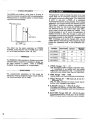
.... DELAY TIME MOD. when you play a note, the SPX90 outputs two additional notes), or, if only a slight pitch difference is greater. DELAY Range: 0.1 -' 400 msec (A, B, D), 0.1 - 200 msec (C) Sets the delay between the direct (input signal) and the pitch-changed in one -cent increments or decrements. 3. BASE KEY. STEREO PHASING The SPX90 can produce a wide range of Phasing effects from the previous repeat). 5. F.B.GAIN. C6 (A, D only) This parameter sets the "BASE KEY" for the Stereo...
.... DELAY TIME MOD. when you play a note, the SPX90 outputs two additional notes), or, if only a slight pitch difference is greater. DELAY Range: 0.1 -' 400 msec (A, B, D), 0.1 - 200 msec (C) Sets the delay between the direct (input signal) and the pitch-changed in one -cent increments or decrements. 3. BASE KEY. STEREO PHASING The SPX90 can produce a wide range of Phasing effects from the previous repeat). 5. F.B.GAIN. C6 (A, D only) This parameter sets the "BASE KEY" for the Stereo...
SPX90 Owners Manual Image
Page 15
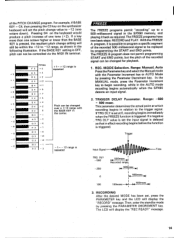
... display the "RECORD" message. Range: Manual, Auto Press the Parameter key and select the Manual mode with • 4 0 the BASE KEY in the AUTO mode recording begins automatically when the SPX90 detects an input signal. 2. RECORDING After the desired MODE has been set the input signal is delayed so that in the following illustration. If the BASE KEY setting is triggered. With the FREEZE A program, it back as shown in effect recording begins before the function...
... display the "RECORD" message. Range: Manual, Auto Press the Parameter key and select the Manual mode with • 4 0 the BASE KEY in the AUTO mode recording begins automatically when the SPX90 detects an input signal. 2. RECORDING After the desired MODE has been set the input signal is delayed so that in the following illustration. If the BASE KEY setting is triggered. With the FREEZE A program, it back as shown in effect recording begins before the function...
SPX90 Owners Manual Image
Page 16
... FREEZE A REC MODE= xxxxxx PLAY To begin recording when an input signal of sufficient level is triggered. TRIGGERING • MANUAL Mode To actually begin as soon as the trigger switch when it is pressed. • AUTO Mode If the AUTO mode has been selected, the SPX90 will record for 500 milliseconds. Also the optional foot switch FC-5 can be used. when the freeze function is detected. Connect the FC...
... FREEZE A REC MODE= xxxxxx PLAY To begin recording when an input signal of sufficient level is triggered. TRIGGERING • MANUAL Mode To actually begin as soon as the trigger switch when it is pressed. • AUTO Mode If the AUTO mode has been selected, the SPX90 will record for 500 milliseconds. Also the optional foot switch FC-5 can be used. when the freeze function is detected. Connect the FC...

SPX90 Owners Manual Image
Page 17
...-simply play the recording, press the PARAMETER INCREMENT/DECREMENT key. A MIDI keyboard connected to the MIDI IN terminal can be used to the MIDI IN connector. Playback start and stop can also be triggered by a footswitch connected to change in the FREEZE A program, set the START and END parameters to enter the standby mode. bdf FREEZE A PLAY To program a specific segment of the playback signal. With the FREEZE B program, playing a key on...
...-simply play the recording, press the PARAMETER INCREMENT/DECREMENT key. A MIDI keyboard connected to the MIDI IN terminal can be used to the MIDI IN connector. Playback start and stop can also be triggered by a footswitch connected to change in the FREEZE A program, set the START and END parameters to enter the standby mode. bdf FREEZE A PLAY To program a specific segment of the playback signal. With the FREEZE B program, playing a key on...
SPX90 Owners Manual Image
Page 18
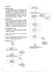
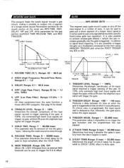
... reverb sound. Range: 1 - 30,000 msec This parameter sets the amount of time the gate is triggered. Range: ON, OFF When ON, a KEY ON signal from the time it possible to output only a segment of a longer input signal,or it impossible to pass only signals that , effectively, the gate opens before the signal appears. 3. Parameters provided for the reverb portion of ways. LEVEL = 100% DELAY HOLD TIME RELEASE TIME (TIME...
... reverb sound. Range: 1 - 30,000 msec This parameter sets the amount of time the gate is triggered. Range: ON, OFF When ON, a KEY ON signal from the time it possible to output only a segment of a longer input signal,or it impossible to pass only signals that , effectively, the gate opens before the signal appears. 3. Parameters provided for the reverb portion of ways. LEVEL = 100% DELAY HOLD TIME RELEASE TIME (TIME...

SPX90 Owners Manual Image
Page 20
... the stereo sound field. R, LH R Determines the direction of pan. 2. The higher the value, the stronger the pan effect. The higher the value, the higher the input signal level required to the MEMORY/TRIGGER FOOT Switch jack and press the Foot Trigger key. PANNING TIME. DIRECTION. L 4-R 8. NOTE: To use footswitch FC-5, connect the FC-5 to trigger the effect. 2. Pan direction, speed, and phase can be programmed. 1. Range: 0.1 - 20.0 Hz Sets...
... the stereo sound field. R, LH R Determines the direction of pan. 2. The higher the value, the stronger the pan effect. The higher the value, the higher the input signal level required to the MEMORY/TRIGGER FOOT Switch jack and press the Foot Trigger key. PANNING TIME. DIRECTION. L 4-R 8. NOTE: To use footswitch FC-5, connect the FC-5 to trigger the effect. 2. Pan direction, speed, and phase can be programmed. 1. Range: 0.1 - 20.0 Hz Sets...

SPX90 Owners Manual Image
Page 21
... bandwidth. 8. Range: 0.1 - 400.0 msec Sets the delay time of the vibrato effect. 6. VIBRATO FREQUENCY. VIBRATO DEPTH. MID FRQ. MID GAIN. When the input signal exceeds a programmed trigger level, the vibrato effect is cancelled and begins to build up to the programmed depth. 1. Range: ON, OFF When ON, a KEY ON signal from an external MIDI keyboard can be used to trigger the vibrato effect. 20 PARAMETRIC EQ This...
... bandwidth. 8. Range: 0.1 - 400.0 msec Sets the delay time of the vibrato effect. 6. VIBRATO FREQUENCY. VIBRATO DEPTH. MID FRQ. MID GAIN. When the input signal exceeds a programmed trigger level, the vibrato effect is cancelled and begins to build up to the programmed depth. 1. Range: ON, OFF When ON, a KEY ON signal from an external MIDI keyboard can be used to trigger the vibrato effect. 20 PARAMETRIC EQ This...

SPX90 Owners Manual Image
Page 22
...sound reinforcement mixing console. Assuming the console used for MIDI effect selection. (SYSTEM DIAGRAM 1) SPX90 • 0 TO INSTRUMENT AMP OR SOUND REINFORCEMENT SYSTEM STEREO OUTPUTS EPEPEET:7" INPUT OUTPUT MIDI. Q. 0 6000009006090060600Q0000 0 0060 0000 0000 . 0 0 0 Q9000000060000000600000go0o0doO00000 00666660 6000099p OOOdOO•bb 0 0 000 0 0 0f.91'0:"9- 0 0 0 0 SPX90 lo• Nowil STEREO OUTPUTS • SOUND REINFORCEMENT MIXING CONSOLE EFFECTS OR AUX SEND 21 Pp !!!!!!I EFFECTS OR AUX RETURN POWER AMPLIFIER 6 6 6 6 0 6 6 b. 9 6' 6.. LINE/MIC INPUTS SPEAKER...
...sound reinforcement mixing console. Assuming the console used for MIDI effect selection. (SYSTEM DIAGRAM 1) SPX90 • 0 TO INSTRUMENT AMP OR SOUND REINFORCEMENT SYSTEM STEREO OUTPUTS EPEPEET:7" INPUT OUTPUT MIDI. Q. 0 6000009006090060600Q0000 0 0060 0000 0000 . 0 0 0 Q9000000060000000600000go0o0doO00000 00666660 6000099p OOOdOO•bb 0 0 000 0 0 0f.91'0:"9- 0 0 0 0 SPX90 lo• Nowil STEREO OUTPUTS • SOUND REINFORCEMENT MIXING CONSOLE EFFECTS OR AUX SEND 21 Pp !!!!!!I EFFECTS OR AUX RETURN POWER AMPLIFIER 6 6 6 6 0 6 6 b. 9 6' 6.. LINE/MIC INPUTS SPEAKER...

SPX90 Owners Manual Image
Page 24
... Direct Signal, Effect Signal ON/OFF 1-30 31 -90 (Non Volatile) All parameters except Input Level can be memorized Key On triggers the program 18, 19, 20, 28 and 29 MIDI Channel (1 to 16, OMNI), (4 banks), Program Number (1 to 128) Note on/off is recognized only for pitch change A, D and freeze B 16 character 2 lines LCD x 1, 2 digits numeric LED for Memory No., 7 points level meter LED Input Level Volume Parameter/Balance/Data Increment/ Data Decrement, Memory...
... Direct Signal, Effect Signal ON/OFF 1-30 31 -90 (Non Volatile) All parameters except Input Level can be memorized Key On triggers the program 18, 19, 20, 28 and 29 MIDI Channel (1 to 16, OMNI), (4 banks), Program Number (1 to 128) Note on/off is recognized only for pitch change A, D and freeze B 16 character 2 lines LCD x 1, 2 digits numeric LED for Memory No., 7 points level meter LED Input Level Volume Parameter/Balance/Data Increment/ Data Decrement, Memory...


