
Owner's Manual
Page 2
...instructions, and should not be followed. 5 Cleaning - in the literature accompanying the appliance. 1 Read Instructions - Any mounting of overhead power lines or other hazards. This product should be operated only from the product. 14 Lightning - An outside antenna system, extreme care should ...extension cords, or integral convenience receptacles as opening or removing covers may cause the product and cart combination to keep from battery power, or other ). Do not attempt to service this product from the wall outlet and refer servicing to qualified service personnel under...
...instructions, and should not be followed. 5 Cleaning - in the literature accompanying the appliance. 1 Read Instructions - Any mounting of overhead power lines or other hazards. This product should be operated only from the product. 14 Lightning - An outside antenna system, extreme care should ...extension cords, or integral convenience receptacles as opening or removing covers may cause the product and cart combination to keep from battery power, or other ). Do not attempt to service this product from the wall outlet and refer servicing to qualified service personnel under...

Owner's Manual
Page 3
...GROUND CLAMP ELECTRIC SERVICE EQUIPMENT NEC - Failure to follow instructions could void your use only high quality shielded cables. Utilize power outlets that are required, be sure the service technician has used replacement parts specified by the manufacturer or have the same ...connection to an antenna discharge unit, size of grounding conductors, location of interference, which can not locate the appropriate retailer, please contact Yamaha Electronics Corp., U.S.A. 6660 Orangethorpe Ave., Buena Park, CA 90620. d) If the product does not operate normally by following measures: ...
...GROUND CLAMP ELECTRIC SERVICE EQUIPMENT NEC - Failure to follow instructions could void your use only high quality shielded cables. Utilize power outlets that are required, be sure the service technician has used replacement parts specified by the manufacturer or have the same ...connection to an antenna discharge unit, size of grounding conductors, location of interference, which can not locate the appropriate retailer, please contact Yamaha Electronics Corp., U.S.A. 6660 Orangethorpe Ave., Buena Park, CA 90620. d) If the product does not operate normally by following measures: ...

Owner's Manual
Page 4
...) to prevent condensation inside this unit rises, it may overheat, possibly causing damage. 9 Do not use this unit upside-down. Contact qualified Yamaha service personnel when any service is called the standby mode. WARNING TO REDUCE THE RISK OF FIRE OR ELECTRIC SHOCK, DO NOT EXPOSE THIS UNIT...Class B digital apparatus complies with a higher voltage than specified. 13 To prevent damage by STANDBY/ON. IMPORTANT Please record the serial number of power. candles), as they may fall onto this unit and/or this unit may cause fire, damage to this unit. 6 Do not cover this...
...) to prevent condensation inside this unit rises, it may overheat, possibly causing damage. 9 Do not use this unit upside-down. Contact qualified Yamaha service personnel when any service is called the standby mode. WARNING TO REDUCE THE RISK OF FIRE OR ELECTRIC SHOCK, DO NOT EXPOSE THIS UNIT...Class B digital apparatus complies with a higher voltage than specified. 13 To prevent damage by STANDBY/ON. IMPORTANT Please record the serial number of power. candles), as they may fall onto this unit and/or this unit may cause fire, damage to this unit. 6 Do not cover this...

Owner's Manual
Page 5
... 46 Controlling iPod 46 Recording 48 3 About this manual • y indicates a tip for the information about each position of the parts on the power and press SCENE 1 button 8 What do you want to production. In case the button names differ between the manual and product, the product has .... English 1 En and Canada models only 13 Information on jacks and cable plugs 14 Connecting video components 15 Connecting audio components 17 Connecting a Yamaha iPod universal dock 18 Using the VIDEO AUX jacks on the front panel .... 18 Connecting the FM and AM antennas 19 Connecting the...
... 46 Controlling iPod 46 Recording 48 3 About this manual • y indicates a tip for the information about each position of the parts on the power and press SCENE 1 button 8 What do you want to production. In case the button names differ between the manual and product, the product has .... English 1 En and Canada models only 13 Information on jacks and cable plugs 14 Connecting video components 15 Connecting audio components 17 Connecting a Yamaha iPod universal dock 18 Using the VIDEO AUX jacks on the front panel .... 18 Connecting the FM and AM antennas 19 Connecting the...

Owner's Manual
Page 6
... SCENE select function ◆ Preset SCENE templates for various situations ◆ SCENE template customizing capability Decoders and DSP circuits ◆ Proprietary Yamaha technology for discrete multi-channel input ◆ OSD (on-screen display) menus that allow you to avoid prolonged exposure from Dolby Laboratories...decoder to play back the XM HD content of XM Satellite Radio broadcasts in multi-channels, resulting in 5-channel power amplifier ◆ Minimum RMS output power [U.S.A. "SILENT CINEMA" is a trademark of a high-quality stereo ◆ Dolby Digital decoder ◆ Dolby...
... SCENE select function ◆ Preset SCENE templates for various situations ◆ SCENE template customizing capability Decoders and DSP circuits ◆ Proprietary Yamaha technology for discrete multi-channel input ◆ OSD (on-screen display) menus that allow you to avoid prolonged exposure from Dolby Laboratories...decoder to play back the XM HD content of XM Satellite Radio broadcasts in multi-channels, resulting in 5-channel power amplifier ◆ Minimum RMS output power [U.S.A. "SILENT CINEMA" is a trademark of a high-quality stereo ◆ Dolby Digital decoder ◆ Dolby...

Owner's Manual
Page 7
...General models only) Caution The VOLTAGE SELECTOR on the inside of the memory may cause damage to your local voltage BEFORE plugging the power cable into contact with general house waste; Notes • Change all of the following conditions: - Read the packaging carefully as... INTRODUCTION Getting started Getting started ■ Checking the supplied accessories Check that you received all of the batteries if you notice the following parts. Remote control CODE SET TRANSMIT POWER TV POWER AV STANDBY POWER CD DVD DOCK V-AUX MD CD-R CBL DTV MULTI CH IN AUDIO SEL...
...General models only) Caution The VOLTAGE SELECTOR on the inside of the memory may cause damage to your local voltage BEFORE plugging the power cable into contact with general house waste; Notes • Change all of the following conditions: - Read the packaging carefully as... INTRODUCTION Getting started Getting started ■ Checking the supplied accessories Check that you received all of the batteries if you notice the following parts. Remote control CODE SET TRANSMIT POWER TV POWER AV STANDBY POWER CD DVD DOCK V-AUX MD CD-R CBL DTV MULTI CH IN AUDIO SEL...

Owner's Manual
Page 8
... projector equipped with a composite video input jack. ❏ Video cable 1 Select an RCA composite video cable. ❏ Digital coaxial audio cable 1 Step 3: Turn on the power and press SCENE 1 button ☞ P. 8 Enjoy DVD playback! 4 En
... projector equipped with a composite video input jack. ❏ Video cable 1 Select an RCA composite video cable. ❏ Digital coaxial audio cable 1 Step 3: Turn on the power and press SCENE 1 button ☞ P. 8 Enjoy DVD playback! 4 En

Owner's Manual
Page 11
INTRODUCTION 4 Connect the FM and AM antennas to AM and GND terminal. 5 Connect the power plug of speaker combinations ☞ P. 12 • Connecting a video monitor ☞ P. 15, 16 • Connecting a DVD player ☞ P. 15, 16 • Connecting a DVD recorder ...; Connecting a CD player and an MD recorder ☞ P. 17 • Connecting a DVD player via analog multi-channel audio connection ☞ P. 17 • Connecting a Yamaha iPod universal dock ☞ P. 18 • Using the VIDEO AUX jacks on the front panel ☞ P. 18 • Connecting an outdoor FM/AM antenna ☞...
INTRODUCTION 4 Connect the FM and AM antennas to AM and GND terminal. 5 Connect the power plug of speaker combinations ☞ P. 12 • Connecting a video monitor ☞ P. 15, 16 • Connecting a DVD player ☞ P. 15, 16 • Connecting a DVD recorder ...; Connecting a CD player and an MD recorder ☞ P. 17 • Connecting a DVD player via analog multi-channel audio connection ☞ P. 17 • Connecting a Yamaha iPod universal dock ☞ P. 18 • Using the VIDEO AUX jacks on the front panel ☞ P. 18 • Connecting an outdoor FM/AM antenna ☞...

Owner's Manual
Page 12
... your player. 5 Rotate 8VOLUME to adjust the volume. 1 Turn on the video monitor connected to watch a TV program..." Quick start guide Step 3: Turn on the power and press SCENE 1 button Check the type of the desired sources. If the speakers are 6 ohm speakers, set "SP IMP."
... your player. 5 Rotate 8VOLUME to adjust the volume. 1 Turn on the video monitor connected to watch a TV program..." Quick start guide Step 3: Turn on the power and press SCENE 1 button Check the type of the desired sources. If the speakers are 6 ohm speakers, set "SP IMP."

Owner's Manual
Page 13
...direct mode for the high fidelity sound ☞ P. 32 • Customizing the sound field programs ☞ P. 37 This unit is set to receive infrared signals from the standby mode, press 1STANDBY/ ON (or GSTANDBY). INTRODUCTION Case C: "I want to do you can select and change the assigned ...☞ P. 64 ■ Additional features Automatically turning off this unit consumes a small amount of power in advance. See page 26 for details. ■ After using this unit consumes a small amount of power in order to the standby mode. Press FSCENE 4 (or FSCENE 4) to 40 for details. ...
...direct mode for the high fidelity sound ☞ P. 32 • Customizing the sound field programs ☞ P. 37 This unit is set to receive infrared signals from the standby mode, press 1STANDBY/ ON (or GSTANDBY). INTRODUCTION Case C: "I want to do you can select and change the assigned ...☞ P. 64 ■ Additional features Automatically turning off this unit consumes a small amount of power in advance. See page 26 for details. ■ After using this unit consumes a small amount of power in order to the standby mode. Press FSCENE 4 (or FSCENE 4) to 40 for details. ...

Owner's Manual
Page 23
...antenna. A good earth ground is connected to this unit to a good earth ground. Connect each antenna correctly to receive infrared signals from the remote control. Consult the nearest authorized Yamaha dealer or service center about outdoor antennas. • The AM loop antenna should always be a 4 to 5-...antenna is a metal stake driven into the AC wall outlet. (U.S.A. In general, these antennas should be connected to these outlet(s) to supply power to set to turn on and off when this unit consumes a small amount of the components that can reproduce sound. ■ Set ...
...antenna. A good earth ground is connected to this unit to a good earth ground. Connect each antenna correctly to receive infrared signals from the remote control. Consult the nearest authorized Yamaha dealer or service center about outdoor antennas. • The AM loop antenna should always be a 4 to 5-...antenna is a metal stake driven into the AC wall outlet. (U.S.A. In general, these antennas should be connected to these outlet(s) to supply power to set to turn on and off when this unit consumes a small amount of the components that can reproduce sound. ■ Set ...

Owner's Manual
Page 39
... sound field program selector buttons (P) repeatedly). The program reproduces a wide dynamic range from almost any stereo or multi-channel sound source. Select these programs to powerful sounds. This program enhances your listening preference, not merely on the stage and solo instruments and the beats of precise digital decoders that allow you...
... sound field program selector buttons (P) repeatedly). The program reproduces a wide dynamic range from almost any stereo or multi-channel sound source. Select these programs to powerful sounds. This program enhances your listening preference, not merely on the stage and solo instruments and the beats of precise digital decoders that allow you...

Owner's Manual
Page 54
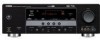
... "SET MENU". Designates the default audio input jack select setting for the input sources connected to the DIGITAL INPUT jacks when you turn on the power of this feature to check audio signal information (see page 33). The top "SET MENU" display appears in the OSD. ;MANUAL SETUP . 1 SOUND MENU 2 INPUT...
... "SET MENU". Designates the default audio input jack select setting for the input sources connected to the DIGITAL INPUT jacks when you turn on the power of this feature to check audio signal information (see page 33). The top "SET MENU" display appears in the OSD. ;MANUAL SETUP . 1 SOUND MENU 2 INPUT...

Owner's Manual
Page 59
..., the original volume range is 16 dB to reassign the respective jacks and effectively connect more than once. is set the volume level when the power of this unit is useful to your needs. For example, if "INI VOL." p SET MENU 2 INPUT MENU Use this unit do not correspond to... sound by using DINPUT l / h (or the input selector buttons (A)). English 55 En ADVANCED OPERATION p Maximum volume MAX VOL. This feature is turned on the power of this menu to reassign the input jacks, select the decoder mode or rename the input source. ;MANUAL SETUP 2 INPUT MENU . Use this feature to...
..., the original volume range is 16 dB to reassign the respective jacks and effectively connect more than once. is set the volume level when the power of this unit is useful to your needs. For example, if "INI VOL." p SET MENU 2 INPUT MENU Use this unit do not correspond to... sound by using DINPUT l / h (or the input selector buttons (A)). English 55 En ADVANCED OPERATION p Maximum volume MAX VOL. This feature is turned on the power of this menu to reassign the input jacks, select the decoder mode or rename the input source. ;MANUAL SETUP 2 INPUT MENU . Use this feature to...
Owner's Manual
Page 60
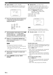
...CH IN CD CD-R DVD CBL DTV TUNER XM DOCK V-AUX DVR 2 Set the operation mode selector (K) to AMP and then press Dl / h on the power of this unit. DTS decoder prioritize setting Choices: AUTO, DTS • Select "AUTO" if you play back a DTS-CD. 56 En Choices: CD, MD... / h to move to the next space. [p]/[[]:Adjust [RETURN]:Exit Note You can only adjust the value for DOCK when your iPod is stationed in the Yamaha Universal Dock connected to this unit. ■ Decoder mode D)DECODER MODE 2 INPUT MENU D)DECODER MODE . >AUTO LAST CD ;;;;AUTO DVD ;;;;AUTO DTV/CBL ;;;;AUTO [ ]/[ ...
...CH IN CD CD-R DVD CBL DTV TUNER XM DOCK V-AUX DVR 2 Set the operation mode selector (K) to AMP and then press Dl / h on the power of this unit. DTS decoder prioritize setting Choices: AUTO, DTS • Select "AUTO" if you play back a DTS-CD. 56 En Choices: CD, MD... / h to move to the next space. [p]/[[]:Adjust [RETURN]:Exit Note You can only adjust the value for DOCK when your iPod is stationed in the Yamaha Universal Dock connected to this unit. ■ Decoder mode D)DECODER MODE 2 INPUT MENU D)DECODER MODE . >AUTO LAST CD ;;;;AUTO DVD ;;;;AUTO DTV/CBL ;;;;AUTO [ ]/[ ...

Owner's Manual
Page 62
... off the "MEMORY GUARD" feature. • Select "ON" to automatically select the last input mode used for the input sources when you turn on the power of this unit. and Canada models only) 3 OPTION MENU E)XM RADIO SET XM ANTENNA;;;95% [ENTER]:Return [p]/[[]:Select • Select "AUTO" if you want this...
... off the "MEMORY GUARD" feature. • Select "ON" to automatically select the last input mode used for the input sources when you turn on the power of this unit. and Canada models only) 3 OPTION MENU E)XM RADIO SET XM ANTENNA;;;95% [ENTER]:Return [p]/[[]:Select • Select "AUTO" if you want this...

Owner's Manual
Page 63
.... 2 Press the desired buttons in step 2 until the VTRANSMIT indicator flashes twice again. In this unit and the input source component by Yamaha and other components, you must set up the appropriate remote control code for each input source (see page 62). ■ Setting input source... TV or other manufacturers. ADVANCED OPERATION English 59 En Note If the setting of the selected SCENE template. * CODE SET TRANSMIT POWER TV POWER AV STANDBY POWER CD DVD DOCK V-AUX MD CD-R CBL DTV MULTI CH IN AUDIO SEL TUNER XM DVR TV VOL TV CH AMP VOLUME SOURCE...
.... 2 Press the desired buttons in step 2 until the VTRANSMIT indicator flashes twice again. In this unit and the input source component by Yamaha and other components, you must set up the appropriate remote control code for each input source (see page 62). ■ Setting input source... TV or other manufacturers. ADVANCED OPERATION English 59 En Note If the setting of the selected SCENE template. * CODE SET TRANSMIT POWER TV POWER AV STANDBY POWER CD DVD DOCK V-AUX MD CD-R CBL DTV MULTI CH IN AUDIO SEL TUNER XM DVR TV VOL TV CH AMP VOLUME SOURCE...

Owner's Manual
Page 64
...Set the operation mode selector to TV to control your TV only when the operation mode selector is set to TV. CODE SET TRANSMIT POWER TV POWER AV STANDBY POWER CD DVD DOCK V-AUX MD CD-R CBL DTV MULTI CH IN AUDIO SEL TUNER XM DVR TV VOL TV CH AMP VOLUME SOURCE TV... ENT LEVEL TITLE BAND RETURN XM MEMORY PRESET/CH SET MENU MENU SRCH MODE ENTER A-E/CAT. TV CH +/- DISPLAY REC SCENE 1 2 3 4 *1 *2 *1 *1 CODE SET TRANSMIT POWER TV POWER AV STANDBY POWER CD DVD DOCK V-AUX MD CD-R CBL DTV MULTI CH IN AUDIO SEL TUNER XM DVR TV VOL TV CH AMP VOLUME SOURCE TV...
...Set the operation mode selector to TV to control your TV only when the operation mode selector is set to TV. CODE SET TRANSMIT POWER TV POWER AV STANDBY POWER CD DVD DOCK V-AUX MD CD-R CBL DTV MULTI CH IN AUDIO SEL TUNER XM DVR TV VOL TV CH AMP VOLUME SOURCE TV... ENT LEVEL TITLE BAND RETURN XM MEMORY PRESET/CH SET MENU MENU SRCH MODE ENTER A-E/CAT. TV CH +/- DISPLAY REC SCENE 1 2 3 4 *1 *2 *1 *1 CODE SET TRANSMIT POWER TV POWER AV STANDBY POWER CD DVD DOCK V-AUX MD CD-R CBL DTV MULTI CH IN AUDIO SEL TUNER XM DVR TV VOL TV CH AMP VOLUME SOURCE TV...

Owner's Manual
Page 65
... 3 4 7 8 9 Remote control DVD player/ recorder VCR Digital TV/ Cable TV LD player CD player MD/CD recorder Tuner iPod 1 AV POWER Power *1 Power *1 Power *2 Power *1 Power *1 Power *1 2 1-9, 0, +10 3 TITLE Numeric buttons Title Numeric buttons Numeric buttons Numeric buttons Numeric buttons Numeric buttons Preset stations (1-8) Band 4 PRESET...other components Set the operation mode selector (K) to SOURCE to 10 different components. 1 CODE SET TRANSMIT POWER TV POWER AV STANDBY POWER CD DVD DOCK V-AUX MD CD-R CBL DTV MULTI CH IN AUDIO SEL TUNER XM DVR TV ...
... 3 4 7 8 9 Remote control DVD player/ recorder VCR Digital TV/ Cable TV LD player CD player MD/CD recorder Tuner iPod 1 AV POWER Power *1 Power *1 Power *2 Power *1 Power *1 Power *1 2 1-9, 0, +10 3 TITLE Numeric buttons Title Numeric buttons Numeric buttons Numeric buttons Numeric buttons Numeric buttons Preset stations (1-8) Band 4 PRESET...other components Set the operation mode selector (K) to SOURCE to 10 different components. 1 CODE SET TRANSMIT POWER TV POWER AV STANDBY POWER CD DVD DOCK V-AUX MD CD-R CBL DTV MULTI CH IN AUDIO SEL TUNER XM DVR TV ...

Owner's Manual
Page 66
...enter the five-digit remote control code for the selected input area is preset as listed above. In this case, try setting another Yamaha remote control code. 1 Press one code, try each of this happens, repeat the setup procedure. • If you enter the... y Refer to be able to set up. If this manual. TUNER TUNER YAMAHA 82005 XM TUNER YAMAHA 82006 V-AUX DVR OTHER AUDIO ACCESSORIES (iPod) DVR YAMAHA YAMAHA 82000 52001 - - - - - - CODE SET TRANSMIT POWER TV POWER AV STANDBY POWER DVD Lights up . For a complete list of available remote control codes, refer...
...enter the five-digit remote control code for the selected input area is preset as listed above. In this case, try setting another Yamaha remote control code. 1 Press one code, try each of this happens, repeat the setup procedure. • If you enter the... y Refer to be able to set up. If this manual. TUNER TUNER YAMAHA 82005 XM TUNER YAMAHA 82006 V-AUX DVR OTHER AUDIO ACCESSORIES (iPod) DVR YAMAHA YAMAHA 82000 52001 - - - - - - CODE SET TRANSMIT POWER TV POWER AV STANDBY POWER DVD Lights up . For a complete list of available remote control codes, refer...


